Introduction
Several methods are available to enhance the precision of miniscrew placement. The use of surgical guides based on cone-beam computed tomography is indicated especially in patients with risky or difficult anatomic situations. The purpose of this study was to evaluate the accuracy of miniscrew placement by using surgical guides developed with computer-aided design and manufacturing techniques.
Methods
Miniscrews were placed in cadaver maxillae using stereolithographic computer-aided design and manufacturing techniques with assistance from surgical guides (surgical guide group, n = 25) or periapical x-rays (control group, n = 20). Insertion sites were selected using a 3-dimensional surgical planning program by fusing maxillary digital model images and cone-beam computed tomography images. Deviations between actual and planned placements were measured as 3-dimensional angular deviations and distance (coronal and apical) deviations.
Results
In the surgical guide group, the angular deviation was a median of 3.14° (range, 1.02°-10.9°), and the mesiodistal deviations in the coronal and apical areas were medians of 0.29 mm (range, 0.03-0.73 mm) and 0.21 mm (range, 0.03-0.97 mm), respectively. The deviations differed significantly between operators in the control group, but not in the surgical guide group. In the surgical guide group, there was no root damage from miniscrew placement, and 84% of the miniscrews were placed without contacting adjacent anatomic structures. In the control group, 50% of the miniscrews were placed between the roots ( P <0.05).
Conclusions
Surgical guide accuracy was improved when digital model imaging was used. Miniscrews were placed more accurately when using surgical guides than when using a direct method.
Orthodontic miniscrews provide skeletal anchorage with the advantages of ease of implantation and no need for patient cooperation. Therefore, the use of skeletal anchorage has increased because it can overcome the limitations of conventional orthodontic treatment methods, as reported in several studies. As the use of miniscrews has increased, various studies regarding methods for providing improved stability of miniscrews after or during placement have been published.
The most common problem encountered during miniscrew insertion is the lack of precise knowledge of the anatomy of the insertion area. Several methods have been described in the literature to enhance the precision of the insertion of the screws. Surgical guides based on cone-beam computed tomography (CBCT) are indicated especially in patients with risky or difficult anatomic situations.
The proximity of a miniscrew to tooth structures has been reported to be a major risk factor for failure. Kuroda et al classified the success rates of miniscrews according to root proximity. In the root-contact group, the success rate of implantations in the mandible was low (35.3%). Although some authors have argued that root surfaces in contact with miniscrews repair swiftly and heal almost completely after removal of the miniscrew or the orthodontic force, conflicting previous reports have associated root contact with lower miniscrew success rates.
Root contact is most often due to limited interradicular space at the implantation site. Considering anatomic interradicular distances and thickness of cortical bone, authors have recommended using orthodontic miniscrews that are 1.2 to 1.6 mm in diameter and 6 to 7 mm in length. In addition to anatomic factors, root contact that occurs as a result of the operator’s skill level contributes to decreased stability of miniscrews.
To improve the stability and success rate of miniscrews, placement methods that minimize root contact are being developed. The conventional wire-guide method, in which a simple wire is used in conjunction with periapical radiographs, is often used. Another method, in which the miniscrews are placed using a resin splint-type guide made from a plaster model, has also been introduced.
Recent improvements in 3-dimensional (3D) imaging techniques have provided a means to overcome the limitations of 2-dimensional (2D) images. The positional relationships of roots can only be seen on radiographic images, and it is difficult to predict the accurate location and distance with only 2D radiographs. However, the application of computed tomography techniques to 3D dental images has made it possible to accurately evaluate the spatial and positional relationships between teeth. Methods for the construction of guides for miniscrew placement that use 3D imaging techniques, such as CBCT, 3D software, and stereolithography apparatuses have been reported. However, studies regarding clinically applicable miniscrew surgical guides are still insufficient because of the difficulty in minimizing their intraoral size and the limits in accurately fabricating the guides from 3D images.
Therefore, the purpose of this study was to evaluate the accuracy of miniscrew placement when using surgical guides created with computer-aided design and computer-aided manufacturing techniques, and after planning the appropriate insertion sites with 3D images created by fusion of CBCT and digital model images. The stability of miniscrew placement independent of the operator’s skill level when the surgical guide was used was also investigated. With the use of CBCT and digital model images, we believe that the resulting miniscrew surgical guides are simpler in design and easier to use clinically.
Material and methods
The miniscrews (BMK; Biomaterials Korea, Seoul, Korea) used in this study were a cylinder-type, 1.5 mm in diameter and 7.0 mm in length. A total of 45 miniscrews (surgical guide group, n = 25; control group, n = 20) were placed. Miniscrews were placed in 12 cadaver maxillae with sound bone quality and soft tissues ( Table I ).
| Surgical guide group | Control group | |
|---|---|---|
| Ilat-C | 2 | 3 |
| C-Pm1 | 5 | 3 |
| Pm1-Pm2 | 6 | 6 |
| Pm2-M1 | 6 | 4 |
| M1-M2 | 6 | 4 |
| Total | 25 | 20 |
Impressions of the cadaver maxillae were taken to make plaster models. Regular and light Aquasil Ultra (Dentsply International, York, Pa) and rubber impression materials were used to take impressions. Plaster models were made by pouring New Plastone White (GC, Tokyo, Japan) into the impressions. The plaster models were reconstructed into digital models using a scanner (model KOD-300; Orapix, Seoul, Korea) for fusion with the CBCT images. CBCT-Rayscan Symphony (Ray, Kyungi Province, Korea) images were obtained for each cadaver maxilla. Default values used for obtaining both preoperative and postoperative images were 80 kV, 10 mA, and 0.5-mm focal spot size ( Fig 1 , A and B ).
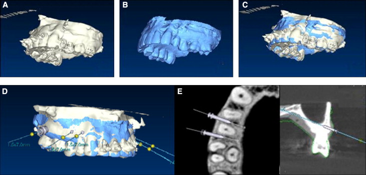
The digital model images were fused with CBCT images using 3D software (OnDemand 3D; Cybermed, Seoul, Korea; Fig 1 , C ). A 3D computed tomography image was constructed using the axial view in the CBCT data. Three points were designated on this image and on the digital model image first, and then the surface of a desired site was chosen for fusion of the images. After the interradicular distances were measured on the fused images, miniscrew placement was planned using imaginary miniscrews. When planning miniscrew placement, the relationship between the roots and the insertion depth was evaluated in the axial view, although the coronal view and the digital models were also considered. Positive angulation was given to the occlusal plane 4 to 6 mm from the cervical area, according to the ideal insertion location reported in the literature. Imaginary placement was conducted while allowing for deviation of the insertion angle according to the surface of the insertion site and the slope of the alveolar bone ( Fig 1 , D ).
The placement plan file was uploaded onto the dental laboratory’s Web site for surgical guide fabrication. The surgical guides had a tooth-borne shape, and each guide included 4 teeth to ensure stable retention. The surgical guides were made using the computer-aided design and manufacturing method and included metal sleeves so that the miniscrews could be placed at the planned locations ( Fig 2 , A ).
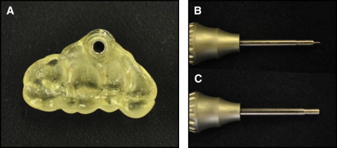
In the control group, the position of the miniscrews was determined using 2D periapical radiographs that were reconstructed from the CBCT images. Miniscrews in the control group were placed by measuring placement height with a dental probe via a direct manual method. In the surgical guide group, after placing the surgical guide, predrilling was performed using a 1.2-mm-wide predrilling driver. The miniscrews in this group were placed with a miniscrew driver that was guided by the surgical guide ( Table I ; Fig 2 , B and C ).
The miniscrews were placed by 2 orthodontists (J.-Y.C. and H.-S.Y.). CBCT scans of both groups were obtained after placement.
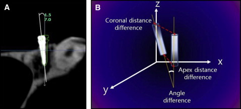
We used the 3D analysis program to determine the deviations in angle and location between the planned and actual miniscrew placements in the cadaver maxillae. CBCT images taken before and after miniscrew placement were superimposed on the 3D axis. The file containing the planned miniscrew placement was opened over this superimposed image to compare the locations of the planned and actual miniscrew placements. The angular deviation was measured using the long axis of the miniscrews, and the distance deviation was measured at the coronal and apical areas of the miniscrews.
In the computed tomography coordinate system, the dx value indicates the depth of the miniscrew, the dy value indicates the mesiodistal location, and the dz value indicates the vertical position. These values are reported as a sum value that was converted to a linear distance in 3D space ( Fig 3 ).
After placement, the miniscrews were categorized into one of 3 classifications: middle position, with the miniscrews placed between the roots of the teeth; root contact, with the miniscrews touching the roots of the tooth (invading the periodontal ligament space); and root damage, with the miniscrews placed so that they damaged the roots, as indicated by the CBCT axial view. The frequencies of these classifications were compared between the groups.
Statistical analysis
Each variable was measured twice, with 2 weeks between measurements, and there was no significant difference between the measurements ( P >0.05). The height and angle of miniscrew insertion and the minimum interradicular distance are reported as means and standard deviations. Deviations between the planned and actual miniscrews are reported as medians (minimum and maximum) because the deviations for neither the surgical guide group nor the control group were normally distributed. To find the differences in angle and location of miniscrew placements as well as differences between operators in the control and surgical guide groups, Wilcoxon 2-sample tests were performed using nonparametric Wilcoxon scores (rank sums). Group differences in classification frequency of root proximity were determined to be significant if the Fisher exact test yielded P <0.05.
Results
The mean value of the minimum interradicular distance in the maxilla, as seen in the CBCT axial view, was 2.80 mm (SD, ±0.67 mm) ( Table II ).
| Miniscrew implantation area | Total | ||||||||||
|---|---|---|---|---|---|---|---|---|---|---|---|
| Ilat-C | C-Pm1 | Pm1-Pm2 | Pm2-M1 | M1-M2 | |||||||
| Mean | SD | Mean | SD | Mean | SD | Mean | SD | Mean | SD | Mean | SD |
| 2.43 | 0.20 | 3.00 | 0.87 | 2.89 | 0.51 | 2.96 | 0.89 | 2.62 | 0.48 | 2.80 | 0.67 |
Statistically significant differences were detected in the long-axis angular deviations between the surgical guide group, with a median of 3.14° (range, 1.02°-10.9°), and the control group, with a median of 9.57° (range, 3.15°-35.60°) ( P <0.001). The 3D linear distance deviations of the miniscrews in the surgical guide group were medians of 0.73 mm (range, 0.26-1.12 mm) at the coronal position and 0.73 mm (range, 0.24-2.07 mm) at the apex. For the control group, these values were medians of 1.56 mm (range, 0.59-2.95 mm) and 1.28 mm (range, 0.26-3.81 mm), respectively. Statistically significant differences were observed between the surgical guide and control groups for both values ( P <0.01).
The dx , dy , and dz deviation values in the surgical guide group at the apex were medians of 0.38 mm (range, 0.01-1.11 mm), 0.21 mm (range, 0.03-0.97 mm), and 0.39 mm (range, 0.04-1.42 mm), respectively. We found no statistically significant differences in the dx and dy values between the planned and actual placements ( Table III ).
| Surgical guide group | Control group | Significance | |||||
|---|---|---|---|---|---|---|---|
| Median | Minimum | Maximum | Median | Minimum | Maximum | ||
| Angle (°) | 3.14 | 1.02 | 10.9 | 9.57 | 3.15 | 35.60 | ∗ |
| Coronal (mm) | |||||||
| Sum | 0.73 | 0.26 | 1.12 | 1.56 | 0.59 | 2.95 | ∗ |
| dx | 0.40 | 0.03 | 1.05 | 0.30 | 0.08 | 1.55 | |
| dy | 0.29 | 0.03 | 0.73 | 0.81 | 0.12 | 2.36 | † |
| dz | 0.35 | 0.01 | 0.76 | 0.69 | 0.11 | 2.57 | † |
| Apex (mm) | |||||||
| Sum | 0.73 | 0.24 | 2.07 | 1.28 | 0.26 | 3.81 | † |
| dx | 0.38 | 0.01 | 1.11 | 0.33 | 0.04 | 1.39 | |
| dy | 0.21 | 0.03 | 0.97 | 0.36 | 0.02 | 3.02 | |
| dz | 0.39 | 0.04 | 1.42 | 0.91 | 0.12 | 3.74 | ‡ |
Stay updated, free dental videos. Join our Telegram channel
VIDEdental - Online dental courses


