Fig. 9.1
Fluorapatite crystal structure [16]. Note that the only difference between the fluorapatite and HA cells is that the HA unit cell is slightly larger. Black = calcium, Yellow = phosphorous, Pink = oxygen
HA, like all apatites, has a hexagonal system with space group P63/m [11, 17]. The acceptance of a hexagonal P63 structure provides a poor least squares fit to XRD data. Therefore, two monoclinic models have been suggested: P21/b [18] and P21 [19]. Their chemical composition and Ca/P ratios are summarised in Table 9.1.
|
Symbol
|
Chemical formula
|
Chemical definition
|
Ca/P
|
|---|---|---|---|
|
MCP
|
Ca(H2PO4)2
|
Monocalcium phosphate hydrate
|
0.5
|
|
DCPA
|
CaHPO4
|
Dicalcium phosphate anhydrous
|
1.00
|
|
DCPD
|
CaHPO.2H2O
|
Dicalcium phosphate dihydrate
|
1.00
|
|
OCP
|
Ca8H2(PO4)6.5H2O
|
Octacalcium phosphate
|
1.33
|
|
α-TCP
|
α-Ca3(PO4)2
|
α-Tricalcium phosphate
|
1.5
|
|
β-TCP
|
β-Ca3(PO4)2
|
β-Tricalcium phosphate
|
1.50
|
|
TTCP
|
Ca4(PO4)2O
|
Tetracalcium phosphate
|
2.00
|
|
OHA
|
Ca10(PO4)6(OH)2 − 2xOx
|
Oxyhydroxyapatite
|
1.67
|
|
OA
|
Ca10(PO4)6O
|
Oxyapatite
|
1.67
|
|
HA
|
Ca10(PO4)6(OH)2
|
Hydroxyapatite
|
1.67
|
Figure 9.2a shows the phase diagram of HA with no water present and (b) at a partial water pressure of 500 mmHg. Figure 9.2a indicates that HA can decompose into other calcium phosphates such as tetracalcium phosphate (TTCP), tricalcium phosphate (TCP), monetite (C2P), and mixtures of calcium oxide (CaO) and C4P. Figure 9.2b shows that HA is stable up to 1,550 °C. The two renditions of the phase diagram indicate that the phase equilibrium of HA is influenced greatly by the partial pressure of water in the surrounding atmosphere. Fang et al. [24] reported the effect of stoichiometry on the thermal stability of HA from experiments where HA powder samples with Ca/P ratios remained within 1.52–1.68 when heated to 1,100 °C.
Fig. 9.2
(a) Phase diagram of the system CaO–P2O5 at high temperature. No water present. (b) Phase diagram of the system of Cao-P2O5 at high temperature and at a partial water pressure of 500 mmHg. (Note: There are many references to the hydroxyapatite phase diagram. The following references are examples where information can be accessed (White et al. [22]; Gross et al. [23]))
These potential changes in phase structure are of direct relevance since the DC plasma operates under high pressures at atmospheric conditions that comprise water vapour.
9.2.1.2 Comparison of Hydroxyapatite and Bone
HA, due to its apatite structure, contains structural sites that allow substitution of other ions. For example, if there is a deficiency in either calcium or carbonate species, then sodium (Na+), magnesium (Mg2+), acid phosphate (HPO4), potassium (K+), carbonate (CO3 2−), fluoride (F−), and chloride (Cl−) ions may be substituted as minor elements. The trace elements of strontium (Sr2+), barium (Ba2+), and lead (Pb2+) may also be observed. Synthetic HA and the main constituents of the bone are compared in Table 9.2.
Table 9.2
Comparison of bone and hydroxyapatite ceramics (Nicholson [25])
|
Constituents (wt.%)
|
Bone
|
HAa
|
|---|---|---|
|
Ca
|
24.5
|
39.6
|
|
P
|
11.5
|
18.5
|
|
Ca/P ratio
|
1.65
|
1.67
|
|
Na
|
0.7
|
Trace
|
|
K
|
0.03
|
Trace
|
|
Mg
|
0.55
|
Trace
|
|
CO3 2−
|
5.8
|
–
|
There are different methods available to deposit calcium phosphate, and their mechanical properties vary accordingly. Likewise, HA powder differs in grain size and in composition because of different preparation methods for the HA scaffold materials. Small grain size provides greater fracture toughness. Table 9.3 shows a comparison of mechanical properties of cortical bone, cancellous bone, and HA scaffolds where large variations can be observed.
9.2.1.3 Dissolution Behaviour
Hydroxyapatite is very stable in physiological media. However, the dissolution rates of other phases formed due to the high temperature of the plasma spray process are more pronounced. The phases that appear in the HA coating are tricalcium phosphate (Ca3(PO4)2, TCP, i.e. α-TCP and/or β-TCP), tetracalcium phosphate (Ca4P2O9, i.e. TTCP), calcium oxide (CaO), oxyhydroxyapatite (OHA), and oxyapatite (OA). Hydroxyapatite may also exist as an amorphous phase, ACP. The dissolution order is as follows [11, 28]:
![$$ \mathrm{CaO}/>\mathrm{TCP}>\mathrm{ACP}>\mathrm{TTCP}>\mathrm{OHA}/\mathrm{OA}>\mathrm{HA} $$
” src=”/wp-content/uploads/1008/A312282_1_En_9_Chapter_Equa.gif”></div>
</div>
</div>
</div>
<div class=Para>Among these phases, CaO is known to be biocompatible when incorporated into a silicate glass. However, it dissolves significantly faster than the other phases in the CaO–P<sub>2</sub>O<sub>5</sub> phase diagram, and therefore, CaO is considered as a detrimental phase for orthopaedic applications. The dissolution of a HA coating increases with an increase in porosity and surface area and a decrease in particle size and crystallinity. Coatings sprayed at lower power (27.5 kW) demonstrated crystalline HA, whereas coatings sprayed at higher power (42 kW) exhibited amorphous phases [<cite><a href=]() 29].
29].


The dissolution of unstable phases in the coating leads to an undesirable reduction of the mechanical strength in a coating. It should be kept in mind though that these dissolved phases have been shown to enhance bone tissue growth [30, 31] so that there is a compromise between dissolution rate and growth rate. Ducheyne et al. [30] compared the performance of three calcium phosphate coatings (polylactic acid/calcium-deficient HA, calcium-deficient HA, and oxyhydroxyapatite/α-TCP/β-TCP) with an uncoated implant in vivo. The calcium phosphate-coated implants were observed to permit a greater degree of bone growth than the uncoated implant.
9.2.1.4 Thermal Behaviour
Plasma-sprayed HA coatings are formed with a significantly different crystal structure, phase composition, and morphology than the original starting powder. This outcome arises because the plasma spray process involves melting of particles that causes thermal decomposition and changes the phase balance of the individual particles [32]. The changes occurring within the plasma flame need to be understood to ensure that the coating produced has the required composition.
The heating of HA leads to three processes. They are (1) evaporation of water, (2) dehydroxylation, and (3) decomposition. Hydroxyapatite has the property to absorb water that may be present on the surface of the powder and trapped within pores [33]. The absorbed water begins to evaporate when heated and is followed by water within the lattice structure [34]. The dehydroxylation reaction reported by several authors [34, 35] is as follows, where V represents a vacancy and x < 1:
![$$ \begin{aligned}[b]&{\mathrm{Ca}}_{10}{\left({\mathrm{PO}}_4\right)}_6{\left(\mathrm{OH}\right)}_2\hfill \to {\mathrm{Ca}}_{10}{\left({\mathrm{PO}}_4\right)}_6{\left(\mathrm{OH}\right)}_{2-2x}\mathrm{O}_x \mathrm{V}_x+x{\mathrm{H}}_2\mathrm{O}\hfill \\ &\mathrm{Hydroxyapatite} \to \mathrm{Oxyhydroxyapatite} \end{aligned} $$](/wp-content/uploads/1008/A312282_1_En_9_Chapter_Equ1.gif)
![$$ \begin{aligned}[b]&{\mathrm{Ca}}_{10}{\left({\mathrm{PO}}_4\right)}_6{\left(\mathrm{OH}\right)}_{2-2x}{\mathrm{O}}_x\mathrm{V}_x\hfill \to \hfill {\mathrm{Ca}}_{10}{\left({\mathrm{PO}}_4\right)}_6{\mathrm{O}}_x\mathrm{V}_x+\left(1-x\right){\mathrm{H}}_2\mathrm{O}\hfill \\ &\mathrm{Oxyhydroxyapatite}\hfill \to \hfill \mathrm{Oxyapatite}\hfill \end{aligned} $$](/wp-content/uploads/1008/A312282_1_En_9_Chapter_Equ2.gif)
(9.1)
(9.2)
The first step involves the formation of a hydroxyl ion-deficient product, known as oxyhydroxyapatite (OHA). OHA consists of a bivalent oxygen ion and a vacancy substitute for two monovalent OH− ions of HA [34]. In the second step, dehydroxylation leads to the formation of oxyapatite. In the presence of water, oxyhydroxyapatite and oxyapatite can transform back to hydroxyapatite [28].
Hydroxyapatite decomposes into other phases at high temperature. HA retains its crystal structure up to a critical point, beyond which complete and irreversible decomposition occurs. During decomposition, HA converts into other calcium phosphate phases such as β-tricalcium phosphate (β-TCP) and tetracalcium phosphate (TTCP). Firstly, oxyapatite transforms into tricalcium phosphate and tetracalcium phosphate. In the next step, tricalcium phosphate and tetracalcium phosphate convert into calcium oxide [34, 36, 37]. The chemical equilibria can be described by means of the three following equations:
![$$ \begin{aligned}[b]&{\mathrm{Ca}}_{10}{\left({\mathrm{PO}}_4\right)}_6{\mathrm{O}}_x\mathrm{V}_x\hfill \to 2{\mathrm{Ca}}_3{\left({\mathrm{PO}}_4\right)}_2\left(\upbeta \right) + {\mathrm{Ca}}_4{\left({\mathrm{PO}}_4\right)}_2\mathrm{O}\hfill \\ &\mathrm{Oxyapatite} \to \mathrm{Tricalcium}\ \mathrm{phosphate} + \mathrm{Tetracalcium}\ \mathrm{phosphate}\hfill \end{aligned} $$](/wp-content/uploads/1008/A312282_1_En_9_Chapter_Equ3.gif)
![$$ \begin{aligned}[b]&{\mathrm{Ca}}_3{\left({\mathrm{P}\mathrm{O}}_4\right)}_2 \to 3\mathrm{CaO}+ {\mathrm{P}}_2{\mathrm{O}}_5 \\ &\mathrm{Tricalcium}\ \mathrm{phosphate}\to \mathrm{Calcium}\ \mathrm{oxide}+ \mathrm{Phosphorus}\ \mathrm{pentoxide}\end{aligned} $$](/wp-content/uploads/1008/A312282_1_En_9_Chapter_Equ4.gif)
![$$ \begin{aligned}[b]&{\mathrm{Ca}}_4{\left({\mathrm{P}\mathrm{O}}_4\right)}_2\mathrm{O} \to 4\mathrm{CaO} + {\mathrm{P}}_2{\mathrm{O}}_5 \\ &\mathrm{Tetracalcium}\ \mathrm{phosphate} \to \mathrm{Calcium}\ \mathrm{oxide} + \mathrm{Phosphorus}\ \mathrm{pentoxide} \end{aligned} $$](/wp-content/uploads/1008/A312282_1_En_9_Chapter_Equ5.gif)
(9.3)
(9.4)
(9.5)
It is difficult to predict the exact temperatures for these reactions because they occur over a wide temperature range that depends on factors related to the environment and the HA composition. Table 9.4 lists the reactions that occur as HA is heated from room temperature to 1,730 °C, keeping in mind that these have not been validated under the extreme environments of a DC plasma process.
Table 9.4
Thermal effects of hydroxyapatite (Levingstone [38])
|
Temperature (°C)
|
Reaction(s)
|
|---|---|
|
25–200
|
Evaporation of absorbed water
|
|
200–600
|
Evaporation of lattice water
|
|
600–800
|
Decarbonation
|
|
800–900
|
Dehydroxylation of HA forming partially or completely dehydroxylated oxyhydroxyapatite
|
|
1,050–1,400
|
HA decomposes to form β-TCP and TTCP
|
|
<1,120
|
β-TCP is stable
|
|
1,120–1,470
|
β-TCP is converted to α-TCP
|
|
1,550
|
Melting temperature of HA
|
|
1,630
|
Melting temperature of TTCP, leaving behind CaO
|
|
1,730
|
Melting of TCP
|
9.2.2 Hydroxyapatite Powder
HA feedstock is the foundation for each thermal spray process. The ASTM standard F 1609 [39], which is comparable with other standards from FDA or ISO, provides limitations for feedstock concerning crystallinity, particle form, and in vivo and in vitro behaviour. Therefore, several common parameters for the feedstock have become accepted. Usually, a fully crystalline pure HA powder is the basis, which is generally manufactured by using phosphate-containing and calcium ion-containing ingredients. After mixing both components, calcination leads to the HA feedstock [40].
The ASTM Standard Specification (ASTM designation: F1185-88 [41]) states that surgical implants require a minimum of 95 % of HA content, established by a quantitative X-ray diffraction (XRD) analysis, while the concentration of trace elements should be limited, e.g. arsenic 3 ppm, cadmium 5 ppm, mercury 5 ppm, and lead 30 ppm. The HA phase is required by the International Standards Institute (ISO 13778-1: 2000, Implants for surgery, Hydroxyapatite – Part 1: Ceramic hydroxyapatite) [42] to exhibit a crystallinity of at least 45 %. The maximum allowable total limit of all heavy metals is 50 ppm. The Ca/P ratio for HA used for surgical implants must be between 1.65 and 1.82 [41].
The quality of coatings depends on the shape of HA powders for plasma spray deposition. The particles are melted or partly melted in the plasma flame; thus, the morphology of the powder particles relates directly to the heating rate. Irregularly shaped particles exhibit a higher degree of particle heating within the plasma flame due to their greater surface area to volume ratio than spherical particles [43]. Spherical particles have better flow properties than angular particles and can be more reliably transported to the plasma flame.
Powder with a narrow range of particle sizes will result in a more consistent coating. The particles must also be capable of withstanding the spray environment. For example, Cheang and Khor [44] observed that weakly agglomerated HA powders fragment within the plasma stream giving a new distribution of smaller particles that influences the coating microstructure.
9.3 Human Bone
Since the main intention of HA implant coatings is to support the growth of human bone tissue on the implant surface, it is necessary to understand the structure of this tissue and its modelling and remodelling behaviour. In this way, the intention is to design an artificial microstructure that mimics the performance criteria of natural bone.
In general, there are two types of bone tissue, the high and the low porous ones, called the compact and the trabecular bone [45]. With 75–95 % porosity [45], the trabecular bone (also called cancellous or spongy bone) is mostly found in the epiphysis, the ends of long bones [46]. There the matrix is formed of 200 μm thick [45] trabeculae. The trabeculae matrix formation directions follow the principal stress axes [47] within the bone that allows the transfer of high loads along these axes. Overall, the trabeculae of the cancellous bone form 80 % of the bone surface [48].
The high-density bone is found in the middle parts of long bones, the diaphysis, and in the outer parts of bones, where it forms the bone shell that is termed cortical bone. With 80–85 % of the skeletal bone mass, it provides protection and strength for the whole bone [48]. This compact matrix shows a porosity from 5 to 10 % [45, 49]. Within the pores of the matrix, there are tissue types that display different morphologies and character [47], the detail of which is considered out of scope for this current chapter.
Primary bone is located on the bone surface. A new bone structure will be arranged parallel to this shell structure and is termed as “lamellae”. The bone matrix itself is continuously changing. Therefore, the primary structure will be replaced by the secondary bone. It is interesting to note that the substructure of the bone has a morphology of 200 μm in diameter and consists of approximately 16 layers [45] that are surrounded by a cement line. This dimensional feature is similar to the dimensions of a single HA splat that is formed via thermal spray processing.
9.3.1 The Composite Structure of Bone
Bone is composed of collagen, HA mineral, water, and particles of noncollagenous proteins and proteoglycans [45, 50]. In general, 30 % of the bone matrix is organic substance (collagen), and 70 % is inorganic (with water being ∼25 % and HA ∼45 %) [45, 51]. Collagen is a protein that exists in many organs and tissues in the human body. Due to its solubility and a constant blood flow in the bone matrix, other components such as fluoride and carbonate can add impurities to the HA bone substructure [45].
As seen in the investigation of Robinson and Elliott (1957) [52] on dog bones, which are comparable to human bones, most of the organic matrix is composed of collagen. Furthermore, it is interesting that over 50 % of the HA apatite minerals are found within the collagen fibres, which may be proof that collagen structures are fundamental for the mineralisation of the bone.
Modelling and remodelling – forming and resorbing of bone material – are permanent processes in bone tissue. Four different bone cells are responsible for this behaviour: osteoclasts, osteoblasts, osteocytes, and bone lining cells [49].
Osteoclasts are multinuclear, amoebic cells [45, 53], covering nearly one per cent of the bone surface [49]. These cells are in charge for the resorption of the bone matrix. The cells produce acids to demineralise the bone surface and, afterwards, dissolve the bone collagen with enzymes [45]. Using this process, osteoclasts can resorb bone to a depth of tens of micrometres per day [45].
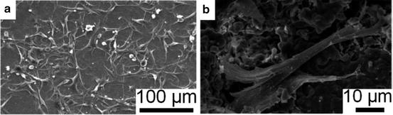
Osteoblasts (Fig. 9.3) exist on the surface of bone-forming areas [53]. They are mononuclear, cuboidal cells [45] with an approximate diameter of 20 μm [53]. The main task of these cells is to produce collagen and other components of the organic bone matrix [45, 53]. This process takes place to an amount of ∼1 μm per day, which is termed the bone apposition rate [45]. Studies have shown that osteoblasts are, as well, connected with the bone resorption process; that is, it has been suggested that osteoblasts control the activities of osteoclasts [53].
Some osteoblasts enclose themselves into the matrix during the bone modelling process. Approximately 10 % of them will transform into osteocytes, which are responsible for the long-term functionality of the bone matrix [49]. These cells are connected with each other and the bone surface via a wide-ranging net of channels, the canaliculi [45, 53]. These tunnels enable communication and the transport of minerals into the bone matrix [45], which enables the matrix internal mineralisation process.
9.3.2 Bone Modelling and Remodelling
There are two bone formation processes, i.e. the endochondral and the intramembranous modelling processes [56]. The specialised cells need an unmineralised tissue to mineralise bone matrix as a foundation. But when a bone grows, this interim, softer matrix needs to withstand loads that affect the bone. Therefore, cartilage, which is able to resist high compressive pressures, provides a base for the bone-mineralising cells [45]. Long bones grow along their length axis. Thus, two bone-growing zones are located near the ends of the bone [45]. Later, osteoclasts and osteoblasts will remodel the bone, and secondary bone matrix will be mineralised [56]. These processes are called the primary and the secondary ossification.
After modelling the primary bone matrix, permanent remodelling processes take place in the whole skeleton. The main purpose is to react to changes in stress [57] caused by different loads on the bone, e.g. generated by changes in daily activities or age- and disease-related alterations. Thereby, Wolff’s law proclaims that less strain causes degradation of bone, whereas overstraining causes increased production of bone matrix in this area. Furthermore, remodelling enables the body to repair small damage of the bone matrix [57]. Therefore, at any time, approximately 20 % of the trabecular bone is situated within a remodelling process, and every bone surface region will be remodelled nearly every second year [45, 57].
The remodelling process takes place in separate regions at the bone surface matrix, depending on where it is necessary. Osteoclasts and osteoblasts work together in so-called basic multicellular units, BMUs, resorbing old and creating new tissue [45, 57]. Activation and movement of BMUs is a not a sufficiently investigated field. It is assumed that osteocytes can sense stresses in the bone matrix and, therefore, these cells transfer signals to the BMUs to activate remodelling of this part of the bone in accordance to the changed needs [57].
9.3.3 Mechanical Properties of Bone
Bone is a non-orthotropic material. Therefore, cortical and trabecular bone can be differentiated in terms of mechanical properties. The porosity of trabecular bone is much higher than that of compact bone, and thus, the density and Young’s modulus are lesser in this tissue. Additionally, it is important to note the load direction during measurement of the mechanical properties of the bone. Since the bone matrix grows along the main stress axes, the bone properties change longitudinal or transverse to this direction as seen in Table 9.5.
Table 9.5
Typical mechanical properties for human bone (Non-marked values after R.B. Martin et al. [45])a
|
ID
|
Property
|
Cortical bone
|
Cancellous bone
|
Average bone
|
Bone material HA
|
Bone material collagen
|
|---|---|---|---|---|---|---|
|
1
|
Young’s modulus [GPa]
|
8–24 [50]
|
0.07–0.49
|
20 [58]b
|
130 [50]
|
0.05 [58]
|
|
Longitudinal
|
17.4
|
|||||
|
22.5 [59]c
|
||||||
|
25.8 [59]d
|
||||||
|
Transverse
|
9.6
|
13.4 [59]
|
||||
|
Bending
|
14.8
|
|||||
|
2
|
Shear modulus [GPa]
|
3.51
|
||||
|
3
|
Poisson’s ratio
|
0.39
|
0.3 [60]
|
|||
|
4
|
Tensile yield stress [MPa]
|
100 [58]e
|
20 [58]e
|
|||
|
Longitudinal
|
115
|
|||||
|
5
|
Tensile ultimate stress [MPa]
|
|||||
|
Longitudinal
|
133
|
|||||
|
Transverse
|
51
|
|||||
|
6
|
Compressive yield stress
|
|||||
|
Longitudinal [MPa]
|
182
|
|||||
|
Transverse [MPa]
|
121
|
|||||
|
7
|
Compressive ultimate stress
|
|||||
|
Longitudinal [MPa]
|
195
|
|||||
|
Transverse [MPa]
|
133
|
|||||
|
8
|
Shear yield stress [MPa]
|
54
|
||||
|
9
|
Shear ultimate stress [MPa]
|
69
|
||||
|
10
|
Bending ultimate stress [MPa]
|
208.6
|
||||
|
11
|
Tensile ultimate strain [%]
|
0.03 [58]f
|
35 [58]f
|
|||
|
Longitudinal
|
0.0293
|
|||||
|
Transverse
|
0.0324
|
|||||
|
12
|
Compressive ultimate strain
|
|||||
|
Longitudinal [%]
|
0.0220
|
|||||
|
Transverse [%]
|
0.0462
|
|||||
|
13
|
Shear ultimate strain [%]
|
0.33
|
||||
|
Hardness [MPa]
|
–
|
|||||
|
Longitudinal
|
611 [59]g
|
|||||
|
736 [59]h
|
||||||
|
Transverse
|
468 [59]
|
|||||
|
14
|
Density [g/cm3]
|
1.8–2.0
|
1.0–1.4
|
2.11 [61]i
|
||
|
1.8 [62]
|
As reflected in Table 9.5, the property differences between HA and collagen are significant due to the material properties. Bone is a composite of both materials, and thus, the bulk values of the bone lie between those of collagen and HA, depending on the degree of mineralisation. Finite element studies of Jäger and Fratzl [63] have indicated that the mineral concentration and the mineral arrangement influence the whole bone properties significantly.
9.4 Hydroxyapatite Coatings
9.4.1 Historical Development of the Natural Material
In 1979, the American Society of Testing and Materials (ASTM) enacted the ASTM standard C633-79 (now updated to C633-01), a standard test method for adhesion or cohesive strength of flame-sprayed coatings [64]. Although the thermal spray manufacturing process has been in use for over 90 years, their application to clinical implants began in the 1980s [40], for example, with the material and clinical research by Osborn (in 1985 and 1987) [65, 66]. Further studies, especially concerning sprayed HA coatings, such as by Mornachon (in 1985) [67] and De Groot (in 1987) [15], presented evidence of promising clinical implementation.
Naturally grown HA is located in many countries, e.g. Switzerland, Germany, Italy, and the USA [68]. The HA feedstock material is now produced synthetically for clinical applications to guarantee quality.
9.4.2 Manufacturing Processes
The manufacturing process of the coating greatly influences the coating properties since the microstructure will reflect the process. Therefore, good knowledge and understanding of this method is essential for analysing, developing, and upgrading HA coatings. Various methods, as mentioned in Sect. 9.1.2, have been developed to deposit HA onto an implant surface, such as biomimetry [69, 70], dip coating [71], sol-gel methods [72–74], immersion coatings [6, 75], plasma sintering [76], ion beam-assisted deposition (IBAD) [77], electrophoretic deposition [8, 78–80], pulsed laser deposition [81], electrohydrodynamic spraying [82] and thermal spray techniques [83, 84] such as plasma [85], flame [86], and high-velocity oxygen fuel (HVOF) [87].
Many of these processes have disadvantages, which make the manufacturing inefficient or which do not fulfil mechanical and clinical expectations. Reasons for failure [40] include (1) the impurity of the HA coating, (2) poor bonding strength between the coating and implant, and (3) changes in structure and properties of the implant metal or the HA coating due to the processing heat.
Among these techniques, thermal spray, in particular plasma spray, has been approved by the FDA for the deposition of HA coatings [88]. The plasma spray method can prepare large-scale coatings that exhibit good adhesion to substrates of complex shape [40, 89]. Plasma spraying has the ability to produce specialised coatings with functional properties such as biocompatibility, fixation, corrosion, and wear resistance that is beneficial to the field of biomedical engineering [90–92]. The plasma spray method (1) offers good chemical and microstructural control, (2) can be used on difficult surfaces and implant shapes, (3) has demonstrated an ability to form coatings of variable thickness, and (4) exhibits good biocorrosion and substrate fatigue resistance [40]. Figure 9.4 depicts the typical surface of a HA coating deposited by a plasma spray method.
Fig. 9.4
Typical structure of a sprayed hydroxyapatite coating (Ng et al. [55]. Reprinted with permission. The copyright is held by the referenced source)
9.5 Thermal Spraying
Thermal spray employs high temperature and velocity to melt the powder or wire as a feedstock and deposit one material onto the surface of another. Thermal spray methods can be divided into two major classes: (1) chemical energy of the combustion gases that power the flame spray torch and (2) electric currents providing energy for plasma generators.
9.5.1 Plasma Spray Operation
Plasma spray is regarded as the most versatile of all the thermal spray processes. The plasma spray process uses the latent heat of two ionised inert gases to create the heat source. The most common gases used to create the plasma are argon as the primary and hydrogen or helium as the secondary gases. However, the gas use depends on the type of material to be sprayed and intended application.
The plasma spray process is able to melt a large array of ceramic materials. The plasma spray system consists of an electronically controlled power supply, a PLC-based operator control station, a gas mass flow system, a closed-loop water chilling system, a powder feeder, and a plasma torch [93]. The plasma spray torch (Fig. 9.5) consists of a copper anode and a tungsten cathode, which are both cooled by water. Plasma gas (argon, nitrogen, hydrogen, helium) surrounds the cathode and exits the torch by passing through the anode nozzle. A high-voltage discharge between the cathode and anode ionises the plasma-forming gas so that a high heat source is created.
Fig. 9.5
Plasma spray system (CACT [94]. Reprinted with permission. The copyright is held by the referenced source)
The plasma temperature may be nearly 10,000 °C, into which the feedstock of HA powder is injected. Any powders injected into the plasma flame will melt and subsequently be deposited onto the substrate to form a coating [95]. The particle velocities of plasma spraying are higher than flame and wire arc spraying, therefore producing more dense coatings and surfaces that demonstrate a more fine topography. Figure 9.5 shows a typical torch and plasma spray coating process.
The advantages of plasma spray have been widely recognised in many industries. The unique features that characterise plasma spray processing are that (1) it is simple and flexible, (2) coating parameters can be controlled by appropriate setting of parameters, (3) a uniform coating is produced, (4) an ability to melt many metals, ceramics, or composites, and (5) high deposition rates.
The feedstock powder particles are accelerated to a high velocity, heated up and, depending on their size, are totally or partly molten (Fig. 9.6). The spherical droplets form disc-shaped splats [97] on impact against the implant surface (Fig. 9.7). The transit time, or residence time, between gun and implant surface is of the order of 2–6 ms, during which time the HA particles heat up and cool down to form HA phases within the coating (Fig. 9.8). Thermal spray parameters such as the feedstock characteristics and thermal spray parameters control the character and amount of the HA phases.
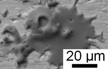
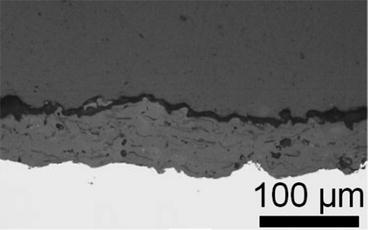
Fig. 9.6
Possible phase development in half melted hydroxyapatite powder particle (Deram et al. [96]. Reprinted with permission. The copyright is held by the referenced source)
Fig. 9.7
Typical hydroxyapatite splat on a metal surface with one large and several smaller pores (Li et al. [98]. Reprinted with permission. The copyright is held by the referenced source)
Fig. 9.8
Plasma spray coating of hydroxyapatite on TiAl6V4 (Narayanan et al. [99]. Reprinted with permission. The copyright is held by the referenced source)
Since the implant material is not heated during the process, plasma spraying is called a cold method, which has the advantage of avoiding metallurgical change or damage to the implant metal [100]. Furthermore, plasma spraying produces coatings with good density and strength and minimised contamination by other elements during the manufacturing process [100].
9.5.2 Plasma Spray Process Parameters
The properties of plasma spray coatings are affected by as many as 50 process parameters [101]. Some parameters can be controlled directly and are called primary parameters, whereas the secondary parameters are determined by the primary parameters (Table 9.6).
Table 9.6
Primary and secondary parameters for thermal spray processes [38]
|
Primary parameters
|
Secondary parameters
|
|---|---|
|
Powder particle morphology
|
Plasma flame temperature
|
|
Powder particle composition
|
Plasma flame velocity
|
|
Powder injection angle
|
Dwell time in plasma flame
|
|
Plasma-forming gas
|
Particle velocity
|
|
Plasma-forming gas flow rate
|
Particle melting
|
|
Current
|
Substrate temperature
|
|
Power
|
Particle quench rate
|
|
Carrier gas
|
Residual stress development
|
|
Carrier gas flow rate
|
Coating thickness
|
|
Standoff distance
|
|
|
Substrate material
|
|
|
Substrate surface properties
|
|
|
Substrate preheating
|
|
|
Traverse velocity
|
The desired, preferred coatings may be manufactured when the parameters that influence the coatings are fully understood. The main parameters of the plasma spray process are power, plasma-forming gas, carrier gas, powder feed rate, standoff distance, and torch traverse velocity.
Plasma power has a major influence on the coating. The power of the spray process needs to be appropriate so that the powder can melt adequately to form the coating. The typical current values used for spraying HA coatings are in the range of 350–1,000 A and are equivalent to 15–60 kW.
Cizek et al. [102] and Guessasma et al. [103] studied the effect of power on the temperature of the plasma flame velocity of the particle. They reported that a high current or power level caused an increase in particle temperature and velocity. Cizek et al. [102] found that high power levels result in an increased flame temperature that gives rise to a greater degree of particle melting. Increasing the power level also increased the velocity of the plasma flame.
A net power increase of 10 kW was observed to cause an increase of 80 °C in particle temperature and an increase of 60 ms−1 in particle velocity. Increased power lead to a decrease in the purity and crystallinity of HA coatings as demonstrated by Tsui et al. [104] and Sun et al. [105]. The findings of Yang et al. [106] contradicted these findings [104, 105] with crystallinity increasing with increasing current. Tsui et al. [104] reported that the porosity level and extent of microcracking decreased with an increase in power. Quek et al. [107] demonstrated that dense, less porous coatings evolved when high currents were employed.
The plasma-forming gas has a major role on the coating properties. There are four main gases used in the plasma spray process: argon, helium, hydrogen, and nitrogen. The choice of the plasma gas depends on many factors, such as the design features of the torch, in particular the electrode materials [108]. However, argon is used as the primary gas because it is relatively inexpensive, is easily ionised, and exhibits inert properties [43]. Argon demonstrates a velocity from 600 to 2,200 ms−1 as reported by Fauchais et al. [109]. Helium, an expensive gas, is used in special cases because it produces a high-temperature plasma flame of high enthalpy. Nitrogen and hydrogen are diatomic gases that give rise to a plasma jet with higher thermal conductivity than monatomic argon, and this helps heat transfer to the feedstock particles. Leung et al. [110] reported that the size and shape of the jet and the momentum that the carrier gas imparts on the powder particles vary with regard to the gases used.
Plasma gas flow rate and power to the plasma torch must be properly balanced or optimised to achieve a stable plasma flame. Gas flow rate has a direct effect on particle velocity, since increasing the gas flow rate during spraying leads to an increase in particle velocity [103]. Guessasma et al. [103] also demonstrated that increasing the gas flow rate from 30 to 50 standard litres per minute (SLPM) resulted in an increase in the average particle velocity from 186 to 269 ms−1 and also a slight increase in particle temperature from 2,516 ± 131 °C to 2,526 ± 203 °C.
The carrier gas transports the powder to the plasma torch and directs it through the central region of the plasma. The velocity of the powder carrier gas is critical, particularly when the powder injector is radial to the plasma flame. A low flow rate would fail to convey the powder effectively to the plasma jet, and a high flow rate may cause the feedstock to overshoot the hottest region of the jet. In a radial injected plasma torch, the powder particles are forced into the plasma flame perpendicular to the direction of the flame. In such a fashion, most particles attain their maximum velocity by passing through the hottest region of the plasma along its central jet axis. The ideal carrier gas flow rate would inject particles into the plasma jet at a momentum similar to that of the plasma jet.
Different carrier gases influence different particle flows into the plasma jet. Argon is most commonly used as the carrier gas [111]. Leung et al. [110] demonstrated that nitrogen exhibited a gas momentum that was 37 % greater than that of argon, and for helium it was 10 % less compared to argon. The nitrogen carrier gas achieved the highest radial distance between the particle trajectory centre and the torch axis due to conferring the greatest momentum. Mawdsley et al. [112] demonstrated that carrier gas flow rate had an effect on the thickness of plasma-sprayed coatings with a high carrier gas flow rate leading to an increase in coating thickness.
The powder, also termed as the feedstock, is transported to the plasma flame by means of a powder delivery tube that may be up to 10 m in length. The delivery rate of the feedstock has two consequences with regard to the coating build-up. Firstly, the powder feed rate influences the coating thickness since an increased flow rate increases the quantity of particles and, therefore, the coating thickness for a set transverse speed. Whereas this is an attribute from the perspective of the manufacturing economics, it should be kept in mind that a very high flow rate may give rise to incomplete melting that results in highly porous coatings. Incomplete melting increases the proportion of the unmelted powders that may bounce off the substrate surface and give rise to a low deposition efficiency. Secondly, it has been reported that the feed rate affects the temperature of the plasma flame. High feed rates infer high carrier gas flows that, with an associated increase in number of particles, may reduce the flame temperature [38].
The distance between the torch and the substrate is termed as the spray distance or standoff distance (SOD). SOD influences the velocity of the particle and the length of time that the particles are exposed to the plasma flame, thus influencing the degree of particle melting. A longer SOD may cause a reduction in the velocity of the droplets during spraying due to the frictional forces from the ambient environment. A shorter SOD would indicate that the substrate experiences more of the heating effects from the plasma flame. Thus, SOD affects the substrate temperature [38]. Kweh et al. [113], for example, demonstrated that coating properties deteriorated with increasing spray distance.
Sun et al. [105] studied the effects of varying SOD from 80 to 160 mm and reported that longer spray distances cause increased particle melting, lower porosity, and a greater number of microcracks. Lu et al. [114] investigated spray distances of 80–200 mm and suggested that at longer spray distances, the particles began to cool and resolidify, thereby allowing formation of a coating with increased crystallinity. Cizek et al. [102] measured the change in temperature and velocity as the spray distance increased from 50 to 150 mm. A decrease in particle temperature of 220 °C and a velocity decrease of 90 ms−1 were observed over this SOD range.
The velocity at which the plasma torch travels is called the torch traverse velocity. Traverse velocity has an effect on cooling, thickness, recrystallisation, and residual stress development. Traverse speeds used for spraying vary greatly, with values ranging from 75 [115] to 750 mms−1 [107] being reported.
9.5.3 High-Velocity Oxygen-Fuel Spraying
The high-velocity oxygen-fuel spray (HVOF) process has been investigated [87, 116] for HA processing. In this process, the feedstock powder is injected in a water-cooled high-pressure combustion chamber that has a long barrel [117]. Oxygen and a fuel gas such as hydrogen [116, 118] combust and establish a high-pressure flame that is able to melt or partly melt the HA feedstock (Fig. 9.9). Coatings produced by means of the HVOF process exhibit good density and strength with low residual tensile stresses. A main advantage is that the feedstock particles do not need to be fully melted to create a high-quality coating [117].
Fig. 9.9
High-velocity oxy-fuel apparatus (Anonymous [118]. Reprinted with permission. The copyright is held by the referenced source)
9.5.4 Coating Phases
There are six possible calcium-containing compounds known in the calcium phosphate system: hydroxyapatite, tricalcium phosphate, tetracalcium phosphate, calcium oxide, calcium pyrophosphate, and oxyapatite (Table 9.7).
Table 9.7
Calcium-containing compounds in the calcium phosphate system (After Gross and Berndt [119]a)
|
Calcium phosphate
|
Chemical formula
|
Short ID
|
Ca/P ratio
|
|---|---|---|---|
|
Hydroxyapatite
|
Ca10(PO4)6(OH)2
|
HA, Hap, HAp
|
1.67
|
|
Tricalcium phosphate
|
Ca3(PO4)2 (as α- or β-phases)
|
C3P, TCP
|
1.5
|
|
Tetracalcium phosphate
|
Ca4P2O94CaO
|
C4P, TTCP
|
2
|
|
Calcium oxide
|
CaO
|
CaO
|
–
|
|
Calcium pyrophosphate
|
Ca2P2O7
|
CPP
|
1
|
|
Oxyapatite
|
Ca10(PO4)6O
|
OA
|
1.67
|
Not every compound appears in HA coatings since these are controlled by the spray process and parameters. The amorphous and the crystalline phases of HA are dominant. Alpha and/or beta phases of tricalcium phosphate and tetracalcium phosphate are often also present. The amorphous HA phase may develop instead of a crystalline phase due to the rapid solidification conditions during the splat quenching process where cooling rates of 1 × 10⁶ degrees per second may exist. Thus, the HA does not have adequate time to crystallise [120, 121].
It has been mentioned previously that the spray parameters gave rise to coating layers that may exhibit variable thickness. A decrease of the layer depth, for example, by employing a low feedstock delivery rate, leads to higher cooling rates since heat can be transferred more rapidly away from the splat, thus leading to HA with an amorphous character (Fig. 9.10). This same effect may be achieved by altering the spray angle so that the impacting particle is more likely to smear across the substrate surface. Increasing the droplet heat has the same effect since the particle viscosity is decreased so that there is more fluid upon flattening against the implant surface. Alternatively, the thermal spray process may be performed at a higher velocity, e.g. affected by a higher primary gas flow that increases the cooling rate by flattening the coating layers.
Fig. 9.10
Causes for an increase or decrease of the amorphous phase in a plasma-sprayed hydroxyapatite coating (Gross et al. [121]. Reprinted with permission. The copyright is held by the referenced source)
It is possible to form an oxide layer on the implant metal surface due to heating effects caused by the initial particle layers. These layers, together with the thermal flux from the plasma, may exhibit increased cooling rates due to enhanced heat transfer and thereby increase the proportion of the amorphous phase.
An increase of the surface roughness of the implant material will reduce the flattening response of splats and, therefore, reduce the cooling rate. It is more likely that crystalline phases will evolve under such conditions.
Stay updated, free dental videos. Join our Telegram channel
VIDEdental - Online dental courses
