Introduction
The biomechanics of a continuous archwire inserted into multiple orthodontic brackets is poorly understood. The purpose of this research was to apply the birth-death technique to simulate the insertion of an orthodontic wire and the consequent transfer of forces to the dentition in an anatomically accurate model.
Methods
A digital model containing the maxillary dentition, periodontal ligament, and surrounding bone was constructed from computerized tomography data. Virtual brackets were placed on 4 teeth (central and lateral incisors, canine, and first premolar), and a steel archwire (0.019 × 0.025 in) with a 0.5-mm step bend to intrude the lateral incisor was virtually inserted into the bracket slots. Forces applied to the dentition and surrounding structures were simulated by using the birth-death technique.
Results
The goal of simulating a complete bracket-wire system on accurate anatomy including multiple teeth was achieved. Orthodontic forces delivered by the wire-bracket interaction were 19.1 N on the central incisor, 21.9 N on the lateral incisor, and 19.9 N on the canine. Loading the model with equivalent point forces showed a different stress distribution in the periodontal ligament.
Conclusions
The birth-death technique proved to be a useful biomechanical simulation method for placement of a continuous archwire in orthodontic brackets. The ability to view the stress distribution with proper anatomy and appliances advances our understanding of orthodontic biomechanics.
Despite the use of fixed appliances for over 100 years, our understanding of orthodontic biomechanics is still limited. Prediction of the forces and moments transferred to the dentition by a continuous wire is generally limited to a 2-dimensional force diagram containing only 2 or 3 teeth without accurate anatomy (eg, periodontal ligament [PDL] and alveolar bone). Free body diagrams assuming rigid body motion of archwires and teeth have been used to estimate forces and moments. Beyond this point, the system frequently becomes indeterminate.
New advances in 3-dimensional (3D) technology, such as computer-aided design and computerized tomography imaging, allow for a more accurate description of dental anatomy. Although the associated force transfer through the dentition during orthodontic treatment frequently is statically indeterminate, these systems can be solved by incorporating the principles of solid mechanics. However, current finite element analysis that could predict applied forces with a continuous archwire is rarely combined with 3D multiple tooth systems.
Several appliance systems (Invisalign: Align Technology, Santa Clara, Calif; Insignia: Ormco Co, Orange, Calif; Incognito: 3M Unitek, St. Paul, Minn; and SureSmile: Orametrix Inc, Richardson, Tex) based on computer-aided design and computer-aided manufacturing already have computer models for appliance design purposes, but they do not focus on portraying forces produced by the appliances or transferring these forces to accurate anatomy. Huiskes and Chao, Lin et al, and Cattaneo et al have reported that accurate anatomy of the patient-based models is important. Field et al concluded that multiple teeth should be included in a model to allow the transfer of forces through both contact areas and interproximal tissues. Proper morphology of appliances and ligation methods are important as well to accurately predict responses in 3 planes of space.
Current simplified finite element modeling often applies a point force to simulate orthodontic appliances rather than including the appliances. Kim et al, Mo et al, and Sung et al included brackets and wires to study the retraction of the anterior segment; however, the teeth were bonded together at the contact points and between the wire and the braces rather than individually ligated to the archwire with contact interfaces. These point-force models did not recreate the unloading force that is expressed by orthodontic wires in the clinic.
In this study, we propose a new model that includes the proper morphology of the teeth, surrounding tissues, and appliances. It is unique in that it examines the behavior of an activated continuous archwire that includes individual ligation of each tooth in the model rather than an archwire that, for modeling purposes, is assumed to be indistinguishable from “brackets” (bonded interfaces) as in the point-force models. Much as fence posts secure the fence rails or railroad ties secure the railroad tracks, this new model includes the brackets to secure the continuous archwire to allow the teeth to slide and thus has been named the rail-and-brace (ie, fence posts or railroad ties) model. Generating this more inclusive model will allow more accurate prediction and quantification of forces from appliances used in modern practice.
To simulate the effect of including the bracing structures (fence posts or railroad ties) in the model, a computer technique called the “birth-death” technique (ANSYS, Canonsburg, Pa) was used. It will be discussed in detail below but, in brief, refers to a 2-step technique of initially ignoring 1 aspect of the model (by “killing” it with the “death” step) and then adding it back in (the “birth” step). This is necessary because, in the virtual or computational world, unrealistic or impossible actions can occur, such as the step bend passing through a bracket as if the bracket were not present. In this model, the bracket is initially “killed” in the “death” step when the archwire is activated. Forces that result from the bracket’s engaging the step bend of the archwire are ignored until the bracket is added back into the model in the “birth” step.
The purpose of this study was to simulate the activation of a step bend in an orthodontic archwire by using a virtual 3D finite element model with complete orthodontic appliances on 4 teeth. The specific aims were to place complete standard bracket and wire systems on accurate anatomy including multiple teeth, and to transfer and analyze the forces throughout the dentition and surrounding structures by clinically realistic wire bends with the birth-death technique.
Material and methods
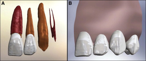
A virtual maxilla, including cortical bone, trabecular bone, and sinuses, was constructed by sequentially stacking cone-beam computerized tomography slices of a dentate maxilla. In a similar manner, the dentition was built by using microcomputed tomography templates by identifying the pulp, dentin, and enamel on sequential slices. The PDL (0.25 mm thick) and the lamina dura (0.5 mm thick) were added around each tooth with software (Solidworks, Concord, Mass). The models were merged by Boolean operations. Figure 1 shows the details of the model.

Three-dimensional computer-aided design models of 0.022-in slot, standard (0° tip, torque, and rotation) labial brackets on the maxillary right central and lateral incisors, canine, and first premolar were constructed and placed so that the gingival base of each slot was on the same reference plane. The bases of the bracket pad were adjusted to ensure a smooth interface with the facial surface of the tooth. No cement layer was included because it was deemed to have little effect unless a stress sufficient to debond the bracket was achieved.
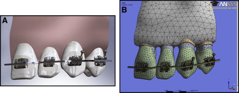
The lingual and occlusal walls of the brackets were used as reference planes to create a passive 0.019 × 0.025-in stainless steel archwire in Solidworks ( Fig 2 , A ). By using the passive wire as a starting point, a 0.5-mm intrusion bend was formed at the lateral incisor position. Bends were placed over a 1.0-mm section of wire in the adjacent interproximal areas. Two 0.010-in cylinders were added at either end of the slot opening to simulate passive stainless steel ligature wires that hold the archwire inside the bracket slot. The ligatures were placed to touch but not to overlap the archwire, and were combined with each bracket to form 1 body. The complete computer-aided design model was established with the Solidworks software, and the solid body information was saved in Initial Graphics Exchange Specification (IGES) format.

The IGES geometry files were imported into ANSYS version 13.0 Workbench. By using ANSYS Design Modeler, the individual solid bodies (bracket, ligature wire, enamel, dentin, pulp, PDL, lamina dura, and trabecular and cortical bones) were merged into a multibody part, allowing for conformal meshing of the model. Conformal meshing creates shared nodes at the interfaces, providing accurate modeling for bonded heterogeneous biologic structures. The archwire was not merged into this multibody part, allowing for frictionless contacts areas with nonconformal meshing and wire movement relative to the brackets. In addition, the interproximal contacts were also considered frictionless, so that the teeth were allowed to move relative to each other. All other interfaces were rigidly bonded by using the penalty method. Proper material properties were assigned for enamel, dentin, pulp, PDL, cortical bone, trabecular bone, and stainless steel ( Table I ), with the assumption that all materials were isotropic and linearly elastic. The final model was meshed by using the tetrahedral 10-node element, except for the swept hexahedral 8-node element in the archwire, and consisted of 238758 nodes and 147747 elements ( Fig 2 , B ). The model was fixed at the ends of the archwire and at the cortical and trabecular bone at the midline and distally to the first premolar.
| Poisson’s ratio | Young’s modulus (Pa) | |
|---|---|---|
| Enamel | 0.41 | 8.00E + 10 |
| Dentin | 0.31 | 1.80E + 10 |
| Pulp | 0.3 | 1.75E + 08 |
| PDL | 0.3 | 1.75E + 09 |
| Cortical bone | 0.31 | 1.37E + 10 |
| Trabecular bone | 0.3 | 1.37E + 09 |
| Stainless steel | 0.3 | 2.00E + 11 |
The static equilibrium equations were solved under the large displacement assumption. Deformation of the system was evaluated to confirm the validity of the solution.
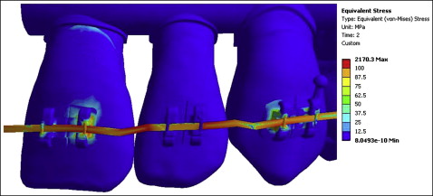
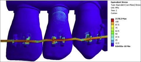
To simulate the insertion of an active archwire, a 2-step computer technique called “birth and death” was used. Since the archwire with the 0.5-mm step bend initially overlaps the lateral incisor bracket, the first step involves displacing the wire into the bracket slot. This requires intentionally ignoring the interaction between elements in the contact area involving the wire and bracket, known as a “kill” or “death” step. Displacement of the wire into the slot removes the overlap with the bracket and loads stored energy in the wire and adjacent teeth ( Fig 3 ). With this solution, the deactivated elements of the contact area were reactivated, known as an “alive” or “birth” step. Then, in this second step, the displacement of the wire was relaxed, loading the lateral incisor ( Fig 4 ). This “birth and death” function allows elements to change status in contact areas at a later step in the simulation; this is required for insertion of active archwires.


Static structural solutions were converged at 2 steps (element kill and element birth), and the results were generated for reaction forces, maximum and minimum principal elastic strains, equivalent elastic strain, maximum and minimum principal stresses, equivalent (von Mises) stress, and total deformation. Convergence of the solution was checked by using the Newton-Raphson method.
To compare the birth-death technique with previously published point-force models, a second model was generated with identical anatomy. In this model, the archwire was removed, and point forces were applied by using the reaction forces calculated from the birth-death model. Stress distribution through the dentition and the surrounding tissue was compared with the birth-death model.
Results
The solution converged for both steps in the birth-death model. Before the contact area was activated in the lateral incisor bracket, displacement of the wire placed stress on the canine and central incisor brackets ( Fig 3 ). The lateral incisor was not loaded in this step because the elements were deactivated. Additionally, more stress was seen in the central incisor bracket than in the canine and premolar brackets, since the activation force was primarily placed on 1 bracket instead of evenly distributing to 2 brackets. Once the contact was reactivated, the stress increased in the lateral incisor bracket and decreased in the adjacent brackets ( Fig 4 ). The final solution showed higher force levels ( Table II ) in the lateral incisor bracket than in the central incisor and canine brackets.
| Central incisor | Lateral incisor | Canine | |
|---|---|---|---|
| Step 1 | 40.1 | 0 | 18.8 |
| Step 2 | 19.1 | 21.9 | 19.9 |
Stay updated, free dental videos. Join our Telegram channel

VIDEdental - Online dental courses


