Non-surgical root-canal treatment
Principles of root-canal system management
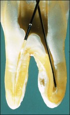
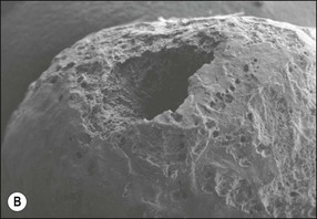
The treatment of choice for management of periapical disease is the elimination of microorganisms and their products from the root-canal system. Microorganisms may be found in suspension in the root-canal system in the apical part but they mostly colonize canal walls and dentinal tubules to a variable degree up to the apical foramina. A microbial biofilm with a variable thickness and properties coats the dentinal wall (Fig. 8.1); where the pulp chamber is exposed, the coverage is continuous but, in teeth with intact pulp chamber walls, the coverage is patchy. Bacteria penetrating the dentinal tubules may be considered to be extensions of the main canal biofilm resulting in a three-dimensional form that may resemble a “hairy worm”! In addition to the biofilm, there is also a variable penetration into the tubules of bacterial products and toxins, such as lipopolysaccharide. The complex three-dimensional form of root-canal systems adds to the difficulty of the task of decontaminating its surface.
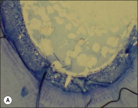
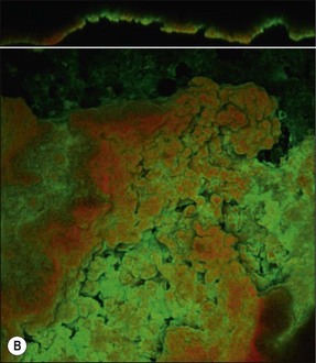
Fig. 8.1 (a) A microbial biofilm covering the canal wall; (b) CLSM images (×40) of biofilm stained with Pisum sativum lectin, showing the distribution of extracellular polysaccharide matrix from cross-sectional and surface perspectives
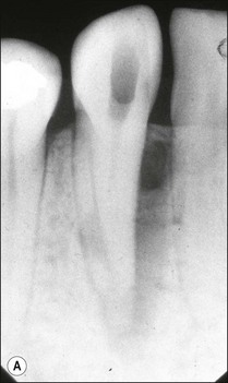
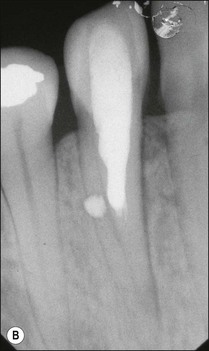
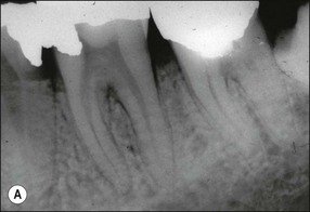
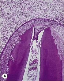
It is in fact impossible to sterilize the root-canal system with available equipment, materials and techniques. It is therefore fortunate that sterility is not a precondition to successful outcome of root-canal treatment. Root-canal treatment procedures work because the reduction in microbial and microbial product content of canal systems together effect a collective diminution in their pathogenicity, which promotes periradicular healing. The part played by altered pathogenicity in periapical healing is demonstrated by the presented case, in which despite lack of direct access to the apical part of the root-canal system, almost complete periapical healing was brought about (Fig. 8.2). The precise mechanisms leading to complete biofilm eradication are not fully understood, but it is clear that both the mechanical and chemical components of canal preparation play a role.
Root-canal system management may, therefore be thought of in terms of:
Principles of mechanical intraradicular preparation
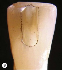
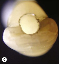
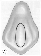
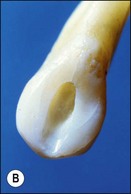
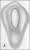
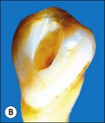
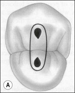
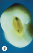
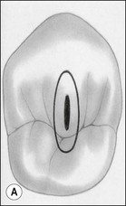
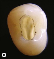
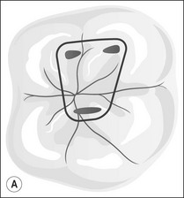
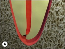
The purpose of the mechanical aspect of intraradicular preparation is to create access to the root-canal system. The aim of this extension of the coronal access cavity or to name it by its function, the radicular access cavity (conventionally known as canal preparation) is to obtain and maintain “patency” to the apical part of the root-canal anatomy (Fig. 8.3). The shape of the radicular access cavity is a general tapering form that may have a circular (Fig. 8.4a) or slightly eccentric cross-sectional (Fig. 8.4b) configuration. The final form depends on the initial shape of the root-canal system and the form imposed by the mechanical preparation, which is dictated by the instruments and the manner in which they are manipulated. The mechanical preparation typically involves using metal instruments of graded sizes to:
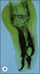
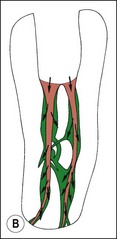
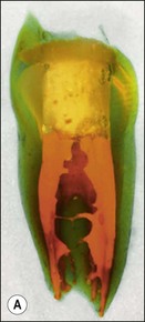
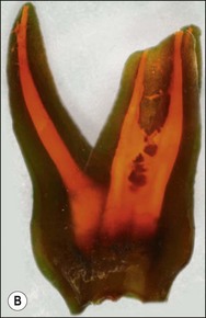
Fig. 8.3 (a,b) Canal preparation (orange channels) as a radicular access to the root canal system (green) in (b)
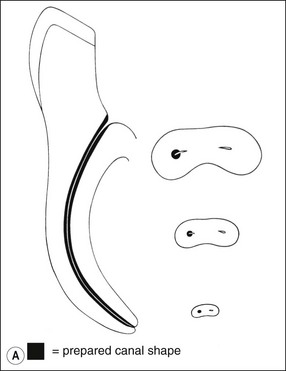
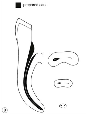
Fig. 8.4 Longitudinal and transverse sections showing the canal (a) before and (b) after preparation
• negotiate instruments of sufficient size to the apical terminus of the root-canal system without losing patency
• shape the radicular access to a predefined taper, sufficient to allow antibacterial agents and root-filling materials to be delivered to the full extent (all surfaces) of the root-canal system in a controlled way.
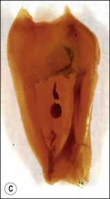
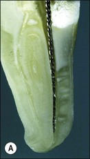
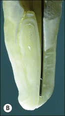
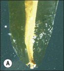
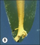
These goals should be achieved by controlled removal of intraradicular dentine such that the original shape and curvature of the main root canal(s) are retained (Fig. 8.5). This together with a relatively conservative final preparation size helps to ensure that the root is neither excessively weakened nor perforated. In narrow uncomplicated canal systems, the mechanical preparation alone may be sufficient to effect almost complete removal of the microbial biofilm (Fig. 8.6). However, this is a rare achievement even in anterior, single-rooted teeth (Fig. 8.7). The truth is that there is always a variable proportion (30–50%) of residual non-instrumented surface in the root-canal system (Figs 8.3, 8.8, 8.9). This finding suggests that it is not necessary to file or plane all surfaces of the root-canal system for a successful outcome; therefore, the adjunctive chemical preparation must play the important role of reaching all surfaces.
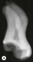
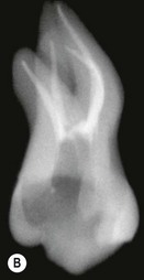
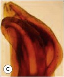
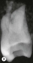
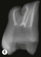
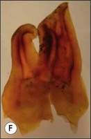
Fig. 8.5 (a–f) Controlled removal of intraradicular dentine with original shape and curvature of main root canal(s) retained (courtesy of Imran Azam)
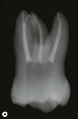
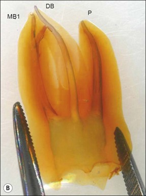
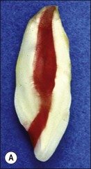
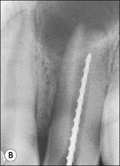
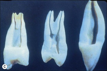
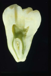
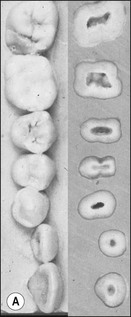
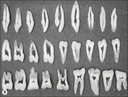
Fig. 8.7 (a) Irregular wide-root canal in maxillary canine; (b) wide, “blunderbuss” canal in an incompletely formed root; (c) sectioned teeth showing variable canal system shape
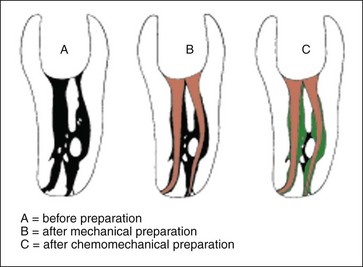
Fig. 8.8 These diagrams are reproduced from the cleared tooth shown in Figure 8.3; (a) before preparation; (b) after mechanical preparation; (c) after chemomechanical preparation
Principles of chemical intraradicular preparation and intra-appointment root canal irrigation
In order for the chemical agent to reach all surfaces of the root-canal system, a sufficient path must exist and the flow of the fluid irrigant must be facilitated. This requires that obstructions in the path have to be cleared. Prior to mechanical preparation, the root-canal system may have pulp tissue in various states of disintegration, dystrophic pulp calcification or pulp stones, and bacterial biofilm coating walls and disintegrating tissue (see Fig. 8.1). The process of mechanical preparation would disrupt and displace such contents as the canal was being enlarged by dentine removal. The dentine chips generated from the shaping process would add another element to the canal content. This heterogeneous mass of organic and inorganic tissue needs to be flushed out of the canal system.
1. the challenge of delivering the irrigant to the narrow and distant apical anatomy, as well as all the ramifications diverging off along the length of the root-canal system (Fig. 8.10)
Fig. 8.10 Ramifications diverging off along the length of the root canal system (courtesy of Michael Jones)
2. the challenge of delivering irrigant to the depths of the multilayered, three-dimensional microbial biofilm with its polysaccharide matrix protection (see Fig. 8.1).
Therefore, this implies that the final stage of irrigation consists of delivering the irrigant to all parts of the root-canal system, while allowing sufficient time for chemical penetration and dissolution. Wider and larger radicular access cavities may allow better delivery of chemical agents to the uninstrumented surface, especially the all important and highly complex apical anatomy. However, a balance has to be struck between the desire to improve delivery of chemical agents through larger preparations and that to maintain the strength of the tooth, which requires maintenance of the bulk of dentine (Fig. 8.11).
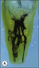
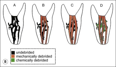
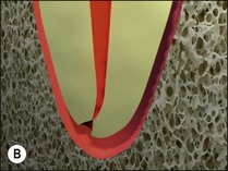
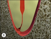
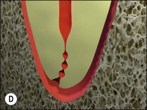
Fig. 8.11 (a,b) Effect of narrow and widely tapered preparations on complex canal anatomy: (A) before preparation; (B) after narrow-taper preparation; (C) after wide-taper preparation; (D) after mechanical preparation and use of irrigant with ability to dissolve debris and destroy bacteria
The first problem may be overcome by enlarging and shaping the radicular access sufficiently to allow the irrigant to be delivered to the apical anatomy using an appropriately sized, narrow-gauge “endodontic” needle (Fig. 8.12) or some form of agitation. The inference is that in naturally wide, straight canals, minimal mechanical preparation should be required (Fig. 8.13).
The second problem may be overcome by using a high enough concentration or alternatively sufficient volume of irrigant through continuous replenishment to give long-lasting chemical potency. The combined action of mechanical and chemical cleaning is more efficient than either method alone, and allows a more conservative canal preparation as reliance on dentine removal for decontamination (a forlorn hope) is reduced. This is the so-called “chemomechanical” method of root-canal system preparation.
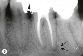
Canal preparation in teeth requiring pulpectomy, that is, vital pulp removal, has similar but not identical aims. The concern in such teeth is to remove not microorganisms but pulp tissue which may, in due course, become necrotic and possibly infected (Fig. 8.14). In the case shown, the uninstrumented apical portion of the distal canal has resulted in the development of incipient periapical disease. It is therefore useful if the selected irrigant both dissolves organic tissue and destroys microorganisms.
Phase 1 – during canal negotiation and apical enlargement – the main requirements are to lubricate the smooth penetration of the instruments in the tight channels to the apical terminus and flush out generated debris
Phase 2 – during mechanical shaping to a final taper – the requirement is mainly to flush out generated debris and to dissolve attached and adherent organic fragments and to facilitate their flushing out
Phase 3 – after mechanical shaping is complete – the main requirement is to deliver the chemically active irrigant to all canal surfaces through active or dynamic irrigation.
Principles of chemical intraradicular preparation and interappointment intracanal medication
1. Be able to kill all root canal bacteria with a long-lasting antibacterial effect
2. Not be inactivated by the presence of organic material
3. Be able to help degrade residual organic material, including pulp tissue or microbial biofilm
4. Not be irritating to periapical tissues or have systemic toxicity
5. Be able to induce regeneration of periapical tissues
6. Not affect the physical properties of the temporary access cavity restoration or be able to diffuse through the temporary seal
Principles of root-canal system obturation
In the past, the main emphasis was placed on establishing an apical “seal” (Fig. 8.15). However, in recent years, the importance of the coronal seal has been appreciated more fully. The purpose is therefore to “seal” the entire root-canal system, including the coronal entry. Cases have been reported which demonstrate that it is possible to achieve resolution of periradicular lesions following root-canal preparation and coronal seal alone or even spontaneous resolution of a lesion following caries removal and placement of a coronal restoration (Fig. 8.16)! Therefore, obturation of the root-canal system should begin with the root-canal filling and finish with an integrated, well-designed and executed coronal restoration (Fig. 8.17).
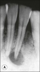
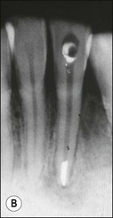
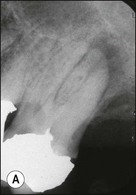
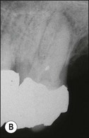
Fig. 8.16 (a,b) Spontaneous resolution of a lesion following caries removal and placement of a coronal restoration in a tooth with a necrotic pulp
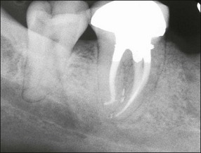
Fig. 8.17 Postoperative radiograph of non-surgical root canal treatment on lower molar tooth with well-designed and integrated coronal restoration
The aims and objectives of obturation therefore are:
• to establish a barrier to the passage of microorganisms from the oral cavity or root-canal system to the periradicular tissues
• to “entomb” or “incarcerate” and isolate any microorganisms that may survive the shaping and cleaning process
• to prevent leakage into the canal system of potential nutrients that would support microbial growth
• to reduce the risk of bacterial movement or fluid percolation into the canal system space from the gingival sulcus or periodontal pockets.
Coronal access cavities
Principles of cutting a coronal access cavity
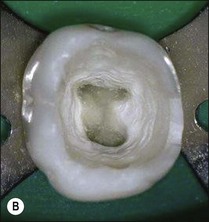
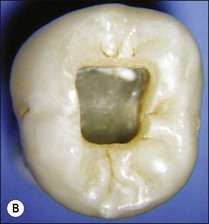
1. Remove the roof of the pulp chamber so as to provide good visual and tactile access to the entrances of the main root canals (Figs 8.18, 8.19). It is a common fault to leave remnants of the pulp chamber roof together with some pulp remnants (Fig. 8.20)
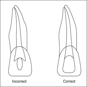
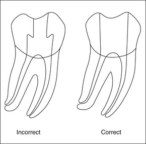
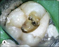
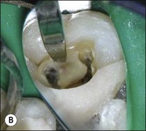
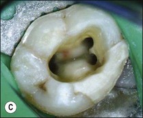
Fig. 8.20 (a) Mandibular first molar with incomplete removal of pulp chamber roof; (b) roof of pulp chamber being removed by ultrasonic tip; (c) roof of pulp chamber removed
2. Provide straightline access to the first curve in the root canal (Fig. 8.21). The walls of the coronal access cavity should not deflect an instrument placed into a canal
3. Avoid damage to the floor of the pulp chamber, so as to avoid perforation of the pulp chamber floor and make it easier to locate the canal entrances (Fig. 8.22). The natural shape of the floor funnels and tends to guide an instrument into the canal orifice
4. Conserve as much tooth substance as possible to prevent weakening and fracture of the remaining tooth consistent with the above aims (Fig. 8.23)
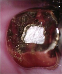
5. Provide coronal and apical resistance form so that the temporary access cavity seal remains intact until the final restoration is placed (Fig. 8.24).
Cutting the coronal access cavity
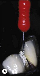
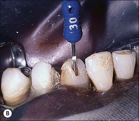
Initial penetration into dentine is made with a tungsten-carbide, domed-fissure, cross-cut bur aimed towards the largest part of the pulp chamber. When penetration to dentine is through a porcelain crown or enamel, a round diamond bur is used to cut through these brittle materials first before changing to a tungsten-carbide bur to cut through the metal or dentine beneath (Fig. 8.25). Once the roof of the pulp chamber has been penetrated, a safe-ended, tapered, diamond bur, or similar-shaped tungsten-carbide bur, is used to reduce the risk of damaging the pulpal floor while the roof is removed. The depth of penetration can be judged by holding the hand-piece containing the bur against the parallel view preoperative radiograph, or using the measuring tool available on digital radiographic, systems (Fig. 8.26). Older teeth have smaller pulp chambers and, therefore require a smaller access cavity. Additionally, the floor may have calcified pulp tissue attached and care must be taken to remove it (Fig. 8.27). Younger, immature teeth have large pulp chambers and probably should not have their entire roof removed to avoid unnecessary weakening of the tooth (Fig. 8.28). Thought must be given to the type of permanent restoration that will be used afterwards as this will alter the shape and approach to cutting the coronal access cavity. For example, in the case of an onlay, the walls of the access may be reduced before the canal-root treatment is carried out or, in the case of an anterior tooth which is to be crowned and is lingually inclined, consider access from the labial aspect (Fig. 8.29). Radiographs (Fig. 8.30) show that straightline access can be just as effective from the buccal aspect as from the lingual.
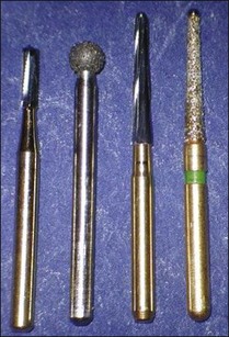
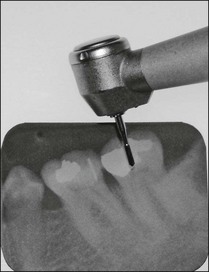
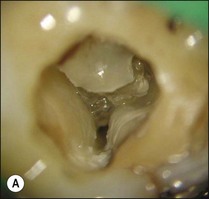
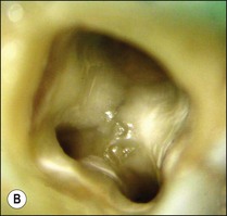
Fig. 8.27 (a) Calcified tissue and pulp remnants; (b) pulp chamber thoroughly cleaned and canals prepared
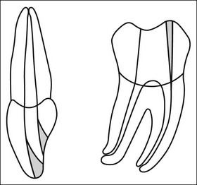
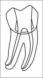
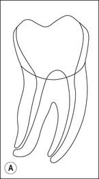
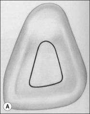
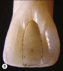
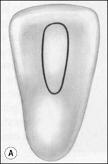
Outline shape
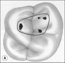
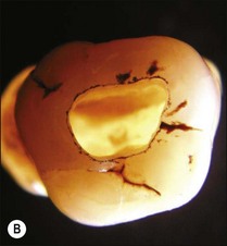
The outline shape of coronal access cavities is dictated by the shape of the pulp chambers which, in turn, follow that of the tooth in cross- or longitudinal section (Fig. 8.31). The standard shapes of coronal access cavities for different tooth types are given in Figures 8.32–8.39. The actual size and shape of the cavity is dictated by the size and shape of the pulp chamber and will therefore, tend to be smaller in older patients.
Location of the canal terminus and determination of canal and working length
Point of termination of canal preparation
It is impossible to determine the apical extent of contamination of a root-canal system clinically; it is best to assume contamination up to the apical foramina in all cases with necrotic pulps and to clean the canal system to this/these point(s). It is safest to clean to the apical termination of root canals even in cases where the tooth is vital but failure to do so will not jeopardize success in such cases. However, it is crucial to ensure that instrumentation and treatment materials do not extend beyond the root-canal system as this may reduce the prospects of a successful outcome.
Clinical location of the root-canal system terminus/termini
Root-canal systems have been classified in different ways, including by the number of termini they exhibit (see Chapter 1). Locating the apical termini of the root-canal system exactly is an art rather than a precise science. Several methods are used to triangulate the terminal point(s) of the root-canal system, they include:
Each of the methods is analysed independently first and then a way of combining them offered.
Radiographic method
The first problem is that the root-canal system often ends in an apical delta so that there is not just one but several apical foramina. The diagnostic endodontic file will pass into only one of these (Fig. 8.40).
The second problem is that the radiographic view with a file in the canal provides a two-dimensional picture of a three-dimensional root-end, in which the file may be disposed in any plane within a 360° circumference (Fig. 8.41). Unless a single root-canal system exit is disposed at exactly right angles to the X-ray beam and film, the radiographic technique can never estimate the position of the apical terminus accurately.
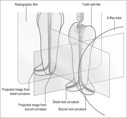
Fig. 8.41 Line diagram showing radiographic views of file in a root that curves distally or buccally
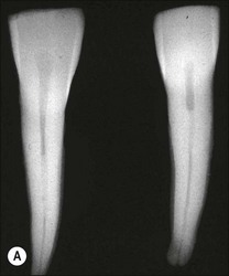
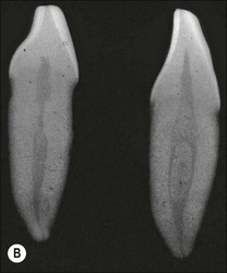
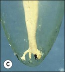
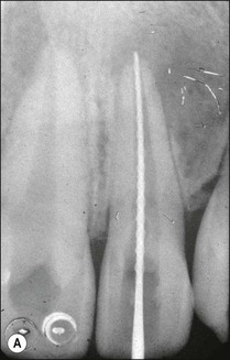
The traditional protocol for canal length determination using radiographic technique alone is as follows. An estimate of the approximate length of the tooth is made from a preoperative parallel radiograph (Fig. 8.42). A file is placed in the root canal about 1 mm short of this estimated length, ensuring that a coronal reference point is selected that is reproducible, stable and durable. The file should be large enough to be visible on the radiograph (e.g. size 10 but size 08 may also suffice). It is best not to commence apical instrumentation before understanding the location of the canal terminus, as irreversible damage is easily incurred at the early stages. A parallel radiograph is then taken (Fig. 8.42b). In teeth with multiple canals, diagnostic files should be placed in all canals and a single view taken to minimize exposure to radiation (Fig. 8.43). Canals may exit on the root surface at a variable distance and position from the root tip and it is impossible to judge the three-dimensional distribution of apical foramina satisfactorily from radiographs (Fig. 8.44). This pair of images shows three roots, with files that appear flush with the radiographic root tip but which are actually extended past the apical foramina. Figure 8.45 shows a case taken from a clinical study, in which a cemented file that is apparently flush with the root tip is actually extended well beyond the apical foramen. An average distance of 1 mm short of the radiographic apex is widely accepted as a reasonable estimate of the terminal position of the canal, but this may be inaccurate by up to 3 mm (Fig. 8.46).
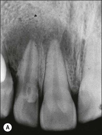
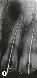
Fig. 8.42 (a) Preoperative parallel view radiograph; (b) periapical radiograph with diagnostic files
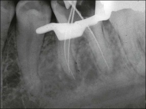
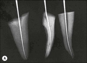
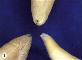
Fig. 8.44 (a,b) Discrepancies between radiographic images of files and reality in relation to the root apex
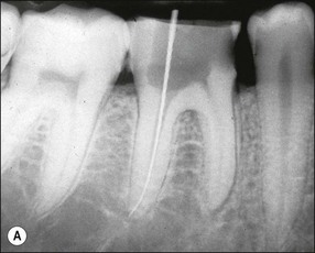
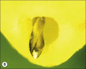
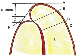
Fig. 8.46 Relationship between root tip, apical foramen, and apical constriction: A = root apex; B = apical constriction; C = root canal; D = cementum; E = dentine; F = apical foramen
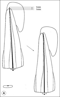
1. In most cases, the tip of the file will be short of the radiographic apex. This is often accepted as the length of the canal if the distance is within 1 mm (as in the lateral incisor: Fig. 8.47a). If the discrepancy is greater than 1 mm, then the distance between the file tip and the radiographic apex should be measured and 1 mm subtracted from this measurement (as in the central incisor: Fig. 8.47a). This residual discrepancy is added to the length of the diagnostic file to give the estimated length of the canal (Fig 8.47b,c).
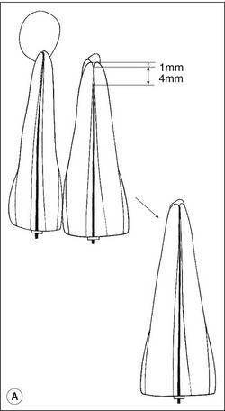
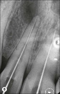
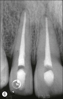
Fig. 8.47 (a) Diagram reproduced from Figure 8.42b. Correct length in 12 accepted. Short length in 11 is corrected; (b,c) adjusted diagnostic files and final root fillings
2. In some cases, the file may be longer than the radiographic apex, in which case the distance between the file tip and a point 1 mm short of the radiographic apex should be measured (Fig. 8.48). Subtracting this figure from the length of the diagnostic file will give the length of the canal.
Electronic apex-locator method
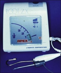
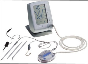
Electronic apex locators (Fig. 8.49) in theory enable the location of the true position of the apical terminus, utilizing the fact that root canals, in common with other tubes with one end immersed in an electrolyte solution, exhibit certain electrical characteristics that are relatively constant.
The parameter of importance is the abrupt change in impedance of the root canal as the terminus is approached and bypassed. The impedance in question is measured between a point along the length of the root canal and the oral mucosa (Fig. 8.50). Introduction of electrolytes into the root canal causes the impedance to drop and the gradient of impedance along the canal to decrease. The impedance value at the apical foramen, that is, between the periodontal ligament and the oral mucosa, measured via the root canal is a relative constant. This value is used to calibrate commercial EALs, but the impedance characteristics of the canal coronal to the apical foramen are not factored in. EALs should therefore always be used to achieve the “zero” reading for greatest accuracy and not any point short of this.
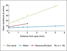
Fig. 8.50 Electrical impedance of root canals at different distances from the apical foramen with water-filled and dry canals. Also shown is the average calibration of a typical apex locator
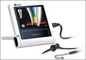
EALs work by applying an alternating current between two electrodes, one of which is attached to the file and the other via a clip to the lip or cheek mucosa (Fig. 8.51a,b). The frequency of this current, which also influences impedance, is usually fixed in a given make of instrument but differs between makes. As the file is passed down the canal, the EAL measures the impedance and compares the value with its calibrated standard. A countdown scale indicates a “zero” or “apex” reading when the calibrated value is matched (Fig. 8.51c–e). All currently available conventional EALs use this principle but display the information differently. The current generation of EALs has overcome the problem with electrolytes in root canals by measuring the impedance at multiple current frequencies. The Root ZX (J Morita, Kyoto, Japan) (see Fig. 8.49) compares the ratio of impedance at two frequencies to derive the apical position. The Apex Finder AFA (Discontinued) claimed to derive the information from five different frequencies. The Elements Diagnostic Unit (SybronEndo) (Fig. 8.52) claims to be a fourth generation apex locator measuring resistance and capacitance separately rather than the resultant impedance; it then putatively searches for comparative values in a lookup matrix generated from in-vivo studies. The Raypex® 5 (VDW) (Fig. 8.53), which also uses multiple frequencies, claims to be a fifth generation apex locator with greater accuracy.
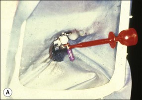
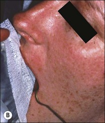
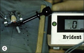
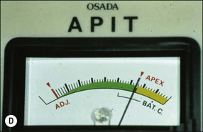
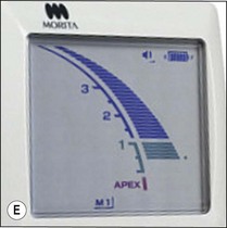
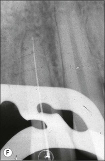
Fig. 8.51 (a,b) Connection of electrodes to file and cheek; (c–e) apex indication in different apex locators; (f) file placed to length indicated at “zero” by apex locator
The accuracy of different models of EALs has been tested clinically and shows slightly variable results for the same EALs in different studies and for different EALs in the same study. These differences may be attributed to many factors, including conditions of use and calibration of the instrument. Each instrument requires practice in use to become familiar with its idiosyncrasies before it can be used with confidence. EALs are reliable but should not be relied upon in all circumstances. If there is any doubt about the reading, a radiograph must be taken. Potential problems in use include short-circuiting if the file touches a metal restoration, if the canal contains excessive moisture, or if the size of the file is too small. Clinicians should, having used the EAL to obtain a “zero” length reading, take a check radiograph (see Fig. 8.51f). The greatest advantage of the EAL, is that having obtained and confirmed this base-line reading, the working length and patency may be monitored continuously throughout canal preparation with each file placed to length or just short. This confers tremendous confidence to the clinician during the procedure.
Tactile method
Some clinicians claim that it is possible to gauge the apical constriction of the root-canal system by tactile sense. There are several problems with this claim. First, not all teeth possess an apical constriction due to the presence of apical resorption caused by apical periodontitis (Fig. 8.54). Second, the ability to gauge the apical constriction relies on the pre-existence of a natural canal taper that has a minimal constriction only at the termination of the canal; Dummer et al (1984) observed four distinct patterns of apical constriction (Fig. 8.55). Third, the tactile detection of the apical constriction relies upon the selection of a file size that will first bind only at the apical constriction. Given that the size and anatomy of the apical constriction varies considerably, this method is reliant upon several preconditions, as well as the fortuitous selection of the correct instrument size. Taking these factors collectively, it is highly unlikely that tactile sense alone can be used to gauge the position of the apical terminus, although it has been shown that the chances are improved by a step-down preparation approach.
Determination of working length
Once the length of the canal has been determined, it is necessary to decide whether the series of root-canal instruments will be set to that length or short of it. Many factors dictate the length to which instruments will be used in the canal. The goal of the negotiation phase of canal preparation is to enlarge the canal to at least size 30 (ISO) just short of the canal terminus. That is, to preserve the original size of the apical foramen as far as possible. If the canal is to be prepared to a wide non-ISO taper (0.06 plus), then it is considered that preparation to size 20 or 25 may be sufficient. The optimal size of the apical preparation is size 30. If the operator is very meticulous, the length to which the canal is prepared can be controlled />
Stay updated, free dental videos. Join our Telegram channel
VIDEdental - Online dental courses


