Chapter 9
Interpretation of the Preoperative CT Scan: The Relationship of Anatomy and Occlusion to Implant Placement
The use of endosseous implants to create an aesthetic and biomechanically stable dental prosthesis depends on appropriate sizing and three-dimensional placement of the implants in a relationship that maximizes load distribution. The analysis of the relative intensity, direction, and frequency of forces placed on the plane of occlusion includes consideration of the curves of Wilson and Spee, overbite, overjet, and guidance in excursions from maximum intercuspal position. It is the sum of this loading calculation that gets transmitted through the occlusal plane to the abutments and then in turn to the tooth-ligament or implant-bone attachment (Figure 9.1). The mechanical resistance of these different systems of attachment can be reduced to the following axiom: Compressive forces are well tolerated; lateral forces can be destructive.
Figure 9.1 (A) Implant-abutement-bone relationship. (B) Natural tooth tissue relationships notch on buccal (monkey).
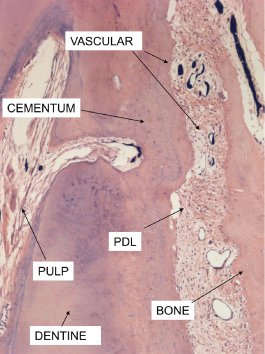
Because many reconstructive problems have a mixture of teeth and implant support (Figures 9.2–9.5), a review of the differences between osseointegrated implants and ligament-supported teeth is necessary. Teeth have a collagen-based suspension system embedded within a matrix of extracellular glycoprotein that helps dissipate forces placed on the occlusal table. In addition, the presence of a vascular supply in the ligament space indirectly provides a hydraulic cushion whereas an integrated neural component provides physiologic proprioception and reflex protection against excessive acute force (Figure 9.6).
Figure 9.2 (A) Periapical radiograph shows fractured bicuspid beneath four-unit bridge. (B) Periapical postoperative radiograph shows two implants after a sinus lift.
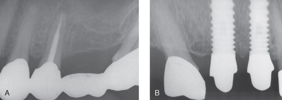
Figure 9.3 Restorative postoperative of case shown in Figure 9.2. (A) Buccal; (B) palatal
(restorative courtesy of Dr. Albert Duarte, Cambridge, MA).
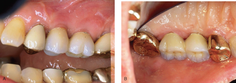
Figure 9.4 (A, B) Four implants placed in narrow ridge to replace #18–23
(restorative courtesy of Dr. Albert Duarte, Cambridge, MA).
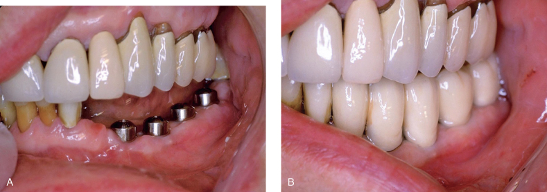
Figure 9.5 (A, B) Occlusual view of Figure 9.4.
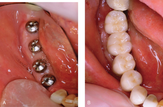
Figure 9.6 Histology near apex of tooth.
Normal functional loads on the posterior teeth in the intact dentition are compressive and well tolerated but chronic parafunctional forces can create lateral stress that overloads the periodontal support complex and may result in “physiologic adaption” in the form of mobility and migration of the teeth. Once the posterior teeth “adapt,” sometimes referred to as posterior bite collapse, the anterior teeth come under increasing protrusive loads (Figures 9.7 and 9.8). It should be noted that these adaptions protect the individual teeth, not the occlusion. Preservation of occlusal function and aesthetics requires the dental therapist to minimize these “adaptions,” otherwise the occlusion becomes disabled and functions at a less than optimal potential. The art and science of managing occlusal forces acting on an individual arch is a combination of estimating the remaining support (tooth mobility is a good proxy); controlling the location, direction, and distribution of occlusal contacts; and using mechanical load-sharing methods such as splinting or by choosing opposing restorative strength (Figure 9.9). the most vulnerable component in the biology of the natural tooth support system is the vascular net of the periodontal ligament space. The alveolar vascular supply maintains this suspension complex with a pattern of flow directed from inside the bone outward through the ligament space into the gingiva, where it interconnects with the gingival vascular complex (Figure 9.10). If this space is compromised by prolonged or repetitive compressive forces, alveolar bone and root-cemental resorption can occur (Figure 9.11) with a widening of the ligament space; this can result in mobility and migration of teeth (Figures 9.7 and 9.8). Exceeding the elastic limit of these biological materials results in permanent deformation.
Figure 9.7 Severe bite collapse with “physiologic” adaption.
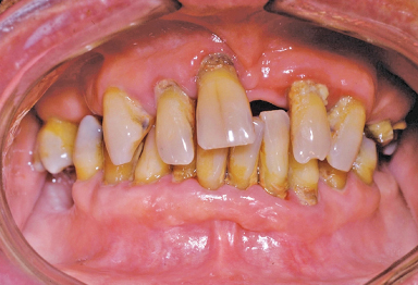
Figure 9.8 Lateral profile same patient as in Figure 9.7. Radiographs in this patient showed 50% or more bone loss, with only teeth #20, 22, 27, and 29 usable.
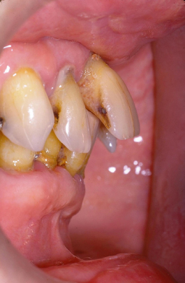
Figure 9.9 (A) Final restorative on patient in Figures 9.7 and 9.8. (B) Lingual, same patient.
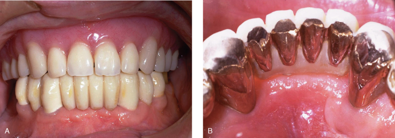
Figure 9.10 Vascular supply to dental/periodontal tissues: distribution of microcirculation and direction of flow.
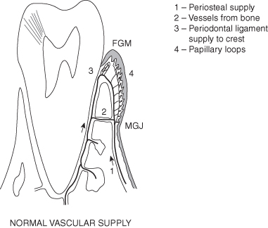
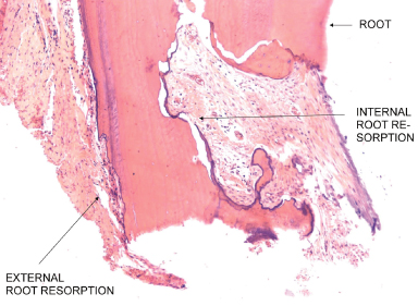
Figure 9.11 Histology-human tooth-INTERNAL and external root resorption-trauma related to occlusal loads.
From: Price A. Comparison of the Microvascular Disruption and Regeneration Following Full, Partial, and Modified Partial Thickness Pedicle Flaps in the Alveolar Mucosa of Macaca mulatta Monkeys. D.Sc.D. thesis, Boston University, 1974. p. 180.
Implants do not have a ligament, and they don’t have a known proprioceptive response. The implant surface is integrated or is in direct physical contact with the mineralized component of the bone structure (Figure 9.12). The elasticity in this construction depends on both the elastic modulus of the materials involved (Figure 9.13) and the bone, which has a varied three-dimensional architecture (Figure 9.14) and a dynamic state of mineralization. Since in clinical treatment, the details of the bone interface and the stress absorptive capacities of varied bone architectures are not available, the mechanics of the crown-abutment and abutment-implant interface become the focus of our interest for treatment planning. Testing the strength issues involved in these mechanical connections results in the same conclusions found in the analysis of the natural tooth attachment: Compressive forces are well tolerated whereas lateral forces can be destructive (Figure 9.15).
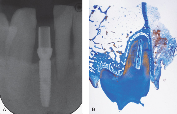
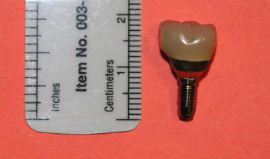
Figure 9.12 Note the integration of bone with the fractured implant. Even the increase in leverage after the bone loss at the neck of the implant could not disintegrate the lower portion. It had to be removed by trephine.
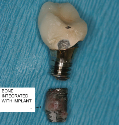
Figure 9.13 (A) Calculation modulus of elasticity. (B) Stress PSI on left. Deformation compared for different material.
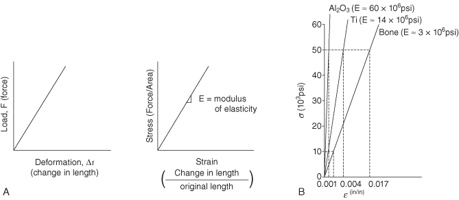
Figure 9.14 Note vascular system is perfused with India ink. “Bone density” when viewed microscopically is revealed to be a product of the relative frequency, distribution, and size of bone trabeculae. In this figure sample 1 would be judged as more dense or “hard,” and sample 4 would be sensed as less dense or “soft” when drilling an implant osteotomy.
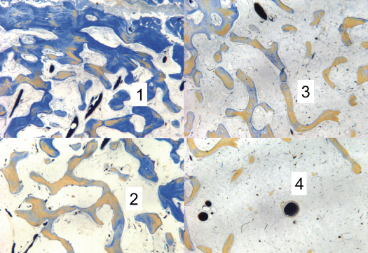
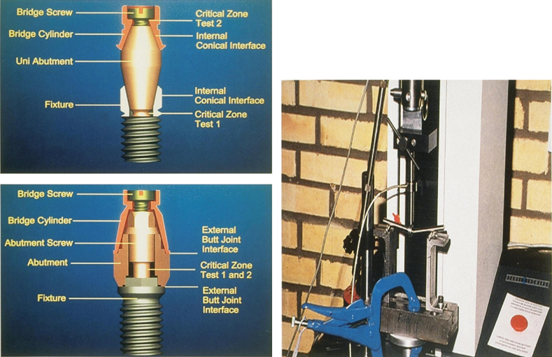
Figure 9.15 Testing deformation on internal vs. external abutment to implant attachments.
From: Norton, MR. 1997. An in vitro evaluation of the strength of an internal conical interface compared to a butt joint interface in implant design, Clinical Oral Implant Research. 8:290–98.
Once implants are integrated, forces that are compressive tend to push the implant components together and are well tolerated whereas lateral forces create mechanical stress by bending the connector parts. Where the stress becomes dissipated depends on the nature and arrangement of the parts. In two-piece implant designs such as the classic Branemark external hex platform the abutment screw is the smallest component and most vulnerable to deformation. In an internal attachment design, the weakest link is usually in the collar design (Figures 9.15 and 9.16). With either style, if the connecting interface is strengthened, the result performs more like a one-piece implant, which is the third variation in design. if the occlusal table is overloaded by lateral vectors of force, the stress is focused at the bone crest, which becomes the fulcrum of rotation. In such cases, the implant may experience crestal bone loss (Figure 9.17); the body of the implant itself may break (Figures 9.12 and 9.18); or the implant may experience bone loss and eventual complete loss of integration (Figure 9.19).
Figure 9.16 (A) Branemark external style. (B) Astra internal style.
From Norton, MR. An in vitro evaluation of the strength of an internal conical interface compared to a butt joint interface in implant design. Norton, MR. 1997. An in vitro evaluation of the strength of an internal conical interface compared to a butt joint interface in implant design, Clinical Oral Implant Research. 8:290–98.
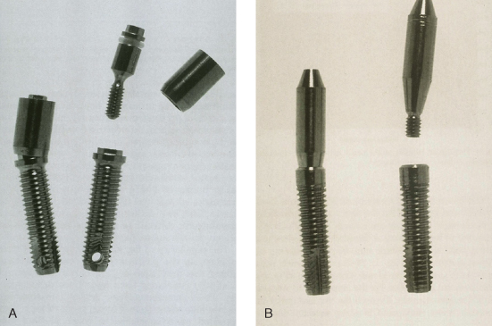
Figure 9.17 Failing implant and bone loss, which may have been an inappropriate fit of framework.
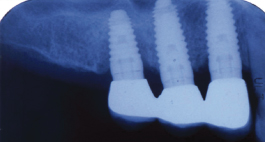
Figure 9.18 Note bone loss to dept of abutment screw and then fracture related to occlusal overload.
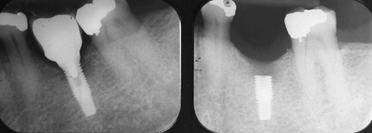
Figure 9.19 Avulse implant/crown restoration. Complete disintegration after 2 years. Note poor crown/root ratio and excessive occlusal table/implant diameter difference.
THREE-DIMENSIONAL POSITIONING IN THE ALVEOLAR HOUSING
Positioning of the implant within the alveolar housing entails different biological demands when compared to the natural tooth connections. When the buccal-lingual placement of natural teeth is visualized in the alveolous, we find that teeth are often positioned toward the plane of the buccal plate and even beyond it, with minimal bone on the buccal aspect (Figures 9.20 and 9.21). The biology of the periodontal ligament with a rich vascular supply interlinked with the gingival supply supports bone dimensions of less than 1 mm. In mesio-distal positioning of teeth, the interproximal area between two teeth has an enriched vascular net from two periodontal ligaments, which also permits closer root proximity and narrow interproximal bone. An edentulous ridge, on the other hand, is quite different and is compromised, with minimal interconnections between the bone marrow and the external gingival supply. Because of these different anatomic relationships, the vascular needs of the bone in a newly integrated implant are derived predominately from endosseous origins. Branemark’s research suggested that 3 mm was the minimum bone needed between implants in the anterior hybrid restoration. This was based on recognition that the residual vascular supply to the interimplant bone conditions after adjacent osteotomies is limited by the presence of highly compact bone with minimal internal circulation. As a general rule, the consensus suggests that an implant should have at least 1 mm of bone on the buccal and lingual and at least 2–3 mm of bone between adjacent implants. The aesthetic needs of a restoration place different demands on spacing. They may require that the implant be placed mesio-distally in the center of the tooth form, and sometimes this results in more than 3 mm between implant bodies. The final proximity can have effects on the interproximal soft tissue and the creation of “black triangles.” In addition to these aesthetic needs, a successful osseointegration requires primary stability at the time of surgery, which is best provided by engagement of cortical bone. The hunt for cortex at potential implant sites therefore becomes a primary quest in surgical treatment planning.
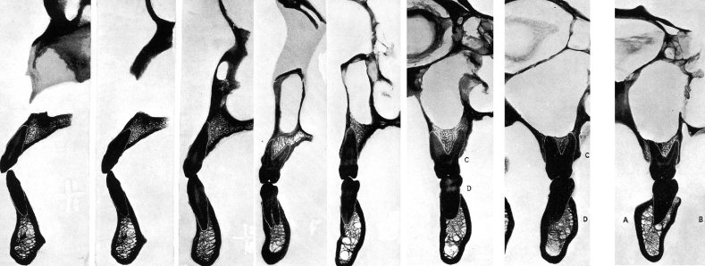
Figure 9.20 (A) Minimal bone on buccal (notch on buccal): maxillary first bicuspid. (B) Minimal bone on buccal (notch on buccal): Mandibular first bicuspid.
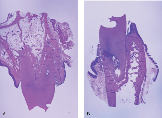
Figure 9.21 Location of teeth related to center of alveolar housing.
From: Ash, MM Jr. 1993. Wheeler’s Dental Anatomy, Physiology and Occlusion, 7th ed. Philadelphia: WB Saunders.
The preceding discussion suggests that for both implants and teeth the transfer of forces from the occlusal plane to the support structures is best tolerated if the loads are compressive in nature. To maximize this compressive loading, the placement of the implant or tooth should be oriented perpendicular to the plane of occlusion and close to the center of the occlusal table. To evaluate the available bone and guide this placement, the most useful diagnostic information would provide real-size buccal-lingual and mesial-distal cross sections of the site oriented perpendicular to the plane of occlusion. Various imaging techniques have been applied to this evaluation: periapical, panoramic radiograph, tomograph, and CT scan.
In comparison tests, the periapical radiographs, whether conventional or digital, were found to be affected by inaccuracy of up to 15% (Figure 9.22 ), whereas panoramic tomographic systems are prone to enlargement and increased distortion of 20–25% (Figure 9.23). Both mediums provide mesio-distal views, but neither of these techniques allows a bucco-lingual cross section. Sequential tomographs using selected focal planes allow an approach to our goal, but increased slice thickness often results in blurry images of poor qualit/>
Stay updated, free dental videos. Join our Telegram channel
VIDEdental - Online dental courses


