Chapter 10
Immediate Implants: Controversy or Risk Assessment?
Branemark’s (1985) original protocol for placement and loading of endosseous implants was associated with a limited experimental design: the placement of multiple implants in anterior edentulous areas with severe alveolar bone loss to support a hybrid prosthesis. Techniques soon evolved for single tooth replacement, posterior sites, grafted sites, and even immediate implant placement. Lazarra (1989) was among the first to document that an implant might be placed into a fresh extraction socket, and since then multiple reports have confirmed long-term retention of immediate implants is possible. Consideration of immediate placement presents an added challenge in the surgical decision-making process with the potential reward of a more compressed restorative time line. The treatment planning for this technique requires review of issues familiar to any endosseous implant surgery: achieving primary stability, knowledge of the rate of bone formation and remodeling, and planning for the longer term biological, biomechanical, and aesthetic stability of the final restoration.
Biological stability under ideal conditions requires at least 1 mm of vital bone on all sides of a single implant and 2–3 mm of bone between adjacent implants and/or teeth. The principal concern is to preserve adequate vascular supply to the bone. Biomechanical stability is secured by placement of the implant platform in the center of the load-bearing surface (the occlusal table) and placement of its long axis as close as possible to a 90-degree angle relative to the plane of occlusion. This minimizes lateral stress and maximizes compressive loading of the crown-abutment-implant-bone complex (Figure 10.1). Aesthetic concerns require that the implant platform be centered on and slightly smaller than the emergence profile of the tooth form to be replaced and that the platform be placed at a suitable vertical level to allow a transition from the round head of the implant to the varied profiles of the natural tooth (Branemark et al. 1985; Ash 1993; private patient files; Figures 10.1, 10.2; see also 10.44)
Figure 10.1 Implant placed at right angle to occlusal plane. Appropriately sized.
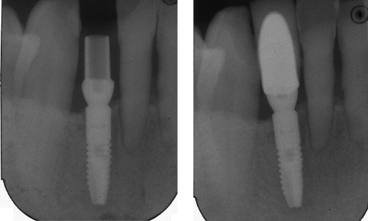
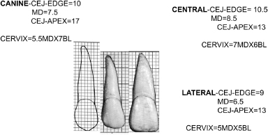
Figure 10.2 Mean measures of tooth dimension.
Abstracted from Ash, MM Jr. 1993. Wheeler’s Dental Anatomy, Physiology and Occlusion, 7th ed. Philadelphia: WB Saunders.
Immediate and long-term biomechanical stabilization in edentulous sites requires maximum engagement of the available mineralized component of the bone at a specific site. The bone present at that site should be vital or should have the capacity to convert to vitality because osseointegration depends on interaction with live bone. Because the mineralized microarchitecture (cortical bone and trabecular arrangement) varies with each location, a continuous tactile feedback sensitivity is necessary at the time of surgery to maximize the bone’s contribution to this stability (see also Chapter 9 in this text). Socket sites are defined by different microarchitecture parameters from that of the mature edentulous site, with the socket offering little stability and available cortical bone often limited to the apical one-third of the site. It is imperative to be conversant with individual site variation and to separate consideration of single-rooted teeth from multirooted teeth. (Wheeler’s text (1993) is an excellent source for reviewing root dimensions and therefore visualization of the socket dimension) (see Figures 10.2–10.8).
Figure 10.3 Location of roots relative to alveolar housing.
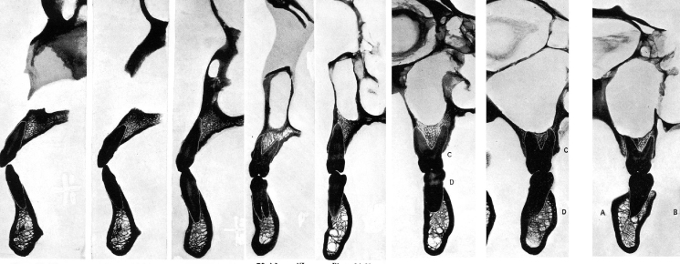
Figure 10.4 Tooth position and angulation within alveolar bone. Note: The root position buccal results in thin buccal bone. Arrows denote midline of alveolous.
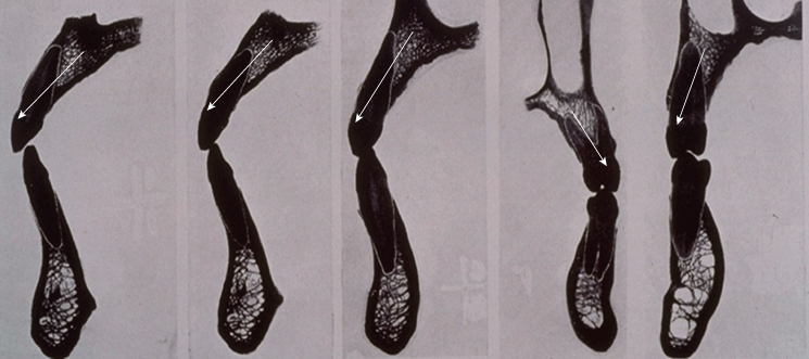
Figure 10.5 Mandibular incisors-sockets.
From Ash, MM Jr. 1993. Wheeler’s Dental Anatomy, Physiology and Occlusion, 7th ed. Philadelphia: WB Saunders.
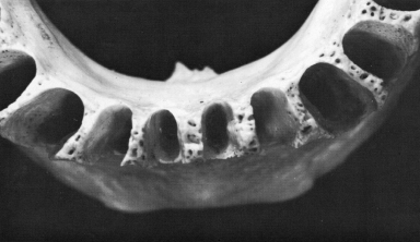
Figure 10.6 Composite of mean measures of human teeth.
Adapted from Ash, MM Jr. 1993. Wheeler’s Dental Anatomy, Physiology and Occlusion, 7th ed. Philadelphia: WB Saunders.
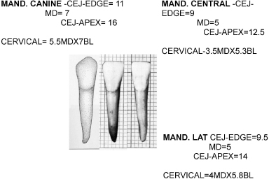
Figure 10.7 Sockets mandibular bicuspids/molars.
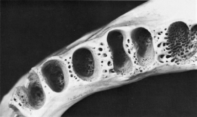
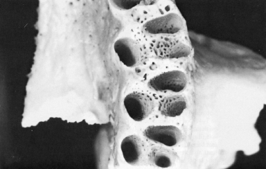
Figure 10.8 Sockets maxillary molars.
Bone formation rates in socket-healing studies suggest that a minimum of 3–4 months are required before new trabeculae are mineralized enough to support minimal loads and that a 6-month wait is necessary before bone is sufficiently mineralized to withstand full functional loading. (See variation in grafted versus ungrafted sites in Figures 10.9 and 10.10; private patient files).
Figure 10.9 97-3-2 (6-month extraction site—no graft) Note the premolar site—thinner trabeculae alternate with a mixed fibrous-fatty marrow.
(From Price and Van Dyke 2003).
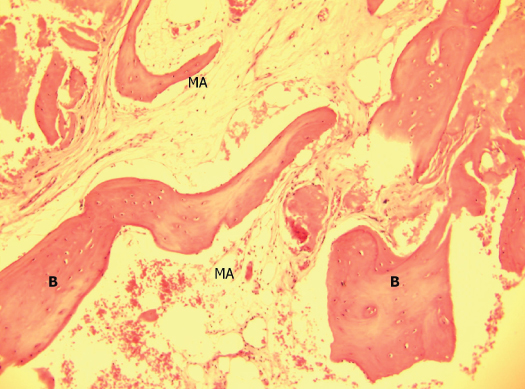
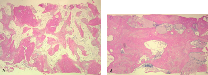
Figure 10.10 (A) #14 socket graft: Decalcified freeze-dried bone allograft (DFDBA): 5 months. (B) #5 socket graft: PUROS: 6 months.
(From Histology and Cores: Caterina Venuleo, 2007.)
SOCKET SITE ANATOMY
In the maxillary anterior, the socket profile is often a single-rooted tooth placed near the buccal plate with the socket-tooth profile often penetrating the buccal of the alveolar profile (Ash 1993). This natural tooth location often results in a “washboard” effect to palpation of the buccal anatomy (Figure 10.14). The facial bone is stretched thin over the roots, and it is not uncommon to find less than 0.5 mm of bone on the buccal wall of the residual socket (Ash 1993; private patient files; Figures 10.3, 10.4, 10.11–10.13). Because the implant’s biological need requires at least 1 mm of bone over the buccal surface, this requires positioning the osteotomy closer to the center of the alveolar profile. In addition, the lateral incisor site has an apical depression on the buccal (private patient files; Figures 10.14, 10.15). Given the average socket depth of 8–13 mm for incisors and bicuspids (15–16 mm for the cuspid) and the void presented by the socket, it is necessary to place the osteotomy against and into the palatal aspect of the socket and use a 13- to 16-mm implant to gain anchorage. This requires placement at a more protrusive angle. In the maxillary arch from central incisor to second bicuspid, the projection of the geometric center of the alveolar profile tends to parallel the palatal slope and is projected at the buccal cervical line of the natural tooth crown (private patient files; Figure 10.12). The placement of the maxillary lateral incisor requires an even more acute angle due to the incisal fossa. To compensate for the potential of buccal exposure of the “knee” presented by the subsequent abutment-implant interface, the implant needs to be driven further subcrestally and apically. The first bicuspids in the maxillary arch often have thin buccal plates and a bifurcated root (Ash 1993; private patient files; Figures 10.3, 10.4, 10.11A,
Stay updated, free dental videos. Join our Telegram channel
VIDEdental - Online dental courses


