CHAPTER 8 Indirect Retainers
Role of Indirect Retainers in Control of Prosthesis Movement
As was described in Chapter 4, partial denture movement can exist in three planes. Tooth-supported partial dentures effectively use teeth to control movement away from the tissues. Tooth-tissue–supported partial dentures do not have this capability because one end of the prosthesis is free to move away from the tissue. This may occur because of the effects of gravity in the maxillary arch or adhesive foods in either arch. Attention to the details of design and location of partial denture component parts in control of functional movement is the strategy used in partial denture design.
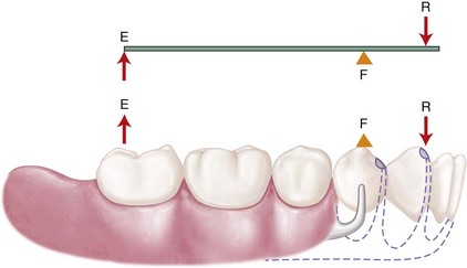
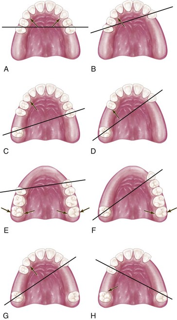
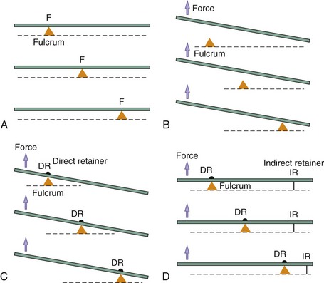
When the distal extension denture base is dislodged from its basal seat, it tends to rotate around the fulcrum lines. Theoretically, this movement away from the tissues can be resisted by activation of the direct retainer, the stabilizing components of the clasp assembly, and the rigid components of the partial denture framework, which are located on definite rests on the opposite side of the fulcrum line away from the distal extension base. These components are referred to as indirect retainers (Figures 8-1 and 8-2). Indirect retainer components should be placed as far as possible from the distal extension base, which provides the best leverage advantage against dislodgment (Figure 8-3).

Figure 8-1 Mandibular distal extension removable partial denture showing the distal extension base being lifted from the ridge and the clasp assembly being activated and engaged, with the indirect retainer providing stabilization against dislodgment.

Figure 8-2 Fulcrum lines found in various types of partially edentulous arches, around which the denture may rotate when bases are subjected to forces directed toward or away from the residual ridge. Arrows indicate the most advantageous position of indirect retainer(s). A-B, In a Class I arch, the fulcrum line passes through the most posterior abutments, provided some rigid component of the framework is occlusal to the abutment’s heights of contour. C, In a Class II arch, the fulcrum line is diagonal, passing through the abutment on the distal extension side and the most posterior abutment on the opposite side. D, If the abutment tooth anterior to the modification space lies far enough removed from the fulcrum line, it may be used effectively for support of the indirect retainer. E-F, In a Class IV arch, the fulcrum line passes through two abutments adjacent to the single edentulous space. G, In a Class III arch with a posterior tooth on the right side, which has a poor prognosis and eventually will be lost, the fulcrum line is considered the same as though posterior tooth were not present. Thus its future loss may not necessitate altering the original design of the removable partial denture framework. H, In a Class III arch with nonsupporting anterior teeth, the adjacent edentulous area is considered to be the tissue-supported end, with a diagonal fulcrum line passing through the two principal abutments, as in a Class II arch.

Figure 8-3 Indirect retainer principle. A, Beams are supported at various points. B, A lifting force will displace the entire beam in the absence of retainers. C, With direct retainers (dr) at the fulcrum, the lifting force will depress one end of the beam and elevate the other end. D, With both direct and indirect retainers (ir) functioning, the lifting force will not displace beam. The farther the indirect retainer is from the fulcrum, the more efficiently it should control movement.
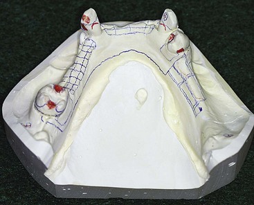
An indirect retainer consists of one or more rests and the supporting minor connectors (Figures 8-4 and 8-5). The proximal plates, adjacent to the edentulous areas, also provide indirect retention. Although it is customary to identify the entire assembly as the indirect retainer, it should be remembered that the rest is actually the indirect retainer united to the major connector by a minor connector. This is noted to avoid interpretation of any contact with tooth inclines as part of the indirect retainer. An indirect retainer should be placed as far from the distal extension base as possible in a prepared rest seat on a tooth capable of supporting its function.

Figure 8-4 Planning the location for an indirect retainer for a Class II modification 2 removable partial denture. The greatest distance from the axis of rotation around most distal rests (fulcrum line) would fall on #22. The decision to use an incisal rest or cingulum rest will depend on the patient’s concern for the esthetic impact of an incisal rest versus having a crown (for the cingulum rest).

Figure 8-5 Example of indirect retention used in conjunction with a palatal plate–type major connector. Indirect retainers are proximal plates on second premolars and occlusal rests located on first premolars. A secondary function of auxiliary occlusal rest assemblies is to prevent settling of the anterior portion of the major connector and to provide stabilization against horizontal rotation.

Stay updated, free dental videos. Join our Telegram channel

VIDEdental - Online dental courses

