Radiographic Imaging in Implant Dentistry
Randolph R. Resnik, Carl E. Misch
The use of diagnostic imaging in implant dentistry has changed tremendously over the years. Comprehensive and accurate radiographic assessment is a crucial aspect of dental implant treatment planning. Various imaging techniques have been used to evaluate bone quality, quantity, and anatomic structures in relation to the proposed implant sites. Traditionally, implant clinicians have relied on two-dimensional conventional radiograph modalities in implant dentistry. However, with the advent of computed tomography (CT), a new era in all phases of the radiographic imaging survey of implant patients has become available. These technological advances have significantly increased the level of detailed information available to implant clinicians in the diagnosis, treatment planning, surgical, and prosthetic phases of dental implant treatment. This chapter reviews the various radiographic technologies and their diagnostic contributions specific to implant dentistry relative to presurgical evaluation, treatment planning, and postoperative assessment.
Classification of Radiographic Imaging Techniques
The goal of radiographic imaging in implant dentistry is to acquire the most practical and comprehensive information that can be used for the various phases of implant treatment. The implant team must assess each individual patient on which imaging modality should be used, and the decision should be based on sound and practical information.
Phase 1
Phase 1 is termed presurgical implant imaging and involves all past radiologic examinations and new radiologic surveys chosen to assist the implant team in determining the patient’s final comprehensive treatment plan. The objectives of this phase of imaging include all necessary surgical and prosthetic information to determine the quantity and quality of bone, identification of vital structures, prosthetic needs, proposed implant sites, and the presence or absence of disease.
Phase 2
Phase 2 is termed the surgical and intraoperative implant imaging phase and is focused on assisting in the surgical and prosthetic intervention of the patient. The objectives of this phase of imaging are to evaluate the surgery sites during and immediately after surgery, assist in the ideal position and orientation of dental implants, evaluate the healing and integration phase of implant surgery, and ensure that abutment position and final prosthesis fabrication are correct.
Phase 3
Phase 3 is termed the postprosthetic implant imaging. This phase commences just after the prosthesis placement and continues indefinitely. The objectives of this phase of imaging are to access the long-term maintenance, integration, and function of the implants, which includes the evaluation of the implant complex and surrounding crestal bone levels.
Imaging Modalities
The decision to image the patient is based on the patient’s clinical needs. To obtain a radiologic survey of a particular area of interest, the imaging modality is selected that yields the necessary diagnostic information related to the patient’s surgical and prosthetic needs. Maximizing the ratio of benefit to risk for acquiring information from imaging examinations is a fundamental tenet of radiology. Examinations known to produce this result are not necessarily the examinations that cost the least, are in proximity to the dentist, or produce the lowest radiation exposure.1–3 However, they enable the implant team to acquire necessary information that is crucial to the success of the implant procedures.
Many imaging modalities have been reported in the literature as useful for dental implant imaging, including devices recently developed specifically for dental implant imaging (Box 7-1).4,5 These imaging modalities can be classified as analog or digital and either two or three dimensional. In the past, radiographic imaging was limited to analog two-dimensional imaging. Analog imaging modalities are two-dimensional systems that use radiographic film or intensifying screens as the image receptors. However, the image quality of these systems is plagued by many disadvantages such as resolution quality, limited field of view (FOV), time consuming, excessive radiation exposure, and being highly dependent on operator characteristics.6–8
In the past, intraoral radiographs along with panoramic images were used as the sole determinants of implant diagnosis and treatment planning. Two-dimensional imaging techniques in the field of dentistry have inherent disadvantages and have been shown to exhibit high false-negative and false-positive images.9–11 With the advancement of radiographic technology, various three-dimensional imaging systems are now available to the dental profession, allowing implant teams an infinite amount of diagnostic information.
Presurgical and Diagnostic Imaging (Phase 1)
The goal of presurgical radiographic evaluation is to assess the available bone quality and quantity, angulation of bone, and selection of potential implant sites and to verify the absence of pathology. However, there exists no ideal two-dimensional radiographic imaging technique in the field of oral implantology that would be acceptable for all patients. When selecting a radiographic modality for preoperative assessment, a careful examination of the available imaging options should be evaluated for selection as per the patient’s needs. In dental and medical radiology, a recommended principle when selecting the appropriate radiographic modality is based on radiation dosage. The “as low as reasonably achievable” (ALARA) principle should always be adhered to, which states that the diagnostic imaging technique selected should include the lowest possible radiation dose to the patient. However, patient care and treatment planning should not be jeopardized in response to radiation dose. Advances in technology that permit reduced radiation doses to obtain a similar radiographic image over recent years have dramatically reduced this concern.
All of the modalities identified in Box 7-1 have been shown in the literature to have been used in the first diagnostic phase of treatment.4,5 However, the radiographic modality selected should allow for presurgical implant treatment planning with high-resolution and dimensionally accurate three-dimensional information about the patient at the proposed implant sites.
The imaging modalities listed in Box 7-1 can be subdivided into planar two-dimensional and three-dimensional imaging modalities. Planar imaging modalities include periapical, bitewing, occlusal, and cephalometric imaging and are simply two-dimensional projections of the patient’s anatomy. Three-dimensional imaging techniques include CT, cone-beam computed tomography (CBCT), and magnetic resonance imaging (MRI), which enable the dentist to view a volume of the patient’s anatomy. These techniques are quantitatively accurate, and three-dimensional models of the patient’s anatomy can be derived from the image data and used to produce stereolithographic surgical guides and prosthetic frameworks.
This phase of implant imaging is intended to evaluate the current status of the patient’s teeth and jaws and to develop and refine the patient’s treatment plan. Evaluation of the patient by members of the dental implant team is accomplished with a review of the patient’s history, a thorough clinical examination, and evaluation of the patient’s radiologic examinations. The dental implant team should be able to rule out any existing pathology and establish a tentative clinical objective that meets the patient’s functional and esthetic needs.
The objective of this phase of treatment is to develop and implement a treatment plan for the patient that allows for the restoration of the patient’s function and esthetics by the accurate and strategic placement of dental implants. The patient’s functional and esthetic needs can be transformed physically into a three-dimensional diagnostic template, which enables the implant team to identify the specific sites of prospective implant surgery in the imaging examinations. The specific objectives of preprosthetic imaging are listed in Box 7-2.
Periapical Radiography
Technique
Periapical radiographs are high-resolution images of a limited region of the mandibular or maxillary alveolus.12 There exist two intraoral projection techniques that may be used in periapical radiology: the paralleling and bisecting the angle techniques. Although both methods are used in dentistry today, the paralleling technique is generally preferred in implant dentistry because of less distortion and magnification. The paralleling technique necessitates placing the film or sensor parallel in relation to the long axis of the implant, tooth, or osseous structure in question. Additionally, the central ray of the x-ray beam is directed perpendicular to the film or sensor. When used in oral implantology, this technique reduces geometric distortion and magnification. If the bisecting the angle or poor technique is used in obtaining images, the resultant images will have inaccurate vertical and horizontal measurements.13 The paralleling technique eliminates distortion and usually limits magnification to less than 10%. On occasion, the bisecting the angle technique is necessary to observe the apical region of bone or the implant because of the anatomy of the surrounding region.
One of the most significant recent advances in dental radiology is the advent of digital technology, which has allowed reduction of numerous limitations of conventional intraoral radiography. The advantages of digital radiography and the uses in oral implantology are well documented14,15 (Table 7-1). With the use of digital radiography, implant surgical procedures and prosthetics have been simplified with increased efficiency.
TABLE 7-1
Comparison of Film versus Digital-Based Images
| Film | Digital | |
| Image | Analog | Analog ~ digital |
| Cost | Film, chemicals | Up front |
| Radiation | High | 50%–90% less |
| Viewing | Delayed | Immediate |
| Resolution | 14–18 Ln/mm | 12–20 Ln/mm |
| Gray scale | 16 shades | 256 shades |
| Film | Thin, flexible | Thin, cord |
| Enhancement | Unchangeable | Wide range |
| Storage | Chart | Computer |
Data from Park ET, Williamson GF: Digital radiography: an overview, J Contemp Dent Pract 3:1–13, 2002.
Digital radiology is an imaging process wherein the film is replaced by a sensor that collects the data. The analog information received is then interpreted by specialized software, and an image is formulated on a computer monitor. The resultant image can be modified in various ways, such as gray scale, brightness, contrast, and inversion. Color images may be formed to enhance the digital image for better evaluation. Computerized software programs (i.e., Dexis Implant) are now available that allow for calibration of magnified images, thus ensuring accurate measurements (Figure 7-1).
Compared with conventional radiographs, the most current digital systems have significantly less radiation16,17 with superior resolution.15 However, with respect to oral implantology, the most significant advantage of digital radiography is the instantaneous speed in which images are formed, which is highly useful during surgical placement of implants and the prosthetic verification of component placement.
Advantages
Periapical radiology is an excellent radiologic modality that has many advantages over other radiographic techniques in implant dentistry. This type of radiography exhibits a very low radiation dose, especially if the images are obtained digitally. The resultant images have high resolution and can be modified in various ways, such as the gray scale, brightness, contrast, and inversion. Color images may be formed for enhancement of evaluation and density readings. Most computer software programs are now available to allow for calibration of magnified images, thus ensuring accurate measurements.
Disadvantages
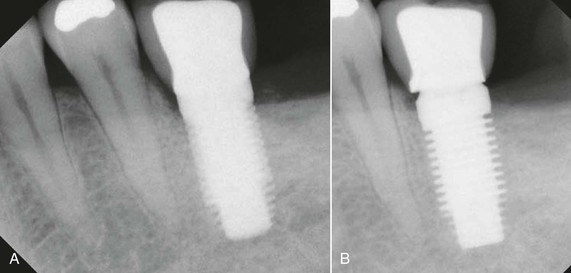
Periapical radiology does have inherent disadvantages. Because the cortical plates in the mandible are thick, the mandibular canal and bone density are difficult to access. Image shape distortion and magnification may be present when unequal magnification of the object exists. This occurs when the total area in question (e.g., alveolar bone, implant) does not have the same focal spot-to-object distance. When the x-ray beam is perpendicular to the object but the object is not parallel to the film, foreshortening will occur. If the x-ray beam is oriented perpendicular to the object but not the film, elongation will occur. These basic and important concepts help to minimize distortion and magnification when using intraoral radiographs18 (Figure 7-2).
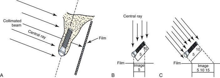
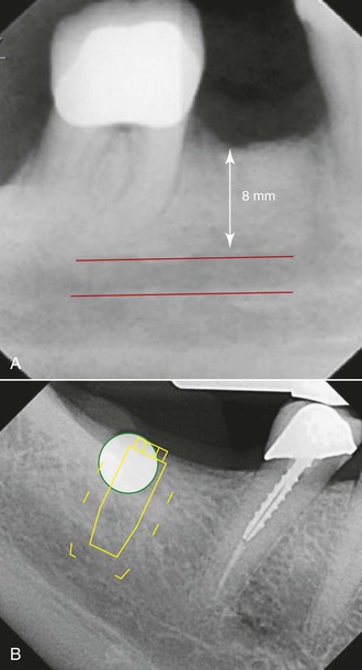
Image magnification may be assessed by placing a known-dimension radiographic marker (e.g., 5-mm ball bearing) at the crestal region of the desired implant location. When the marker is elongated, so is the implant site. For example, a ball bearing radiographic measurement of 8 mm relates to a 62% magnification (5 mm/8 mm = 62%). Therefore, the image below the ball bearing may represent a 60% magnification of dimension. Most digital radiographic systems have built-in magnification programs that allow for the determination of this distortion (Figure 7-3).
The most significant disadvantage of periapical radiology leading to image distortion is difficulty in film positioning. In certain situations, the opposing landmark of available bone in implant dentistry is beyond the lingual muscle attachments in the mandible or beyond the palatal vault in the maxilla. As such, the image most often must be foreshortened to visualize the opposing cortical plate, and the actual available bone height may be difficult to determine.
The bone density at the crest is also a factor to evaluate crestal bone loss with radiographic indexes. In D4 bone, no cortical plate is present on the crest, and fine trabecular bone is primarily present. Burnout effects are common when standard kilovolt (kVp) and milliampere (mA) settings are used, making crestal bone loss evaluation with digital intraoral systems of benefit in these situations19,20 (Box 7-3).
Phase 1 and Phase 2
Periapical imaging is often used in phase 1 and 2 treatment. The evaluation of small edentulous spaces, alignment and orientation of the implant during surgery, and confirmation that the implant is not invading an adjacent tooth root or mandibular canal during surgery are major benefits of periapical images. Ideally, a digital periapical radiograph should be taken immediately after surgery when possible. This image type can be used as a baseline to evaluate bone levels and healing.
Abutment and Prosthetic Component Imaging
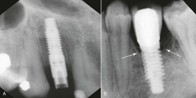
When evaluating for transfer impressions along with two-piece abutment component placement, radiographs should be taken to verify complete seating. Intraoral radiographs should be used because of their high geometric resolution to evaluate for any fit discrepancy. However, care must be taken so that the x-ray beam is directed at a right angle to the longitudinal axis of the implant. Even a slight angulation may allow a slight gap to remain unnoticed. When positioning is difficult for periapical radiographs, bitewing or panoramic radiographs may be used (Figures 7-4 and 7-5).
Postprosthetic Imaging (Phase 3 Treatment)
A postprosthetic radiograph ideally needs to be taken to act as a baseline for future evaluation of component fit verification and for marginal bone level evaluation. Care must be taken to ensure that adequate fit of all components is made. In addition, the marginal bone level must be determined for future evaluation. Additionally, the postprosthetic image may be used to verify the absence of cement, which may lead to tissue irritation, bone loss, and infection.
Recall and Maintenance Imaging
For the evaluation of implant success, immobility and radiographic evidence of bone adjacent to the implant body are the two most accurate diagnostic aids in evaluating success. Follow-up or recall radiographs should be taken after 1 year of functional loading and yearly for the first 3 years.21 Multiple studies have shown that in the first year, marginal bone loss and a higher rate of failure are seen.
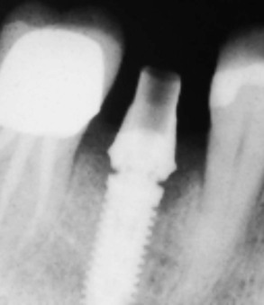
Radiographically, lack or loss of integration is usually indicated as a radiolucent line around the implant. However, false-negative diagnoses may be made when the soft tissue surrounding an implant is not wide enough to overcome the resolution of the radiographic modality. False-positive diagnoses may also be made when a “Mach band effect” results from an area of lower radiographic density adjacent to an area of high density (implant), which results in a more radiolucent area than is actually present.22 However, studies have shown that the possibility of the Mach band effect is significantly reduced with digital image processing. Additionally, digital radiography has been shown to have an advantage over conventional radiography with respect to “edge enhancement,” which is the ability to detect space between the implant and the surrounding bone (Figure 7-6).23 Because of the variability of operator-controlled problems, a strict quality assurance protocol should be used to maintain ideal image quality over time. Proper positioning along with documentation of kVp and mA settings should be documented for future reference.
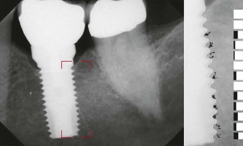
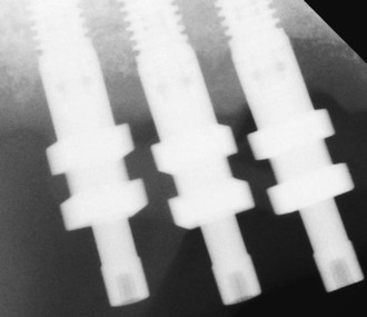
In recall radiographic examinations, the marginal bone level is compared with the immediate postprosthetic radiographs. Therefore, radiographs similar in geometry, density, and contrast are paramount. To ensure accuracy, standardized periapical radiographs are essential; however, reproduction of positioning is very difficult.24 Numerous film-holding devices have been documented that attach to the implant, abutment, or prosthesis to standardize image geometry.25–28 When proper projections are achieved, implant threads on both sides of the implant are clearly seen. If the threads are not clearly seen in the radiographs, modification of the beam angle needs to be made. If diffuse threads are present on the right side of the implant, then the beam angle was positioned too much in the superior direction. If the threads are diffuse on the left side, then the beam angle was from an inferior angulation (Figure 7-7). With digital enhanced radiographs, numerous techniques have been postulated to measure bone levels around implants. Computer-assisted measurements, rulers, calipers, and suprabony thread evaluation have been shown to have highly reproducible results.29,30
In summary, periapical radiology:
Occlusal Radiography
Occlusal radiographs are planar radiographs produced by placing the film intraorally parallel to the occlusal plane with the central x-ray beam perpendicular to the film for the mandibular image and oblique (usually 45 degrees) to the film for the maxillary image. Occlusal radiography produces high-resolution planar images of the body of the mandible or the maxilla.12 Maxillary occlusal radiographs are inherently oblique and so distorted that they are of no quantitative use for implant dentistry for determining the geometry or the degree of mineralization of the implant site. In addition, critical structures such as the maxillary sinus, nasal cavity, and nasal palatine canal are demonstrated, but the spatial relationship to the implant site generally is lost with this projection (Box 7-4).
Because the mandibular occlusal radiograph is an orthogonal projection, it is a less distorted projection than the maxillary occlusal radiograph. However, the mandibular alveolus generally flares anteriorly and demonstrates a lingual inclination posteriorly, producing an oblique and distorted image of the mandibular alveolus, which is of little use in implant dentistry. In addition, the mandibular occlusal radiograph shows the widest width of bone (i.e., the symphysis) versus the width at the crest, which is where diagnostic information is needed most (Figure 7-9). The degree of mineralization of trabecular bone is not determined from this projection, and the spatial relationship between critical structures, such as the mandibular canal and the mental foramen, and the proposed implant site is lost with this projection. As a result, occlusal radiographs rarely are indicated for diagnostic presurgical phases in implant dentistry.
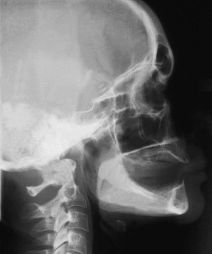
Cephalometric Radiography
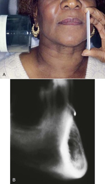
Cephalometric radiographs are oriented planar radiographs of the skull. The skull is oriented to the x-ray device and the image receptor using a cephalometer, which physically fixes the position of the skull with projections into the external auditory canal. The geometry of cephalometric imaging devices results in a 10% magnification of the image with a 60-inch focal object and a 6-inch object-to-film distance.12
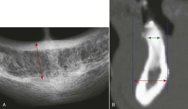
A lateral cephalometric radiograph is produced with the patient’s midsagittal plane oriented parallel to the image receptor. This radiograph demonstrates a cross-sectional image of the alveolus of the mandible and the maxilla in the midsagittal plane.19 With a slight rotation of the cephalometer, a cross-sectional image of the mandible or maxilla can be demonstrated in the lateral incisor or in the canine regions. Unlike panoramic or periapical images, the cross-sectional view of the alveolus demonstrates the spatial relationship between occlusion and esthetics with the length, width, angulation, and geometry of the alveolus and is more accurate for bone quantity determinations. Implants often must be positioned in the anterior regions adjacent to the lingual plate.
The lateral cephalometric radiograph is useful because it demonstrates the geometry of the alveolus in the midanterior region and the relationship of the lingual plate to the patient’s skeletal anatomy (Figures 7-10 and 7-11) The width of bone in the symphysis region and the relationship between the buccal cortex and the roots of the anterior teeth also may be determined before this bone is harvested for ridge augmentation. Together with regional periapical radiographs, quantitative spatial information is available to demonstrate the geometry of the implant site and the spatial relationship between the implant site and critical structures such as the floor of the nasal cavity, the anterior recess of the maxillary sinus, and the nasal palatine canal. The lateral cephalometric view also can help evaluate a loss of vertical dimension, skeletal arch relationship, anterior crown-to-implant ratio, soft tissue profile, anterior tooth position in the prosthesis, and resultant moment of forces. As a result, cephalometric radiographs are a useful tool for the development of an implant treatment plan, especially for completely edentulous patients. However, this technique is not useful for demonstrating bone quality and only demonstrates a cross-sectional image of the alveolus where the central rays of the x-ray device are tangent to the alveolus.
Disadvantages of cephalometric radiographs include cross-sectional information limited to the midline area and difficulty in cephalometric machine accessibility. Any nonmidline structure is superimposed on the contralateral side. This radiographic technique is operator technique sensitive and, if improperly positioned, will result in a distorted view. Because lateral cephalometric radiographs use intensifying screens, resolution and sharpness are compromised compared with intraoral radiographic techniques (Box 7-5).
Panoramic Radiography
Panoramic radiography is a curved plane tomographic radiographic technique used to depict the body of the mandible, maxilla, and maxillary sinuses. In the past, this modality was probably the most used diagnostic modality in implant dentistry. However, for quantitative presurgical implant imaging, panoramic radiography is not the most diagnostic. This radiographic technique produces an image of a section of the jaws of variable thickness and magnification. The image receptor traditionally has been radiograph film but may be a digital storage phosphor plate or a digital charge–coupled device receptor.20,31,32 Nonetheless, panoramic images offer many advantages (Box 7-6).
The significant limitations of panoramic radiographs can be classified into two categories: (1) distortions inherent in the panoramic system and (2) errors in patient positioning. Panoramic radiography is characterized by a single image of the jaws that demonstrates vertical and horizontal magnification along with a tomographic section thickness that varies according to the anatomical position. The x-ray source exposes the jaws from a negative angulation (8%–9%), which produces inherent magnification. The horizontal magnification is nonuniform and cannot be accurately determined because of varying positions of the patient and the focal spot–object distance and the relative location of the rotation center of the x-ray system. Clinical studies have shown that nonuniform magnification may be present in the range of 15% to 220%.33–35 Structures of the jaws become magnified more as the object-to-film distance increases and the object–x-ray source distance decreases. Structures that are located obliquely in relation to the implant receptor produce aspects of the structures that are magnified more when they are farther from the image receptor and less when they are closer to the image receptor.36–38 Uniform magnification of structures produces images with distortion that cannot be compensated for in treatment planning. The posterior maxillary regions are generally the least distorted regions of a panoramic radiograph. The tomographic section thickness of panoramic radiography or trough of focus is thick (≈20 mm) in the posterior regions and thin (6 mm) in the anterior region.38
Traditional panoramic radiography is a high-yield technique for demonstrating dental and bone disease. However, panoramic radiography does not demonstrate bone quality or mineralization and is misleading quantitatively because of magnification. Because the third-dimension cross-sectional view is not demonstrated, the relationship between the vital structures and dimensional quantitation of the implant site is not easily depicted.
Panoramic radiography is a popular and widely available technique in dentistry, and as such, dentists have developed means to compensate for its shortcomings. Implant companies often market magnified overlays with a preset 25% magnification for evaluation of an implant size that are placed on a panoramic film for comparison with vital structure positions. However, these should not be used as the only presurgical assessment of dental implant treatment planning. Because of the inherent disadvantages of panoramic radiographs, most clinical studies substantiate the inaccuracies of direct measurements.39,40
Patient positioning is also a determining factor in the inaccuracies of panoramic radiographs that lead to geometric distortion. With knowledge, most errors in patient positioning can be corrected (Table 7-2). However, in a given plane, horizontal distortion cannot be determined, and measurements are completely unreliable. The horizontal dimensions are affected by the rotation center of the beam that changes with relation to the object-to-film distance16(Figure 7-12).
Stay updated, free dental videos. Join our Telegram channel
VIDEdental - Online dental courses


