CHAPTER 7 Direct Retainers
Direct Retainer’s Role in Control of Prosthesis Movement
Retention of a removable prosthesis is a unique concern when compared with other prostheses. When one is dealing with a crown or fixed partial denture, the combined use of preparation geometry (i.e., resistance and retention form) and a luting agent can fix the prosthesis to the tooth in a manner that resists all forces to which the teeth are subjected. As was mentioned in Chapter 4, the direction of forces can be toward, across, or away from the tissue. In general, the forces acting to move prostheses toward and across the supporting teeth and/or tissue are the greatest in intensity. This is because most often they are forces of occlusion.
Basic Principles of Clasp Design
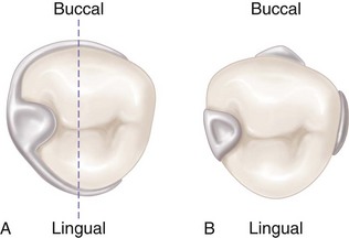
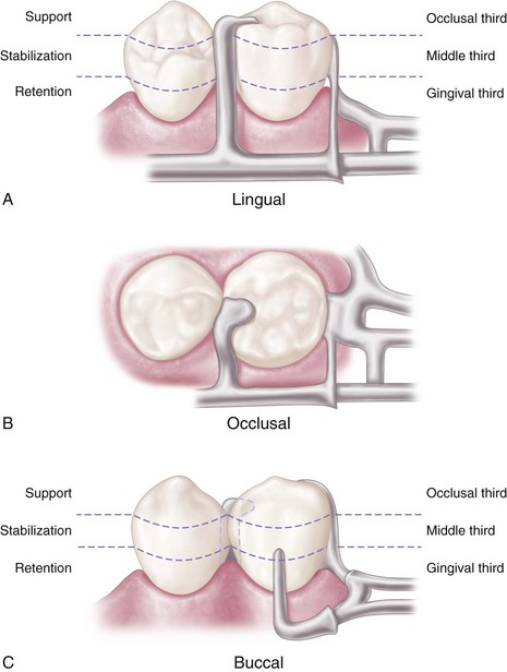
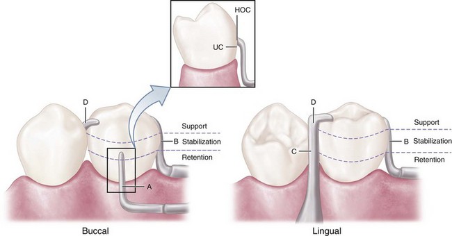
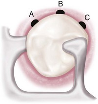
Therefore the basic principle of clasp design, referred to as the principle of encirclement, means that more than 180 degrees in the greatest circumference of the tooth, passing from diverging axial surfaces to converging axial surfaces, must be engaged by the clasp assembly (Figure 7-1). The engagement can occur in the form of continuous contact, such as in a circumferential clasp, or discontinuous contact, such as in the use of a bar clasp. Both provide tooth contact in at least three areas encircling the tooth: the occlusal rest area, the retentive clasp terminal area, and the reciprocal clasp terminal area.
In addition to encirclement, other basic principles of clasp design are as follows:
Reciprocal Arm Functions
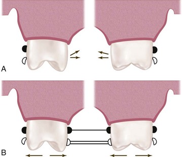
As was mentioned earlier, reciprocal arms are intended to resist tooth movement in response to deformation of the retainer arm as it engages a tooth height of contour. The opposing clasp arm reciprocates the effect of this deformation as it prevents tooth movement. For this to occur, the reciprocal arm must be in contact during the time of retainer arm deformation. Unless the abutment tooth has been specifically contoured, the reciprocal clasp arm will not come into contact with the tooth until the denture is fully seated and the retentive clasp arm has again become passive. When this happens, a momentary tipping force is applied to the abutment teeth during each placement and removal. This may not be a damaging force—because it is transient—so long as the force does not exceed the normal elasticity of the periodontal attachments. True reciprocation during placement and removal is possible only through the use of crown surfaces made parallel to the path of placement. The use of cast restorations permits the parallel surfaces to be contacted by the reciprocal arm in such a manner that true reciprocation is made possible. This is discussed in Chapter 14.
The reciprocal clasp arm also may act to a minor degree as an indirect retainer. This is true only when it rests on a suprabulge surface of an abutment tooth lying anterior to the fulcrum line (see Figure 8-8). Lifting of a distal extension base away from the tissue is thus resisted by a rigid arm, which is not easily displaced cervically. The effectiveness of such an indirect retainer is limited by its proximity to the fulcrum line, which gives it a relatively poor leverage advantage, and by the fact that slippage along tooth inclines is always possible. The latter may be prevented by the use of a ledge on a cast restoration; however, enamel surfaces are not ordinarily so prepared.
Types of Direct Retainers
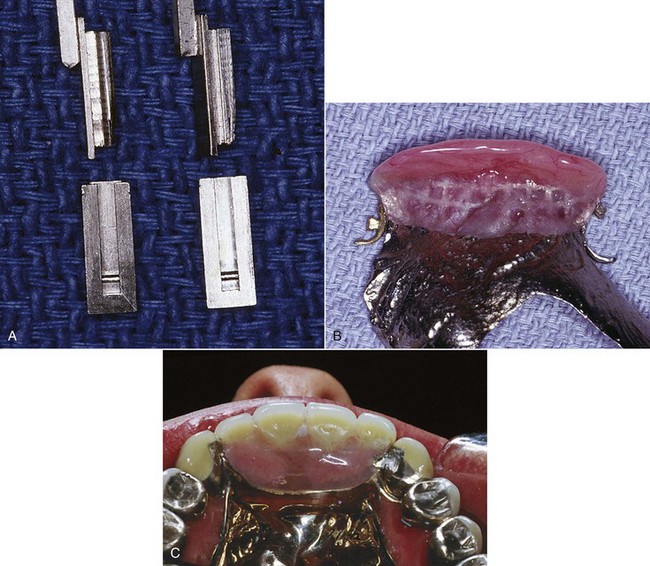
The intracoronal retainer may be cast or may be attached totally within the restored natural contours of an abutment tooth. It is typically composed of a prefabricated machined key and keyway with opposing vertical parallel walls, which serve to limit movement and resist removal of the partial denture through frictional resistance (Figure 7-7). The intracoronal retainer is usually regarded as an internal, or precision, attachment. The principle of the internal attachment was first formulated by Dr. Herman E.S. Chayes in 1906.
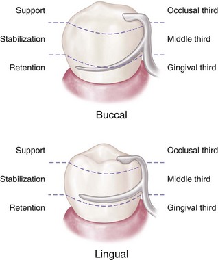
The extracoronal retainer uses mechanical resistance to displacement through components placed on or attached to the external surfaces of an abutment tooth. The extracoronal retainer is available in three principal forms. The clasp-type retainer (Figures 7-8 and 7-9), the form used most commonly, retains through a flexible clasp arm. This arm engages an external surface of an abutment tooth in an area cervical to the greatest convexity of the tooth, or it engages a depression prepared to receive the terminal tip of the arm. The other forms both involve manufactured attachments and include interlocking components or the use of a spring-loaded device that engages a tooth contour to resist occlusal displacement. Another type is a manufactured attachment, which uses flexible clips or rings that engage a rigid component that is cast or attached to the external surface of an abutment crown.
Criteria for Selecting a Given Clasp Design
When a particular clasp design is selected for a given situation, its function and limitations must be carefully evaluated. Extracoronal direct retainers, as part of the clasp assembly, should be considered as components of a removable partial denture framework. They should be designed and located to perform the specific functions of support, stabilization, reciprocation, and retention. It does not matter whether the direct retainer-clasp assembly components are physically attached to each other, or originate from major and minor connectors of the framework (see Figures 1-2 and 1-3, B-E). If attention is directed to the separate function of each component of the direct retainer-clasp assembly, then selection of a direct retainer is simplified.
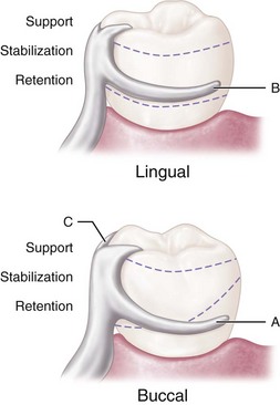
No confusion should exist between the choice of clasp arm and the purpose for which it is used. Either type of cast clasp arm (bar or circumferential) may be made tapered and retentive, or nontapered (rigid) and nonretentive. The choice depends on whether it is used for retention, stabilization, or reciprocation. An occlusal rest, such as in the RPI (rest, proximal plate, and I-bar component parts of the clasp assembly) concept, may be used rather than a reciprocal clasp arm to satisfy the need for encirclement, provided it is located in such a way that it can accomplish the same purpose (Figure 7-10; see also Figure 7-9). The addition of a lingual apron to a cast reciprocal clasp arm alters neither its primary purpose nor the need for proper location to accomplish that purpose.
Types of Clasp Assemblies
Clasps Designed to Accommodate Functional Movement
RPI, RPA, and Bar Clasp
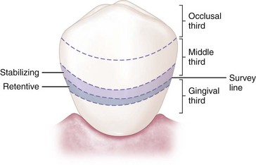
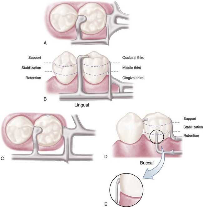
Mesial rest concept clasps have been proposed to accomplish movement accommodation by changing the fulcrum location. This concept includes the RPI and RPA [rest, proximal plate, Akers] clasps. The RPI is a current concept of bar clasp design that refers to the rest, proximal plate, and I-bar component parts of the clasp assembly. Basically, this clasp assembly consists of a mesio-occlusal rest with the minor connector placed into the mesiolingual embrasure, but not contacting the adjacent tooth (Figure 7-11, A). A distal guiding plane, extending from the marginal ridge to the junction of the middle and gingival thirds of the abutment tooth, is prepared to receive a proximal plate (Figure 7-11, B). The buccolingual width of the guiding plane is determined by the proximal contour of the tooth (Figure 7-11, A and C). The proximal plate, in conjunction with the minor connector supporting the rest, provides the stabilizing and reciprocal aspects of the clasp assembly. The I-bar should be located in the gingival third of the buccal or labial surface of the abutment in a 0.01-inch undercut (Figure 7-11, D). The whole arm of the I-bar should be tapered to its terminus, with no more than 2 mm of its tip contacting the abutment. The retentive tip contacts the tooth from the undercut to the height of contour (Figure 7-11, E). This area of contact, along with the rest and proximal plate contact, provides stabilization through encirclement (see Figure 7-11, C). The horizontal portion of the approach arm must be located at least 4 mm from the gingival margin and even farther if possible.
Three basic approaches to the application of the RPI system may be used. The location of the rest, the design of the minor connector (proximal plate) as it relates to the guiding plane, and the location of the retentive arm are factors that influence how this clasp system functions. Variations in these factors provide the basis for differences among these approaches. All advocate the use of a rest located mesially on the primary abutment tooth adjacent to the extension base area. One approach recommends that the guiding plane and the corresponding proximal plate minor connector should extend the entire length of the proximal tooth surface, with physiologic tissue relief eliminating impingement of the free gingival margin (Figure 7-12). A second approach suggests that the guiding plane and the corresponding proximal plate minor connector should extend from the marginal ridge to the junction of the middle and gingival thirds of the proximal tooth surface (Figure 7-13). Both approaches recommend that the retaining clasp arm should be located in the gingival third of the buccal or labial surface of the abutment in a 0.01-inch undercut. Placement of the retaining clasp arm generally occurs in an undercut located at the greatest mesiodistal prominence of the tooth or adjacent to the extension base area (Figure 7-14, A and B). The third approach favors a proximal plate minor connector that contacts approximately 1 mm of the gingival portion of the guiding plane (Figure 7-15, A) and a retentive clasp arm located in a 0.01-inch undercut in the gingival third of the tooth at the greatest prominence or toward the mesial away from the edentulous area (Figure 7-14, C). If the abutment teeth demonstrate contraindications for a bar-type clasp (i.e., exaggerated buccal or lingual tilts, severe tissue undercut, or a shallow buccal vestibule) and the desirable undercut is located in the gingival third of the tooth away from the extension base area, a modification should be considered for the RPI system (the RPA clasp) (Figure 7-15, B). Application of each approach is predicated on the distribution of load to be applied to the tooth and edentulous ridge.
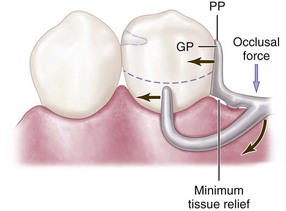
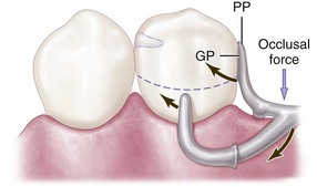
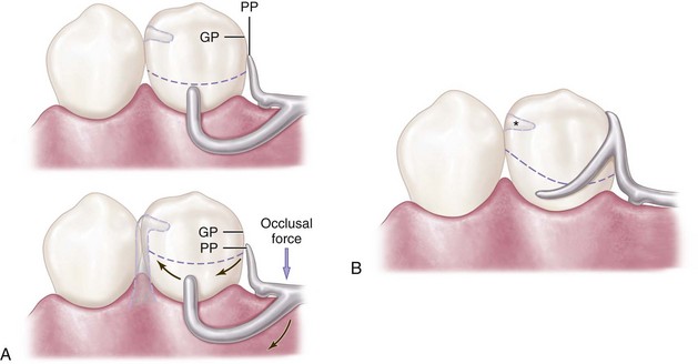
Figure 7-13 Bar clasp assembly in which the guiding plane (GP) and the corresponding proximal plate (PP) extend from the marginal ridge to the junction of the middle and gingival thirds of the proximal tooth surface. This decrease (compared with Figure 7-23) in amount of surface area contact of the proximal plate on the guiding plane more evenly distributes functional force between the tooth and the edentulous ridge.
The bar clasp, which gave rise to the RPI, is discussed here because of this association. It may not be configured to allow functional movement, but it can be. The term bar clasp is generally preferred over the less descriptive term Roach clasp arm. Reduced to its simplest term, the bar clasp arm arises from the denture framework or a metal base and approaches the retentive undercut from a gingival direction (see Figure 7-11). The bar clasp arm has been classified by the shape of the retentive terminal. Thus it has been identified as a T, modified T, I, or Y. The form the terminal takes is of little significance as long as it is mechanically and functionally effective, covers as little tooth surface as possible, and displays as little metal as possible.
In most situations, the bar clasp arm can be used with tooth-supported partial dentures, with tooth-supported modification areas, or when an undercut that can be logically approached with a bar clasp arm lies on the side of an abutment tooth adjacent to a distal extension base (Figure 7-16). If a tissue undercut prevents the use of a bar clasp arm, a mesially originating ring clasp, a cast, or a wrought-wire clasp or reverse-action clasp may be used. Preparation of adjacent abutments (natural teeth) to receive any type of interproximal direct retainer, traversing from lingual to buccal surfaces, is most difficult to adequately accomplish. Inevitably the relative size of the occlusal table is increased, contributing to undesirable and additional functional loading.
Specific indications for use of a bar clasp arm include (1) when a small degree of undercut (0.01 inch) exists in the cervical third of the abutment tooth, which may be approached from a gingival direction; (2) on abutment teeth for tooth-supported partial dentures or tooth-supported modification areas (Figure 7-17); (3) in distal extension base situations; and (4) in situations in which esthetic considerations must be accommodated and a cast clasp is indicated. Thus use of the bar clasp arm is contraindicated when a deep cervical undercut exists or when a severe tooth and/or tissue undercut exists, either of which must be bridged by excessive blockout. When severe tooth and ti/>
Stay updated, free dental videos. Join our Telegram channel
VIDEdental - Online dental courses


