Instruments and Equipment for Tooth Preparation
Hand Instruments for Cutting
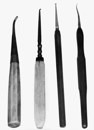
The early hand-operated instruments—with their large, heavy handles (Fig. 6-1) and inferior (by present standards) metal alloys in the blades—were cumbersome, awkward to use, and ineffective in many situations. As the commercial manufacture of hand instruments increased, and dentists began to express ideas about tooth preparation, it became apparent that some scheme for identifying these instruments was necessary. Among his many contributions to modern dentistry, Black is credited with the first acceptable nomenclature for and classification of hand instruments.1 His classification system enabled dentists and manufacturers to communicate more clearly and effectively about instrument design and function.
Terminology and Classification
Categories
The hand instruments used in the dental operatory may be categorized as (1) cutting (excavators, chisels, and others) or (2) non-cutting (amalgam condensers, mirrors, explorers, probes).1 Excavators may be subdivided further into ordinary hatchets, hoes, angle formers, and spoons. Chisels are primarily used for cutting enamel and may be subdivided further into straight chisels, curved chisels, bin-angle chisels, enamel hatchets, and gingival margin trimmers. Other cutting instruments may be subdivided as knives, files, scalers, and carvers. In addition to the cutting instruments, a large group of noncutting instruments (see Fig. 14-21, D and E) is also in use.
Design
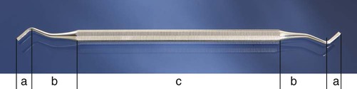
Most hand instruments, regardless of use, are composed of three parts: handle, shank, and blade (Fig. 6-2). For many non-cutting instruments, the part corresponding to the blade is termed nib. The end of the nib, or working surface, is known as face. The blade or nib is the working end of the instrument and is connected to the handle by the shank. Some instruments have a blade on both ends of the handle and are known as double-ended instruments. The blades are of many designs and sizes, depending on their functions.
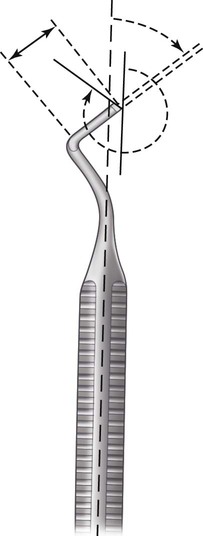
Balance is accomplished by designing the angles of the shank so that the cutting edge of the blade lies within the projected diameter of the handle and nearly coincides with the projected axis of the handle (Fig. 6-3; see also Fig. 6-2). For optimal anti-rotational design, the blade edge must not be off-axis by more than 1 to 2 mm. All dental instruments and equipment need to satisfy this principle of balance.
Shank Angles
The functional orientation and length of the blade determine the number of angles in the shank necessary to balance the instrument. Black classified instruments on the basis of the number of shank angles as mon-angle (one), bin-angle (two), or triple-angle (three).2 Instruments with small, short blades may be easily designed in mon-angle form while confining the cutting edge within the required limit. Instruments with longer blades or more complex orientations may require two or three angles in the shank to bring the cutting edge close to the long axis of the handle. Such shanks are termed contra-angled.
Names
Black classified all of the instruments by name.2 In addition, for hand-cutting instruments, he developed a numeric formula to characterize the dimensions and angles of the working end (see the next section for details of the formula). Black’s classification system by instrument name categorized instruments by (1) function (e.g., scaler, excavator), (2) manner of use (e.g., hand condenser), (3) design of the working end (e.g., spoon excavator, sickle scaler), or (4) shape of the shank (e.g., mon-angle, bin-angle, contra-angle).2 These names were combined to form the complete description of the instrument (e.g., bin-angle spoon excavator).
Formulas
Cutting instruments have formulas describing the dimensions and angles of the working end. These are placed on the handle using a code of three or four numbers separated by dashes or spaces (e.g., 10–8.5–8–14) (see Fig. 6-3). The first number indicates the width of the blade or primary cutting edge in tenths of a millimeter (0.1 mm) (e.g., 10 = 1 mm). The second number of a four-number code indicates the primary cutting edge angle, measured from a line parallel to the long axis of the instrument handle in clockwise centigrades. The angle is expressed as a percent of 360 degrees (e.g., 85 = 85% × 360 degrees = 306 degrees). The instrument is positioned so that this number always exceeds 50. If the edge is locally perpendicular to the blade, this number is normally omitted, resulting in a three-number code. The third number (second number of a three-number code) indicates the blade length in millimeters (e.g., 8 = 8 mm). The fourth number (third number of a three-number code) indicates the blade angle, relative to the long axis of the handle in clockwise centigrade (e.g., 14 = 50 degrees). For these measurements, the instrument is positioned such that this number is always 50 or less. The most commonly used hand instruments, including those specified in this text, are shown in Figures 6-5 through 6-9 with their formulas indicated.
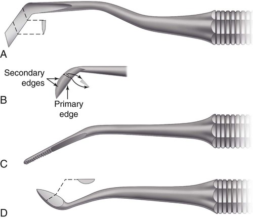
Bevels
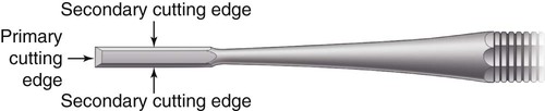
Most hand cutting instruments have on the end of the blade a single bevel that forms the primary cutting edge. Two additional edges, called secondary cutting edges, extend from the primary edge for the length of the blade (Fig. 6-4). Bi-beveled instruments such as ordinary hatchets have two bevels that form the cutting edge (Fig. 6-5, A).
 ). C, Angle former (12–85–5–8).
Certain single-beveled instruments such as spoon excavators (Fig. 6-6) and gingival margin trimmers (Fig. 6-7, B and C) are used with a scraping or lateral cutting motion. Others such as enamel hatchets (see Fig. 6-7, A) may be used with a planing or direct cutting motion and a lateral cutting motion. For such single-beveled designs, the instruments must be made in pairs, with the bevels on opposite sides of the blade. Such instruments are designated as right beveled or left beveled and are indicated by appending the letter R or L to the instrument formula. To determine whether the instrument has a right or left bevel, the primary cutting edge is held down and pointing away, and if the bevel appears on the right side of the blade, it is the right instrument of the pair. This instrument, when used in a scraping motion, is moved from right to left. The opposite holds true for the left instrument of the pair. One instrument is suited for work on one side of the preparation, and the other is suited for the opposite side of the preparation.
 ). C, Gingival margin trimmer (
 ).
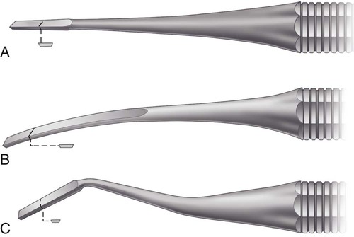
).Instruments having the cutting edge perpendicular to the axis of the handle (Fig. 6-8), such as bin-angle chisels (see Fig. 6-8, C), instruments with a slight blade curvature (Wedelstaedt chisels) (see Fig. 6-8, B), and hoes (see Fig. 6-5, B), are single-beveled and not designated as rights or lefts but as having a mesial bevel or a distal bevel. If when one observes the inside of the blade curvature (or the inside of the angle at the junction of the blade and shank) the primary bevel is not visible, the instrument has a distal bevel. Conversely, if the primary bevel can be seen (from the same viewpoint), the instrument has a mesial or reverse bevel (see Fig. 6-8).
 ). C, Bin-angle (10–7–8).
Applications
Excavators
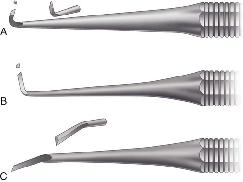
The four subdivisions of excavators are (1) ordinary hatchets, (2) hoes, (3) angle-formers, and (4) spoons. An ordinary hatchet excavator has the cutting edge of the blade directed in the same plane as that of the long axis of the handle and is bi-beveled (see Fig. 6-5, A). These instruments are used primarily on anterior teeth for preparing retentive areas and sharpening internal line angles, particularly in preparations for direct gold restorations.
The hoe excavator has the primary cutting edge of the blade perpendicular to the axis of the handle (see Fig. 6-5, B). This type of instrument is used for planing tooth preparation walls and for forming line angles. It is commonly used in Class III and V preparations for direct gold restorations. Some sets of cutting instruments contain hoes with longer and heavier blades, with the shanks contra-angled. These are intended for use on enamel or posterior teeth.
A special type of excavator is the angle-former (see Fig. 6-5, C). It is used primarily for sharpening line angles and creating retentive features in dentin in preparation for gold restorations. It also may be used in placing a bevel on enamel margins. It is mon-angled and has the primary cutting edge at an angle (other than 90 degrees) to the blade. It may be described as a combination of a chisel and a gingival margin trimmer. It is available in pairs (right and left).
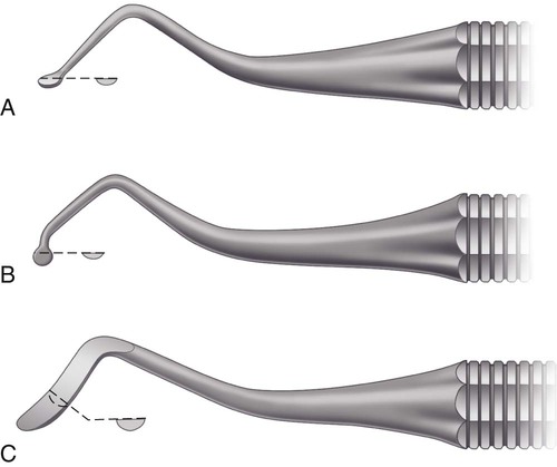
Spoon excavators (see Fig. 6-6) are used for removing caries and carving amalgam or direct wax patterns. The blades are slightly curved, and the cutting edges are either circular or claw-like. The circular edge is known as a discoid, whereas the claw-like blade is termed cleoid (Fig. 6-9, C and D). The shanks may be bin-angled or triple-angled to facilitate accessibility.
Chisels
Chisels are intended primarily for cutting enamel and may be grouped as (1) straight, slightly curved, or bin-angle; (2) enamel hatchets; and (3) gingival margin trimmers. The straight chisel has a straight shank and blade, with the bevel on only one side. Its primary edge is perpendicular to the axis of the handle. It is similar in design to a carpenter’s chisel (see Fig. 6-8, A). The shank and blade of the chisel also may be slightly curved (Wedelstaedt design) (see Fig. 6-8, B) or may be bin-angled (see Fig. 6-8, C). The force used with all these chisels is essentially a straight thrust. A right or left type is not needed in a straight chisel because a 180-degree turn of the instrument allows for its use on either side of the preparation. The bin-angle and Wedelstaedt chisels have the primary cutting edges in a plane perpendicular to the axis of the handle and may have either a distal bevel or a mesial (reverse) bevel. The blade with a distal bevel is designed to plane a wall that faces the blade’s inside surface (see Fig. 6-5, A and B). The blade with a mesial bevel is designed to plane a wall that faces the blade’s outside surface (see Fig. 6-8, B and C).
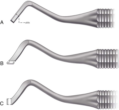
The enamel hatchet is a chisel similar in design to the ordinary hatchet except that the blade is larger, heavier, and beveled on only one side (see Fig. 6-7, A). It has its cutting edges in a plane that is parallel with the axis of the handle. It is used for cutting enamel and comes as right or left types for use on opposite sides of the preparation.
The gingival margin trimmer is designed to produce a proper bevel on gingival enamel margins of proximo-occlusal preparations. It is similar in design to the enamel hatchet except the blade is curved (similar to a spoon excavator), and the primary cutting edge is at an angle (other than perpendicular) to the axis of the blade (see Fig. 6-7, B and C). It is made as right and left types. It also is made so that a right and left pair is either a mesial pair or a distal pair. When the second number in the formula is 90 to 100, the pair is used on the distal gingival margin. When this number is 75 to 85, the pair is used to bevel the mesial margin. The 100 and 75 pairs are for inlay–onlay preparations with steep gingival bevels. The 90 and 85 pairs are for amalgam preparations with gingival enamel bevels that decline gingivally only slightly. Among other uses for these instruments is the rounding or beveling of the axiopulpal line angle of two-surface preparations.
Other Cutting Instruments
Other hand cutting instruments such as the knife, file, and discoid–cleoid instrument are used for trimming restorative material rather than for cutting tooth structure. Knives, known as finishing knives, amalgam knives, or gold knives, are designed with a thin, knife-like blade that is made in various sizes and shapes (see Fig. 6-9, A and B). Knives are used for trimming excess restorative material on the gingival, facial, or lingual margins of a proximal restoration or trimming and contouring the surface of a Class V restoration. Sharp secondary edges on the heel aspect of the blade are useful in a scrape–pull mode.
Files (see Fig. 6-9, C) also can be used to trim excess restorative material. They are particularly useful at gingival margins. The blades of the file are extremely thin, and the teeth of the instrument on the cutting surfaces are short and designed to make the file a push instrument or a pull instrument. Files are manufactured in various shapes and angles to allow access to restorations.
The discoid-cleoid (see Fig. 6-9, D and E) instrument is used principally for carving occlusal anatomy in unset amalgam restorations. It also may be used to trim or burnish inlay–onlay margins. The working ends of this instrument are larger than the discoid or cleoid end of an excavator.
Hand Instrument Techniques
Four grasps are used with hand instruments: (1) modified pen, (2) inverted pen, (3) palm-and-thumb, and (4) modified palm-and-thumb. The conventional pen grasp is not an acceptable instrument grasp (Fig. 6-10, A).
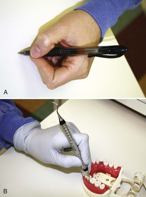
Modified Pen Grasp
The grasp that permits the greatest delicacy of touch is the modified pen grasp (see Fig. 6-10, B). As the name implies, it is similar, but not identical, to that used in holding a pen. The pads of the thumb and of the index and middle fingers contact the instrument, while the tip of the ring finger (or tips of the ring and little fingers) is placed on a nearby tooth surface of the same arch as a rest. The palm of the hand generally is facing away from the operator. The pad of the middle finger is placed near the topside of the instrument; by this finger working with the wrist and the forearm, cutting or cleaving pressure is generated on the blade. The instrument should not be allowed to rest on or near the first joint of the middle finger as in the conventional pen grasp (see Fig. 6-10, A). Although this latter position may appear to be more comfortable, it limits the application of pressure. A balanced instrument design allows the application of suitable force without the instrument tending to rotate in the fingers (see Fig. 6-3).
Palm-and-Thumb Grasp
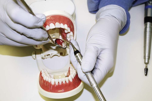
The palm-and-thumb grasp is similar to that used for holding a knife while paring an apple. The handle is placed in the palm of the hand and grasped by all the fingers, while the thumb is free of the instrument, and the rest is provided by supporting the tip of the thumb on a nearby tooth of the same arch or on a firm, stable structure. For suitable control, this grasp requires careful use during cutting. An example of an appropriate use is holding a handpiece for cutting incisal retention for a Class III preparation on a maxillary incisor (Fig. 6-12).
Modified Palm-and-Thumb Grasp
The modified palm-and-thumb grasp may be used when it is feasible to rest the thumb on the tooth being prepared or the adjacent tooth (Fig. 6-13). The handle of the instrument is held by all four fingers, whose pads press the handle against the distal area of the palm and the pad and first joint of the thumb. Grasping the handle under the first joints of the ring finger and little finger provides stabilization. This grip fosters control against slippage.
Rests
A proper instrument grasp must include a firm rest to steady the hand during operating procedures. When the modified pen grasp and the inverted pen grasp are used, rests are established by placing the ring finger (or both ring and little fingers) on a tooth (or teeth) of the same arch and as close to the operating site as possible (see Figs. 6-10 and 6-11). The closer the rest areas are to the operating area, the more reliable they are. When the palm-and-thumb grasps are used, rests are created by placing the tip of the thumb on the tooth being operated on, on an adjacent tooth, or on a convenient area of the same arch (see Figs. 6-12 and 6-13).
Contemporary Powered Cutting Equipment
Rotary Power Cutting Equipment
Rotary Speed Ranges for Different Cutting Applications
Although intact tooth structure can be removed by an instrument rotating at low speeds, it is a traumatic experience for the patient and the dentist. Low-speed cutting is ineffective, is time-consuming, and requires a relatively heavy force application; this results in heat production at the operating site and produces vibrations of low frequency and high amplitude. Heat and vibration are the main sources of patient discomfort.3 At low speeds, burs have a tendency to roll out of the tooth preparation and mar the proximal margin or tooth surface. In addition, carbide burs do not last long because their brittle blades are easily broken at low speeds. Many of these disadvantages of low-speed operation do not apply when the objective is some procedure other than cutting tooth structure. The low-speed range is used for cleaning teeth, caries excavation, and finishing and polishing procedures. At low speeds, tactile sensation is better, and generally, overheating of cut surfaces is less likely. The availability of a low-speed option provides a valuable adjunct for many dental procedures.
For infection control, all dental handpieces are now sterilized, but the process is associated with some challenges. Continual sterilization can produce degradation in clinical performance (longevity, power, turbine speed, fiberoptic transmission, eccentricity, noise, chuck performance, visibility angle, interocclusal clearance, water spray pattern).4 Most handpieces require re-oiling after sterilization, and excess oil may be sprayed during the start-up operation. Several companies offer automated equipment to precisely clean and lubricate the handpiece after each use. It is recommended to run the handpiece for a few seconds before initiating dental procedures in which the deposition of oil spray onto tooth structure might interfere with processes such as dental adhesion.
Laser Equipment
Lasers are devices that produce beams of coherent and very-high-intensity light. Numerous current and potential uses of lasers in dentistry have been identified that involve the treatment of soft tissues and the modification of hard tooth structures.5,6 The word laser is an acronym for “light amplification by stimulated emission of radiation.” A crystal or gas is excited to emit photons of a characteristic wavelength that are amplified and filtered to make a coherent light beam. The effects of the laser depend on the power of the beam and the extent to which the beam is absorbed.
Other Equipment
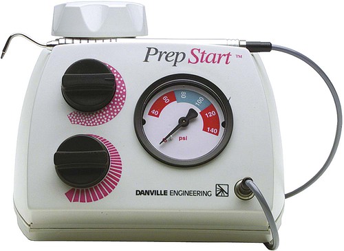
Contemporary air abrasion equipment (Fig. 6-14) is helpful for stain removal, debriding pits and fissures before sealing, and micromechanical roughening of surfaces to be bonded (enamel, cast metal alloys, or porcelain).7 This approach works well when organic material is being removed and when only a limited amount of enamel or dentin is involved. Although promoted for caries excavation, air abrasion cannot produce well-defined preparation wall and margin details that are possible with conventional rotary cutting techniques. Generally, the finest stream of abrading particles still generates an effective cutting width that is far greater than the width of luted cement margins or the errors tolerable in most caries excavations. Roughening of surfaces to be bonded, luted, or repaired is an advantage and can occur intraorally or extraorally, depending on the situation. Roughening by air abrasion by itself is not a substitute for acid-etching techniques. Roughening improves bonding. Acid-etching alone or after roughening, however, always produces a better bond than air abrasion alone.8
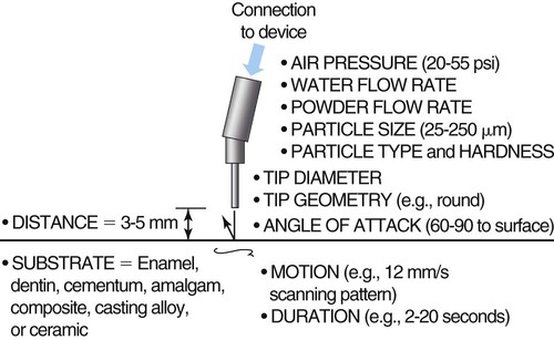
Air abrasion techniques rely on the transfer of kinetic energy from a stream of powder particles on the surface of tooth structure or a restoration to produce a fractured surface layer, resulting in roughness for bonding or disruption for cutting. The energy transfer event is affected by many things, including powder particle, pressure, angulation, surface composition, and clearance angle variables (Fig. 6-15). The most common error made by operators of air abrasion units is holding the tip at the wrong distance from the surface for the desired action. Greater distances significantly reduce the energy of the stream.9 Short distances may produce unwanted cutting actions, such as when only surface stain removal is being attempted. The potential for unwanted cutting is a significant problem when employing an air-polishing device (e.g., Prophy Jet) to clean the surfaces of dentin and enamel.10–13 When used properly, however, units designed for air polishing tooth surfaces can be quite efficient and effective (Fig. 6-16).
Rotary Cutting Instruments
Common Design Characteristics
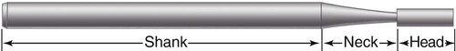
Despite the great variation among rotary cutting instruments, they share certain design features. Each instrument consists of three parts: (1) shank, (2) neck, and (3) head (Fig. 6-17). Each has its own function, influencing its design and the materials used for its construction. The term shank has different meanings as applied to rotary instruments and to hand instruments.
Shank Design
The shank is the part that fits into the handpiece, accepts the rotary motion from the handpiece, and provides a bearing surface to control the alignment and concentricity of the instrument. The shank design and dimensions vary with the handpiece for which it is intended. The American Dental Association (ADA) Specification No. 23 for dental excavating burs includes five classes of instrument shanks.14 Three of these (Fig. 6-18)—the straight handpiece shank, the latch-type angle handpiece shank, and the friction-grip angle handpiece shank—are commonly encountered. The shank portion of the straight handpiece instrument is a simple cylinder. It is held in the handpiece by a metal chuck that accepts a range of shank diameters. Precise control of the shank diameter is not as crucial as for other shank designs. Straight handpiece instruments are now rarely used for preparing teeth except for caries excavation. They are commonly used, however, for finishing and polishing completed restorations.
Stay updated, free dental videos. Join our Telegram channel
VIDEdental - Online dental courses


