6 Clinical Case Presentations
6.1 Early and Conventional Loading
6.1.1 Early Loading of Two Implants in the Mandible and Final Restoration with a Retentive-Anchor-Supported RDP
A.G.T. Payne, A. Tawse-Smith, R.K. De Silva, W.J. Duncan
A 63-year-old male edentulous and maladaptive patient presented with an inability to wear his existing complete maxillary and mandibular dentures. He had been edentulous for 41 years, and there had been three unsuccessful attempts by dentists to provide complete dentures for him. Efforts to wear both complete dentures were always initially encouraging, but over time, he invariably found that he was unable to wear the complete mandibular denture, and this pattern had persisted for 20 years. After seeing local newspaper advertisements, he requested having his complete mandibular denture stabilized with implants.
According to the Prosthodontic Diagnostic Index, the patient was diagnosed as class II, with evidence of favorable minimal mandibular residual ridge resorption. Using both panoramic and lateral cephalometric radiographs, the residual bone height was found to be in the region of 20 mm, which resisted horizontal and vertical movement of the denture base (Figs 1a-b). The location of the muscle attachments had limited the influence on the denture base stability and retention. The edentulous maxilla was of category B, and there were minor modifiers in terms of the psychological aspects of the severe gagging response. Although the patient was deemed suitable for a mandibular fixed implant-supported bridge, he preferred a removable overdenture for financial reasons.
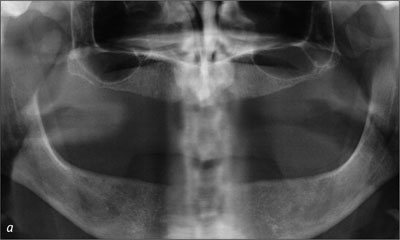
Fig 1a Baseline panoramic radiograph.
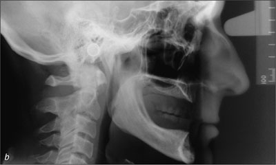
Fig 1b Baseline lateral cephalometric radiograph.
To facilitate a 2-week early-loading protocol, new diagnostic complete maxillary and mandibular dentures were fabricated using standard procedures, and the vertical dimension of occlusion was established (Figs 2a-b). Gagging responses related to the maxillary denture dictated that the posterior border in the region of the post-dam be shortened to facilitate wear. Even with this modification, the patient was only able to tolerate his conventional complete mandibular denture for a limited time.
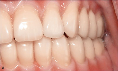
Fig 2a Diagnostic complete dentures, left side.
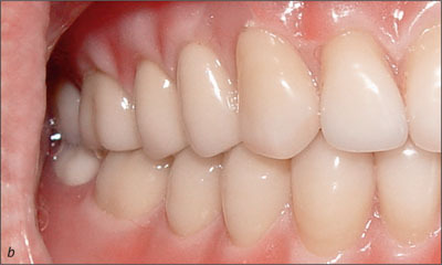
Fig 2b Diagnostic complete dentures, right side.
The preoperative diagnostic panoramic radiograph (Scanora, Soridex, Helsinki, Finland) was used to identify the implant lengths required. On the day of surgery, 2 g of amoxicillin were given orally, 1 hour before the operation. The patient was instructed to rinse his mouth with 0.2% chlorhexidine digluconate solution (Savacol, Colgate Oral Care, Sydney, Australia) for 1 minute prior to the operation.
Two Straumann Standard RN SLA implants of 14 mm length were placed using the original Straumann non-submerged protocol. Analysis during surgery and of the radiographs defined the case as Lekholm and Zarb bone quantity B and bone quality 3. The interimplant distance was determined at 22 mm by first marking the midline with a round bur (Fig 3). Then, using the pilot drills, sites were prepared 11 mm to either side of midline using a modified implant-paralleling device.
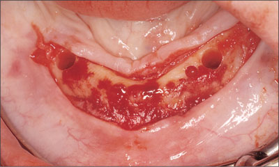
Fig 3 Determining the inter-implant distance using a midline mark as reference.
Finally, using the alignment pins (Ø 2.2 mm to 3.5 mm) supplemented with depth gauges, the osteotomies were completed with a 4.1-mm tap (Figs 4 to 6).Resonance frequency analysis (Osstell, Integration Diagnostics, Göte-borg, Sweden) confirmed the initial primary stability with ISQ readings of 62.
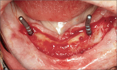
Fig 4 Alignment pins.
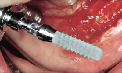
Fig 5 The osteotomies are completed and the implants placed.
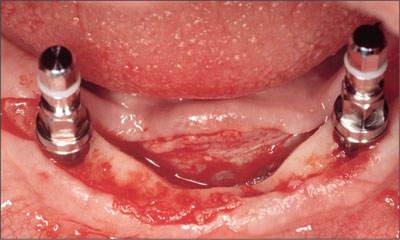
Fig 6 Implants placed with mounts still connected.
A modification to the standard protocol was that instead of using healing caps on the implants, both retentive anchors were placed during the surgery and torqued to 35 Ncm (Fig 7). Mucoperiosteal flap closure was then completed using interrupted or horizontal mattress sutures (Vicryl 4-0, Ethicon, Johnson & Johnson, Brussels, Belgium; Fig 8).
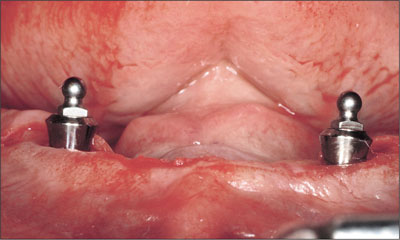
Fig 7 Retentive anchors placed.
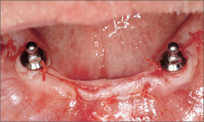
Fig 8 Flap after suturing.
Immediately after surgery, a denture tissue conditioner (Viscogel, DeTrey, Weybridge, England) was applied to a generously relieved undersurface (Fig 9), and the patient was permitted to wear his complete mandibular denture with his complete maxillary denture postoperatively. The patient was advised not to brush the implants during the first week, and the sutures were removed on day 7. The patient was placed on a soft diet for the first 2 weeks and a strict regime of denture removal at night. The postoperative care protocol also included twice daily 0.2% chlorhexidine digluconate rinses and daily bilateral peri-implant application of a 0.2% chlorhexidine digluconate gel (PerioGard, Colgate Oral Care, Sydney, Australia) using the denture as a reservoir.
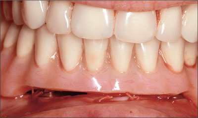
Fig 9 Application of a denture tissue conditioner.
Exactly 2 weeks after surgery, following mucosal healing and in line with the planned early-loading protocol, the tissue conditioner was removed from the mandibular denture and prepared for a closed-mouth reline impression (Impregum, 3M ESPE, Seefeld, Germany) (Fig 10).
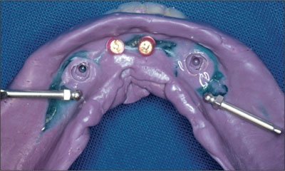
Fig 10 Two abutment analogues and 2 matrices.
Recommended laboratory procedures were followed, with transfer pins for the retentive anchors being placed into the impression, and the laboratory models were poured in type III die stone. The Dalla Bona-type gold matrices were placed onto the transfer pins, and blockout procedures were followed and the dentures processed. The final mandibular two-implant overdenture had old-style Dalla Bona-type gold matrices included on the intaglio surface (Fig 11).
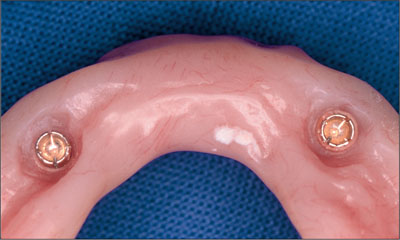
Fig 11 Dalla Bona-type gold matrices on the tissue side.
Prior to the delivery of the prostheses the following day, the labial periphery of the mandibular implant overdenture was reduced in the region of the implants to minimize the possibility of irritation leading to peri-abutment or peri-implant mucosal enlargement (hyperplasia). The intaglio surfaces of the complete maxillary denture and the mandibular two-implant overdenture were checked using pressure-disclosing paste, and the occlusion was refined using a full remount and selective grinding procedure. Oral hygiene instructions were provided to the patient on overdenture insertion and they were reinforced with professional cleaning at the annual recall.
The patient was recalled at 6 weeks (Figs 12 and 13), 12 weeks (Fig 14), and annually thereafter. Minor adjustments to the denture contours were made to facilitate comfortable function. With this completion of treatment, the patient immediately reported a return to full-time denture wearing and being able to eat a wide variety of foods. As a result, his self-confidence in front of his work colleagues had improved dramatically.
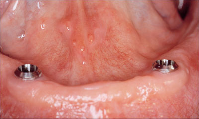
Fig 12 Recall at 6 weeks. The ball attachments were removed to take resonance frequency readings at implant level to assess implant stability.
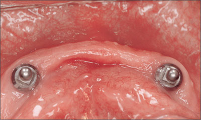
Fig 13 Recall at 6 weeks.
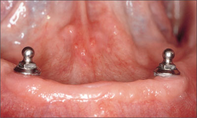
Fig 14 Recall at 12 weeks.
Ten-year follow-up
The patient was followed through a 10-year recall period up to 2008, with standardized panoramic radiographs (Figs 15to 18).
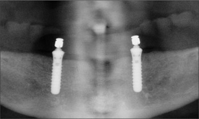
Fig 15 Panoramic radiograph, recall at 6 weeks.
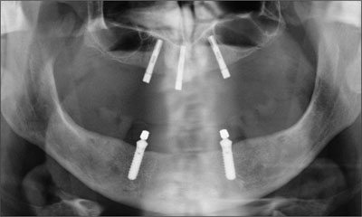
Fig 16 Panoramic radiograph, recall at 1 year.
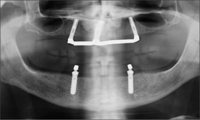
Fig 17 Panoramic radiograph, recall at 5 years.
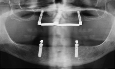
Fig 18 Panoramic radiograph, recall at 10 years.
In addition, intraoral radiographs of the coronal parts of the implants indicated stable peri-implant bone conditions and negligible crestal bone loss (Figs 19a-b to 22a-b).
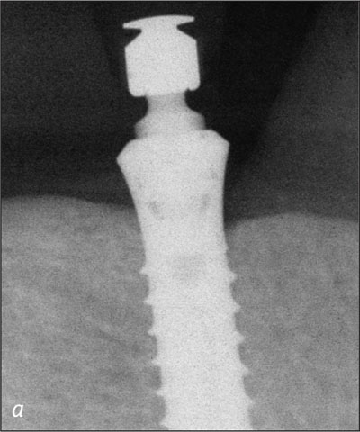
Fig 19a Right implant, baseline at 2 weeks.
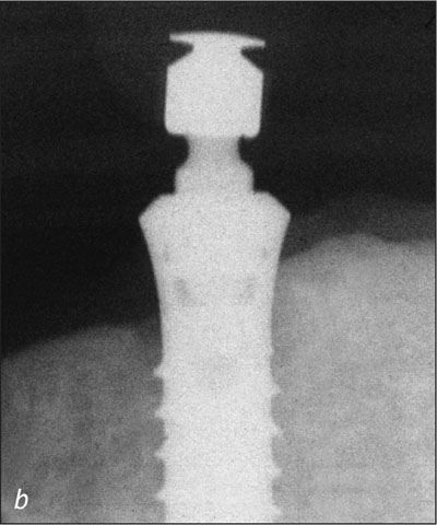
Fig 19b Left implant, baseline at 2 weeks.
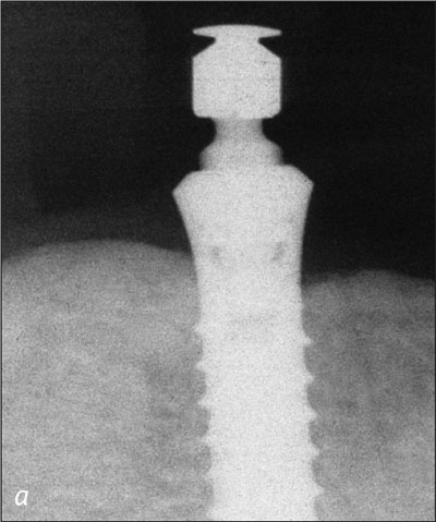
Fig 20a Right implant, recall at 1 year.
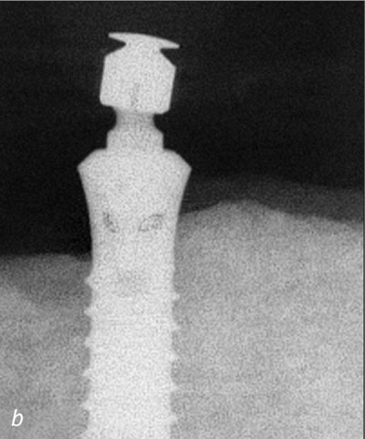
Fig 20b Left implant, recall at 1 year.
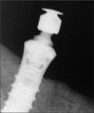
Fig 21a Right implant, recall at 5 years.
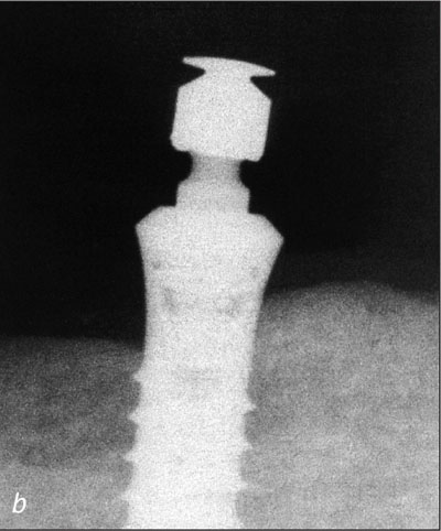
Fig 21b Left implant, recall at 5 years.
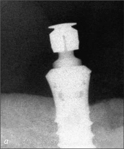
Fig 22a Right implant, recall at 10 years.
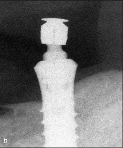
Fig 22b Left implant, recall at 10 years.
The sequential resonance frequency readings indicated improved osseointegration over time. The peri-implant mucosal response around the implants was excellent through the recall period (Figs 23a-c and 24a-c).
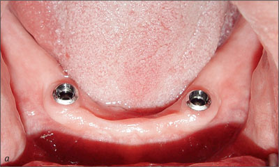
Fig 23a Recall at 5 years with retentive anchors removed.
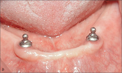
Fig 23b Recall at 5 years.
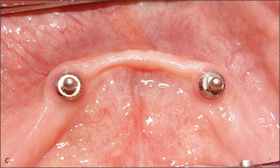
Fig 23c Recall at 5 years.
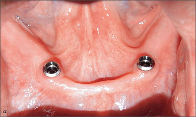
Fig 24a Recall at 10 years with retentive anchors removed.
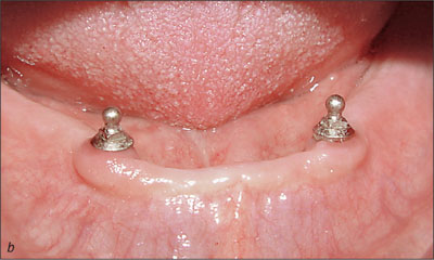
Fig 24b Recall at 10 years.
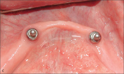
Fig 24c Recall at 10 years.
During this 10-year follow-up period, the patient was also provided with three maxillary implants between year 1 and year 3 to support a bar-retained overdenture in the maxilla in order to complete the rehabilitation of his edentulous predicament. A different implant system was used (Southern Implants, Irene, South Africa).
Prosthodontic maintenance was minimal related to the activation of the old-style Dalla Bona-type gold matrices, using the recommended activating or deactivating instruments (Figs 25 and 26).
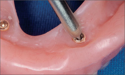
Fig 25 Minimal prosthetic maintenance was required.
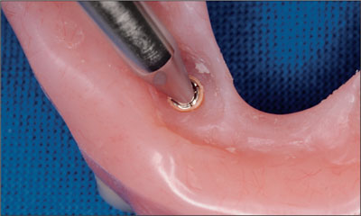
Fig 26 Prosthetic maintenance was performed using the recommended activating or deactivating instruments.
There were no fractures of matrix lamellae during the 10-year period, indicating excellent longevity (Fig 27).
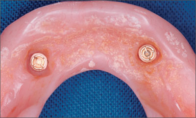
Fig 27 Original Dalla Bona-type gold matrices.
A decision was made to replace these matrices when the mandibular implant overdenture was relined at the 7-year recall. The original Dalla Bona-type gold matrices were replaced with new elliptical Straumann gold matrices with lamellae inserts to facilitate easier replacement over the next 10-year period (Figure 28).
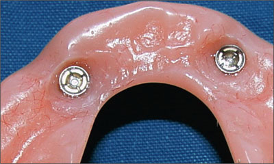
Fig 28 Replacement elliptical Straumann gold matrices.
Using the recommended screwdriver, the new elliptical matrices were adjusted to obtain the correct retention for the patient. There was no evidence of wear of the spherical portions of the retentive anchors after the 10-year period.
Acknowledgments
Laboratory Procedures
Dental Technician Neil Waddell – Dunedin, New Zealand
Dental Technician Ian van Staden – Dunedin, New Zealand
6.1.2 Conventional Loading of Two Implants in the Mandible and Final Restoration with a Locator-Supported RDP
A. Boeckler, D. Morton
An 83-year-old male patient requested treatment for his existing maxillary complete overdenture and mandibular complete denture. He reported no general medical conditions of significance that would affect his dental treatment and was taking no prescription medication. He denied suffering from oral pain and displayed no evidence of parafunctional habits or temporomandibular joint disorder.
Oral and radiographic evaluation revealed two retained maxillary teeth (13 and 15) supporting prefabricated ball-shaped attachments. Both teeth were mobile and associated with active periodontal disease and extensive dental caries; these were considered non-restorable and were recommended for extraction.
The patient’s existing complete maxillary and mandibular prostheses were approximately 2 years old. He was very satisfied with the appearance of both prostheses. His chief complaint was related to the instability and lack of retention associated with the existing mandibular prosthesis (Figs 1 and 2).
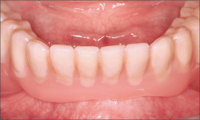
Fig 1 Existing mandibular prosthesis, anterior view.
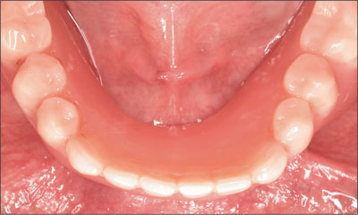
Fig 2 Existing mandibular prosthesis, occlusal view.
He was satisfied with the performance and functional characteristics of the maxillary prosthesis. A detailed evaluation of the vertical dimension of occlusion and the interocclusal rest space revealed that his existing pros-theses were satisfactory. The maxillary and mandibular edentulous residual alveolar ridges were atrophic (Figs 3 and 4), although each residual ridge displayed adequate regions of attached keratinized mucosa.
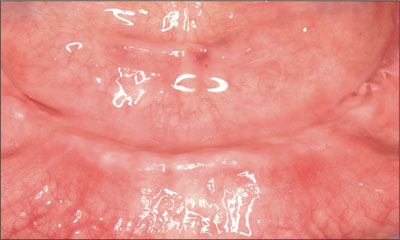
Fig 3 Atrophic mandible edentulous ridge.
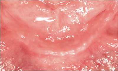
Fig 4 Atrophic mandibular edentulous ridge.
The patient understood the need for the extraction of the remaining diseased maxillary teeth. He expressed a strong desire to maintain his existing prostheses if practical. In addition, he requested that improvements be made to the functional characteristics of his mandibular denture, while maintaining the prosthesis, at minimal expense.
Subsequent to the detailed consideration of all the treatment options, the patient accepted the following treatment plan. The remaining maxillary teeth were to be removed as soon as possible, and the existing maxillary denture lined initially with tissue conditioner, prior to permanent rebasing. Treatment for the mandibular arch included the surgical placement of two narrow-connection, reduced-diameter bone-level implants in the canine regions. Upon successful healing, the implants were planned to support Locator abutments. The patient’s existing complete mandibular prosthesis would then be re-based and retrofitted to incorporate Locator attachments, improving the support, stability, and retention of the prosthesis while maintaining the existing vertical and esthetic relationships. This treatment plan satisfied the patient’s desire to utilize his existing prostheses and would establish oral health.
The existing mandibular denture was duplicated in clear autopolymerizing acrylic resin (PalaXpress Clear, Heraeus Kulzer, Hanau, Germany). The duplicate denture was reduced in the intraforaminal region, between the first premolars, and metal indicator balls were positioned in the preferred canine regions (Fig 5). A panoramic radiograph was obtained, confirming adequate bone height to support dental implants (Fig 6).
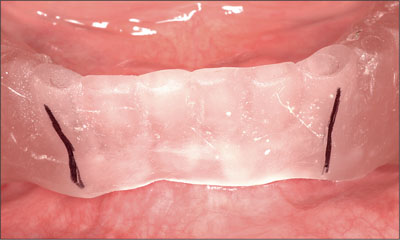
Fig 5 Reduced duplicate denture with metal indicator balls.
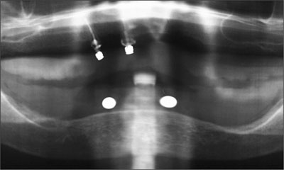
Fig 6 Diagnostic panoramic radiograph showing adequate bone height.
Two narrow-connection reduced-diameter dental implants were planned for several reasons including the presence of a narrow residual ridge and a small band of attached keratinized tissue (Fig 7).
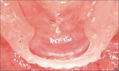
Fig 7 Narrow residual ridge and attached keratinized tissue.
A conservative mid-crestal incision was made under local anesthesia. The residual ridge was exposed through the elevation of full-thickness flaps with no releasing incisions. The knife-edge crestal region was reduced using surgical rongeurs, and the harvested bone was preserved in anticipation of the need for local bone augmentation subsequent to implant placement.
The desired implant sites were identified using a surgical template (Fig 8). Osteotomies were prepared without complication (Fig 9), and the two implants positioned (Straumann Bone Level NC SLActive, Ø 3.3 mm, length 10 mm; Figs 10 and 11). The inclination and position of the implants were confirmed prior to the removal of the implant-positioning mount (Fig 12).
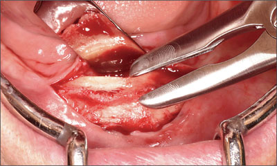
Fig 8 Identifying the surgical sites.
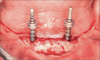
Fig 9 Prepared osteotomies.
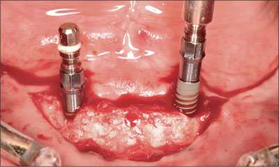
Fig 10 First Straumann NC SLActive implant (Ø 3.3 mm, length 10 mm).
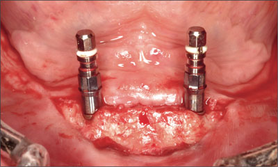
Fig 11 Second Straumann NC SLActive implant (Ø 3.3 mm, length 10 mm).
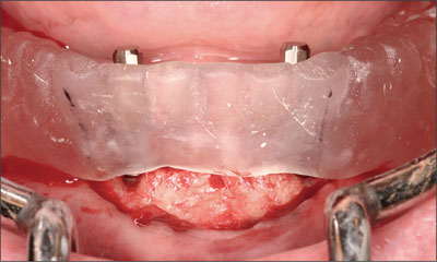
Fig 12 Confirming inclination and position of the implants.
Cover screws were positioned, and minor areas of SLActive surface exposure on the facial aspects of the implants were augmented using the bone chips previously retained and covered with a periosteal cover. Each implant was submerged at wound closure. The patient’s existing mandibular prosthesis was modified to provide relief in the region of the implants and the surgical site. It was lined with tissue conditioner (Visco-Gel, Dentsply DeTrey, Konstanz, Germany) and adjusted as indicated, and the patient was released.
The implants were allowed to heal without disturbance for a period of 10 weeks (Fig 13). Localized access was made to the implants under local anesthesia. The cover screws were removed without incident and replaced with narrow-connection healing abutments (Fig 14). Each implant was deemed stable. The existing denture lining was removed and replaced to register the healed soft-tissue architecture and the healing abutments.
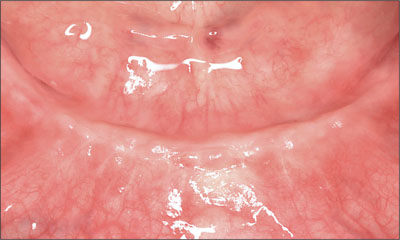
Fig 13 Result after 10 weeks of healing.
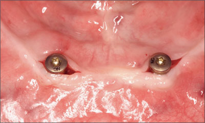
Fig 14 Implants and healing abutments following reentry.
The surgical site was allowed an additional 4 weeks of healing (Fig 15). The healing abutments were then removed (Fig 16) and the depth of the mucosa assessed. Locator abutments were then chosen to allow supramucosal positioning of the attachments (Figs 17 and 18). The vertical bulk of the denture was considered non-contributory with regard to abutment height. The supramucosal position of the Locator abutments ensured access for continued home maintenance and facilitated self-alignment of the denture on insertion.
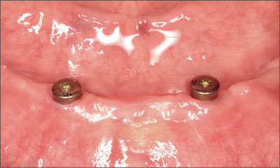
Fig 15 After another 4 weeks of healing (14 weeks total).
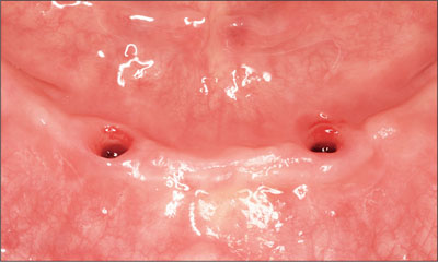
Fig 16 Situation following removal of the healing abutments.
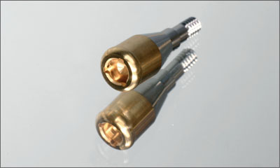
Fig 17 Locator abutment for a narrow-connection bone-level implant.
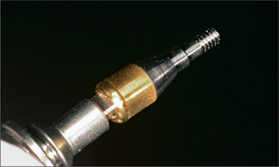
Fig 18 Locator abutment close-up.
Each abutment was positioned and torqued to the recommended 35 Ncm without complaint (Figs 19 and 20). Teflon spacers and titanium caps with low-density polyethylene (LDPE) transfer units were positioned (Figs 21 and 22). Subsequent to the removal of the existing lining, the denture base was relieved with a disclosing medium to ensure accurate tissue adaptation with no contact in the regions of the abutments and attachments (Fig 23). A final rebasing impression was then taken using a poly-ether impression material (Impregum, ESPE, Seefeld, Germany) with a corresponding adhesive (Polyether adhesive, ESPE), using the mandibular denture as an impression tray (Figs 24 and 25).
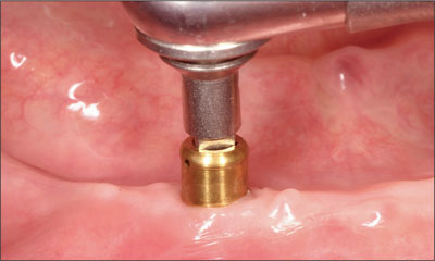
Fig 19 Tighenting the abutment to 35 Ncm.
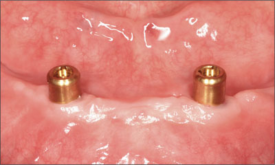
Fig 20 The two abutments protruding past the soft tissue.
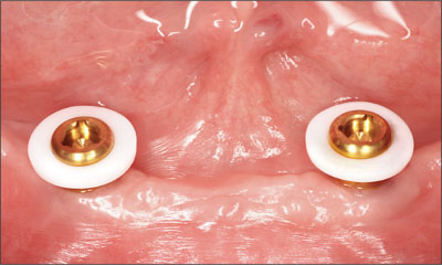
Fig 21 Teflon spacers in place.
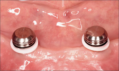
Fig 22 Titanium caps with LDPE transfer units connected.
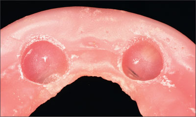
Fig 23 Relief of the denture base.
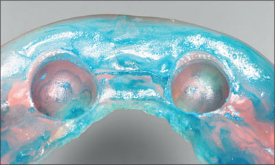
Fig 24 Preparing for the final rebasing impression.
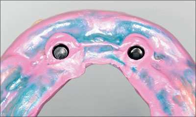
Fig 25 Final rebasing impression.
The rebasing and attachment indexing were planned to facilitate the return of the mandibular denture at the same appointment. Locator abutment analogs were positioned in the impression (Figs 26 and 27), and a master cast was poured in improved dental stone (Jade Stone, Whip Mix Corporation, Louisville, KY, USA; Fig 28).
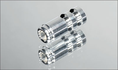
Fig 26 Locator analog.
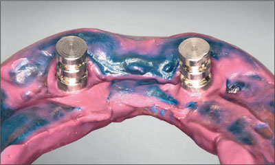
Fig 27 Locator analogs in the rebasing impression.
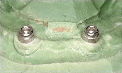
Fig 28 Master cast.
Titanium caps were then positioned onto the abutment analogs, sandblasted, and primed (Alloy Primer, Kuraray, Tokyo, Japan) to improve the seal and retention to the denture base. The denture base was then rebased (PalaXpress, Heraeus Kulzer, Hanau, Germany), incorporating the Locator attachments, and finished (Figs 29 and 30).
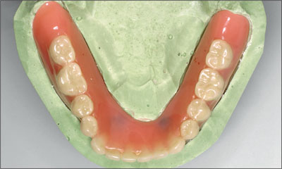
Fig 29 Maxillary denture, occlusal view.
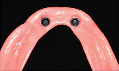
Fig 30 Tissue side of the denture with Locator titanium caps incorporated.
The denture was then verified for tissue adaptation and the alignment of the attachments to the abutments (Fig 31). The occlusal and vertical relationships were verified with minor adjustments made through a clinical remounting process. The patient’s ability to remove the prosthesis without difficulty was confirmed, and post-treatment oral hygiene instruction was provided.
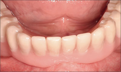
Fig 31 Verifying the seating of the denture.
Follow-up assessments were undertaken after 48 hours and 1 week. Minor adjustments to the denture base were made as indicated. At the 1-week follow-up, the black processing blanks were removed (Fig 32) and replaced with the blue (6.7 N) attachments using a locator core tool (Figs 33 to 37).
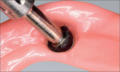
Fig 32 Removing the black processing blank.
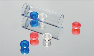
Fig 33 Color-coded attachments.
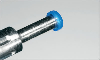
Fig 34 A blue attachment was selected.
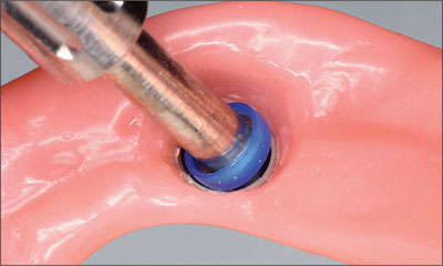
Fig 35 Integrating the blue attachment into the denture.
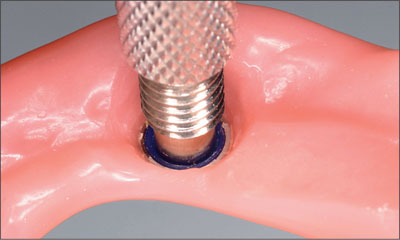
Fig 36 Locator core tool used to secure the blue attachment in place.
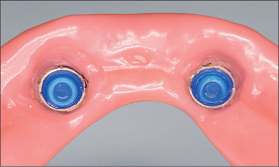
Fig 37 Both Locator attachments in their final positions.
Further reevaluation appointments took place after 6 and 24 weeks and after 12 months. The patient continues to report complete satisfaction with the prosthesis with regard to function, comfort, and esthetic outcome. No clinical or radiographic concerns were noted (Figs 38 and 39).
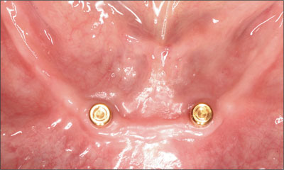
Fig 38 Clinical situation at follow-up.
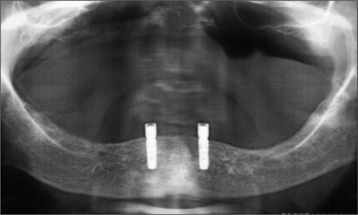
Fig 39 Panoramic radiograph at follow-up.
This conservative and efficient treatment should be considered for patients with appropriate indications.
Acknowledgments
Laboratory Procedures
Frank Siebert, Master Dental Technician,
Rübeling + Klar Dental-Labor – Halle (Saale), Germany
6.1.3 Conventional Loading of Two Implants in the Mandible and Final Restoration with a Bar-Supported RDP
H.J.A. Meijer
A 63-year-old female patient was referred to the University Medical Center in Groningen, Netherlands, for dental implant treatment. The patient had been edentulous in the upper jaw for 20 years. The remaining teeth in the lower jar had been removed two years before the consultation. The patient was wearing her first maxillary denture and her second mandibular denture; the latter was 1 year old at the time. The conventional upper denture had functioned satisfactorily for many years, but the patient complained about reduced stability and insufficient retention of her lower conventional denture. Her medical history revealed no significant findings. The intraoral examination revealed minor resorption of the maxillary alveolar process and extreme resorption of the mandibular alveolar process. Retention and stability of the maxillary denture were normal, while the mandibular denture exhibited no stability or retention at all, and the occlusion was balanced without anterior contact. Radiographic diagnosis included a rotational panoramic radiograph and a lateral cephalometric radiograph (Figs 1 and 2).
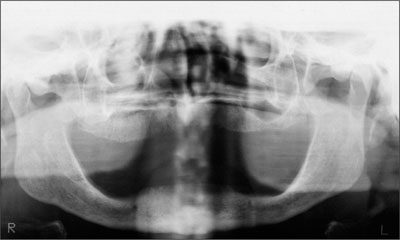
Fig 1 Baseline rotational panoramic radiograph.
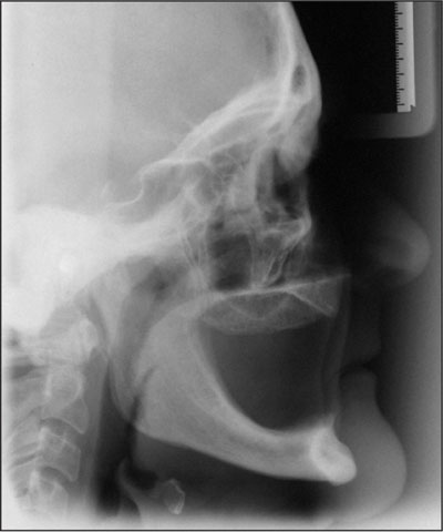
Fig 2 Baseline lateral cephalometric radiograph.
The height of the mandible was 20 mm with a slight knife-edge ridge, as measured in the symphysis region on the lateral cephalometric radiograph (Cawood and Howell class IV). The treatment plan proposed to the patient included two endosseous implants in the interforaminal region of the mandible, a mandibular overdenture supported by a bar attachment system, and a new conventional denture in the maxilla. The patient was informed of the risks and gave her written informed consent.
Procedure
Two Straumann Standard dental implants (Ø 4.1 mm, length 14 mm) were inserted under local anesthesia after the removal of the bony knife-edge ridge aspect. The implants were inserted in the canine region of the mandible, each about 1 cm away from the midline. The procedure was carried out in a one-stage technique. Postoperative analgesics and 0.2% chlorhexidine digluconate mouth rinses were prescribed, but no antibiotics. The patient was not allowed to wear her mandibular denture during the first week after surgery, after which the sutures were removed. A soft liner was applied after selectively relieving the mandibular denture at the implant site. The patient also received oral hygiene instructions. Prosthetic procedures started after a 6-week healing period. The implants were stable and surrounded by healthy peri-implant mucosa (Fig 3).
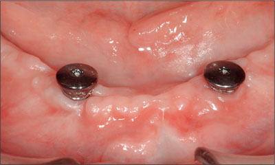
Fig 3 Two Straumann Standard implants at the end of the 6-week healing period.
The preliminary impression was taken using stock metal trays and alginate (Fig 4). Custom composite trays were fabricated with openings for screw-retained synOcta impression posts. The impression posts were fixed at the implant level (Fig 5).
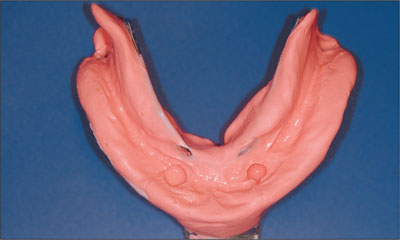
Fig 4 Preliminary impression for manufacturing the custom tray.
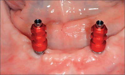
Fig 5 The impression posts mounted on implants.
The tray was placed over the impression posts, and any contact between the post and the tray was avoided to allow the tray to rest firmly on the denture-bearing mucosa. The screw of the post was positioned above the opening of the tray (Fig 6).
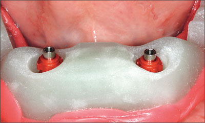
Fig 6 Custom impression tray with posts.
The final impression was taken in a hard polyether material. The impression material around the posts was administered by a syringe. The tray was filled and placed on the alveolar process. During setting, the screws had to remain uncovered to facilitate removal of the impression (Fig 7).
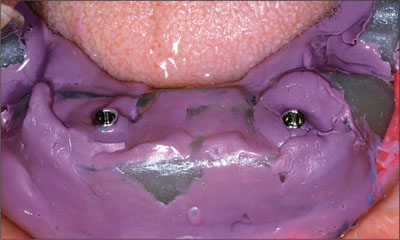
Fig 7 Impression taken with a stif polyether impression material. The screws of the impression posts are visible.
The posts were connected to implant analogs in the impression tray, and the master cast was poured (Figs 8 and 9).
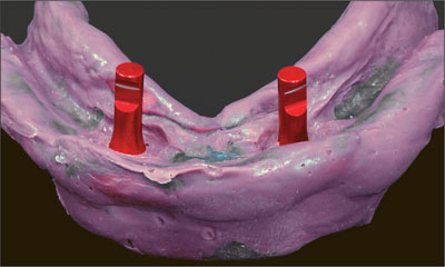
Fig 8 Implant analogs connected to the impression posts.
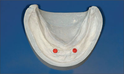
Fig 9 Plaster cast with implant analogs.
In this way, the implant location and the denture-bearing area were reproduced. Before determining the vertical and horizontal dimensions of the new dentures, the bar and the acrylic base of the overdenture were fabricated. A stable and well-retained base made it easier to record the interarch relationship. SynOcta abutments were chosen as connections between implants and titanium copings. An ovoid titanium bar was connected to the titanium copings, and a gold clip was selected (Fig 10).
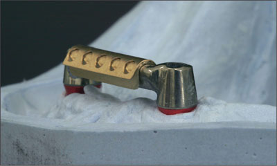
Fig 10 Bar with selected length of clip on the master cast.
Requirements for placing the bar include parallelism with the line between the temporomandibular joints, accessibility for oral hygiene, no encroachment on the tongue space, and accommodation of the positions of the artificial teeth. The acrylic denture base was poured and the clip incorporated (Figs 11 and 12).
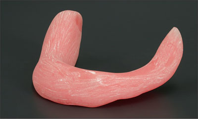
Fig 11 Final acrylic base of the overdenture.
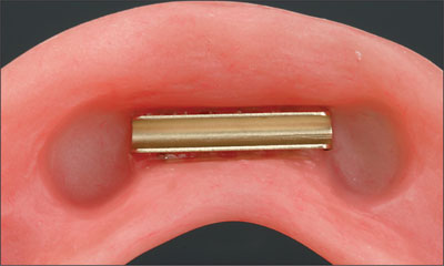
Fig 12 The clip in the denture base.
An occlusal wax rim was attached to the denture base (Fig 13).
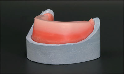
Fig 13 Occlusion wax rim on the denture base.
The synOcta abutments were connected to the implants in the patient’s mouth, and the bar was screwed on the abutments (Figs 14 and 15).
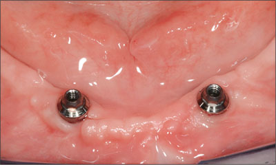
Fig 14 synOcta abutments connected to the implants.
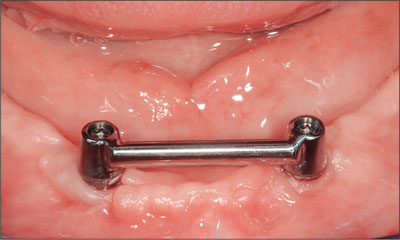
Fig 15 Titanium bar connected to the abutments.
To check the seating of the clip on the bar, a two-component silicone-based disclosing material was inserted in the area of the clip and placed on the bar in the mouth (Fig 16).
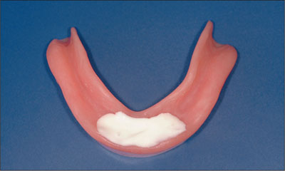
Fig 16 Silicone-based disclosing material was inserted in the area of the clip.
After the setting of the disclosing material, the denture base was removed. There was to be a connection between the clip and the bar but no connection between the bar and the acrylic, which was verified (Fig 17).
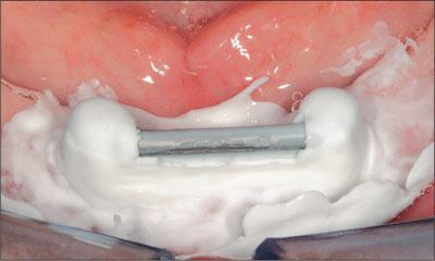
Fig 17 Checking the connection.
If a connection between the bar and the acrylic had existed, the area would have had to be relieved and the seating rechecked.
Occlusal wax rims on bases were used to determine the vertical dimension and the level of the occlusal plane and to record the maxillomandibular relation (Figs 18 and 19).
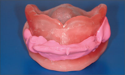
Fig 18 Anterior view of the occlusal wax rim.
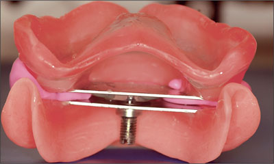
Fig 19 Dorsal view of the maxillomandibular relationship.
After completion of the tooth set-up, the trial dentures in wax were tried in intraorally and corrections were made. The lingualized occlusion concept with bilateral balanced guidance and ceramic teeth was used (Figs 20 and 21).
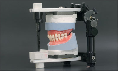
Fig 20 Tooth set-up in the articulator.
Fig 21 Partial view of the tooth set-up with occlusion.
The tooth set-up was approved by both the dentist and the patient, and the conventional upper denture and mandibular overdenture could be finished in the laboratory (Fig 22).
Fig 22 The finished prostheses on the master casts mounted in the articulator.
At the delivery of the prostheses, the synOcta abutments were placed and tightened to 35 Ncm with a torque controller. The bar was connected and the occlusal screws were tightened to 15 Ncm. After insertion, the adaptation of the base was examined with disclosing material. Once the adaptation had been checked, occlusion and articulation were examined. If necessary, the retention force of the clip can be adjusted at this stage.
The patient was taught to remove the overdenture and to clean the prosthesis and bar. A few days after delivery, the first check-up was performed, and peri-implant radiographs were taken to record peri-implant bone levels at the outset of the functional period (Figs 23 and 24).
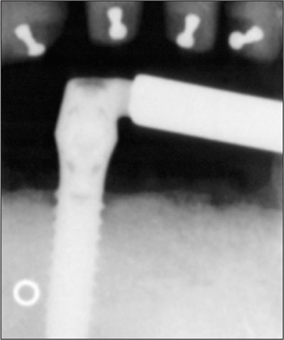
Fig 23 Intraoral radiograph at overdenture delivery: right implant.
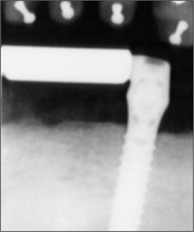
Fig 24 Intraoral radiograph at overdenture delivery: left implant.
Follow-up
A regular yearly recall system was applied. The status of the alveolar process was checked intraorally together with peri-implant items such as plaque and calculus accumulation, mucosa, sulcus depth, and bleeding. The evaluation of the prosthesis included the fit of the denture base, occlusion and articulation, fracture of denture base or teeth, and clip loosening or fracture. At the 4-year follow-up, the patient presented a satisfactory clinical situation and a favorable peri-implant bone level (Figs 25 to 26).
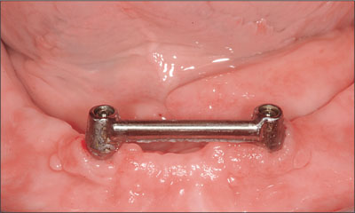
Fig 25 Bar after 4 years in function.
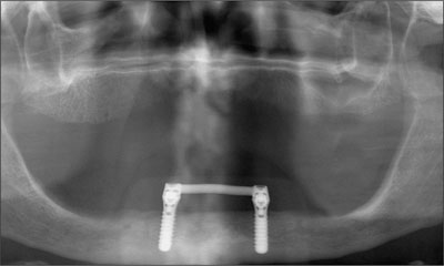
Fig 26 Rotational panoramic radiograph after 4 years in function.
No complications had occurred during these 4 years and the patient was still very satisfied with the improved function of the mandibular denture.
Acknowledgments
Surgical Procedures
Prof. G.M. Raghoebar – Groningen, Netherlands
Laboratory Procedures
Gerrit van Dijk – Groningen, Netherlands
6.1.4 Conventional Loading of Six Implants in the Mandible and Final Restoration with a Full-Arch Metal-Ceramic FDP
A. Boeckler, D. Morton
A 68-year-old, completely edentulous male patient presented for evaluation and treatment options. He reported excellent general health and was taking no regular medication. He had been edentulous for approximately 12 years, having lost his teeth to periodontal disease and dental caries.
The patient’s chief complaint was incompetent function. His secondary concerns included his appearance (Fig 1) and the desire for a predictable outcome.
Fig 1 Patient’s lip line at baseline.
He attributed his reduced functional capacity to his lower complete denture, which he described as poor. He was particularly concerned with the denture’s instability and poor fit. In general terms, he was satisfied with the maxillary complete prosthesis. The maxillary prosthesis was characterized by adequate retention, stability, and support, although the fit was considered less than ideal (Fig 2).
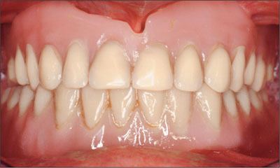
Fig 2 Intraoral baseline situation.
The intraoral evaluation revealed moderately resorbed maxillary and mandibular arches. All tissues appeared to be healthy, and there was no evidence of inflammation or infection. The residual mandibular ridge appeared to be adequate with regard to regions of attached, keratinized tissue (Fig 3).
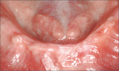
Fig 3 Adequate residual mandibular ridge with regions of attached, keratinized tissue.
The existing prostheses displayed wear and both occlusal and aesthetic deterioration. An assessment of rest space revealed inadequate restoration of occlusal vertical dimensions. Radiographic evaluation confirmed the absence of underlying pathologies.
The patient was provided with several treatment alternatives:
Option I. Removable complete prostheses in both arches.
Option II. Removable complete maxillary prosthesis in conjunction with a removable complete implant-supported mandibular prosthesis.
Option III. Removable complete maxillary prosthesis in conjunction with a fixed implant-supported complete mandibular prosthesis.
Subsequent to detailed discussions regarding the advantages and disadvantages of each option, the patient consented to option III, a removable complete maxillary prosthesis in conjunction with a fixed complete implant-assisted mandibular prosthesis.
The patient’s existing mandibular prosthesis was duplicated in clear auto-polymerizing polymethyl methacrylate (PalaXpress Clear, Heraeus Kulzer, Hanau, Germany). Six metal balls (Ø 5 mm) were positioned into the duplicate denture in the desired implant positions. A panoramic radiograph was obtained (Fig 4), confirming adequate height of bone in the region between the mental foramina.
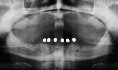
Fig 4 Metal balls planned implant positions on the radiograph.
The metal balls were then replaced with drill sleeves to form the surgical template (Fig 5).
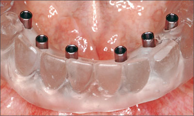
Fig 5 Surgical template.
Six dental implants (Straumann RN Standard, Ø 4.1 mm, length 12 mm) were positioned under local anesthetic, and transmucosal healing abutments were placed (Ø4.8 mm, height 1 mm). A postsurgical radiograph was obtained (Fig6).
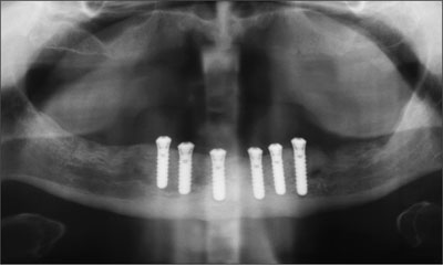
Fig 6 Postsurgical radiograph.
The implants were allowed to heal for a period of 3 months. The healing abutments were removed without incident (Fig 7). Preliminary impressions were made of the mandible and the maxillary arch in irreversible hydrocolloid (Tetrachrom, Kaniedenta, Herford, Germany). A conventional customized impression tray with perforations for impression caps was fabricated for the mandible (DC Tray, Dental Central, Trittau, Germany). SynOcta impression caps were positioned (Fig 8). An open-tray (pickup) impression was made in polyether impression material (Impregum, 3M Espe, Seefeld, Germany; Fig 9) and a preliminary jaw relation registration was performed. The cast for the mandible was fabricated in type IV dental stone (Unibase 300, dentona, Dortmund, Germany). Impression copings were repositioned on the mandibular cast and a framework fitting around the impression copings were fabricated from Co-Cr-alloy (Triloy, Dentaurum, Ispringen, Germany; Fig 10).
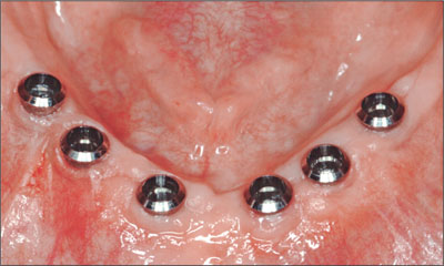
Fig 7 Implants after removing the healing abutments.
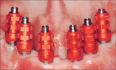
Fig 8 synOcta impression posts connected.
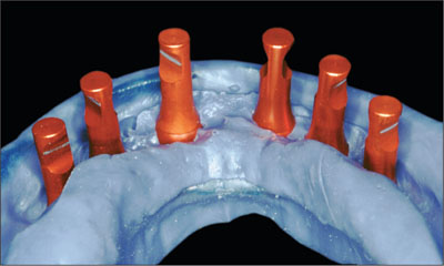
Fig 9 Polyether impression.
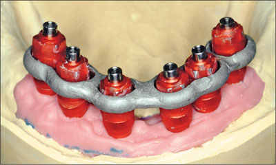
Fig 10 CoCr fitting around the impression copings.
After provisional articulation of the casts, acrylic-resin baseplates were fabricated for each arch (DC Tray, Dental Central). A window was created in the mandibular baseplate to facilitate picking up of the acrylic resin-impression analog matrix in the final impression (Fig 11)
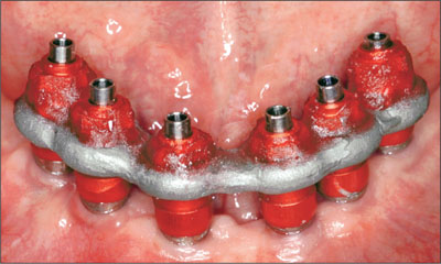
Fig 11 Ready for picking up the matrix in the final impression.
To obtain passivity for the future restoration, the impression copings were positioned and intraorally linked to the customized Co-Cr-framework with autopolymerizing poly-methyl methacrylate (Pattern Resin, GC, Tokyo; Fig 12).
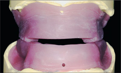
Fig 12 Acrylic resin baseplates with rims for jaw relation record.
Each baseplate with acrylic rim was then utilized as a custom tray (Fig 13), facilitating the making of the final impression for each arch using polyether impression material (Impregum, 3M Espe) and the recording of the maxillomandibular relationship (jaw relation records, Fig 14). A facebow registration was obtained (Artex, Amann Girrbach, Pforzheim, Germany), and the final casts (Unibase 300, dentona) articulated on a semiadjustable articulator.
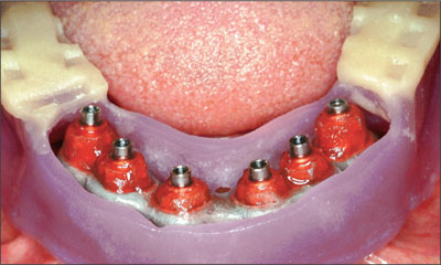
Fig 13 Baseplate used as a custom tray.
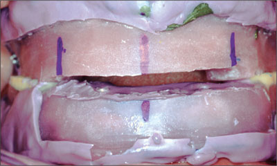
Fig 14 Jaw relation records with matrices encased in acrylic resin baseplate.
Teeth (Vitapan anteriors and posteriors, cuspiform, VITA Zahnfabrik, Bad Säckingen, Germany) were positioned on the maxillary wax rim (supported by the baseplate), and the mandibular matrix was retained by plastic bite registration aids according to the proposed occlusal vertical dimension and esthetic arrangement (Fig 15).
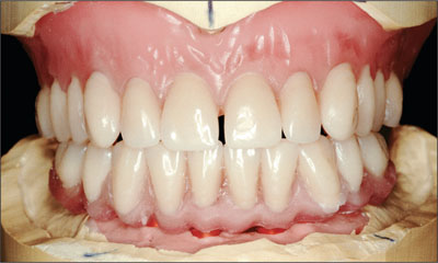
Fig 15 Tooth set-ups.
The position of the maxillary teeth in particular was individualized to satisfy the patient’s esthetic demands (Fig 16). The patient’s satisfaction with the proposed tooth position was confirmed at try-in (Fig 17).
Fig 16 Individualized positions of the maxillary teeth.
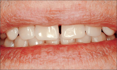
Fig 17 Tooth set-up at try-in.
Upon verification and acceptance of the tooth positions, a polyvinyl siloxane putty matrix (alphasil perfect, Omicron, Lindlar, Germany) was fabricated to relate the mandibular tooth position to the mandibular master cast (Fig 18).
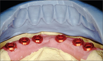
Fig 18 Index for recording the relationships between the mandibular tooth position and the mandibular master cast.
Abutments (synOcta 1.5) were then positioned into the implant analogs (Fig 19), and a full-contour wax-up (Finocrown, Fino, Bad Bocklet, Germany) for the proposed metal ceramic fixed dental prosthesis was made.
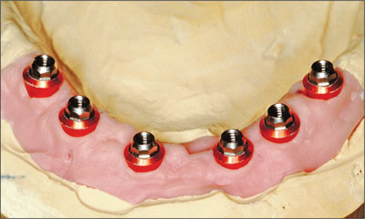
Fig 19 Abutments connected to the implant analogs.
The pattern was then cut back to provide the ideal ceramic proportions using the silicone matrix (Figs 20 and 21).
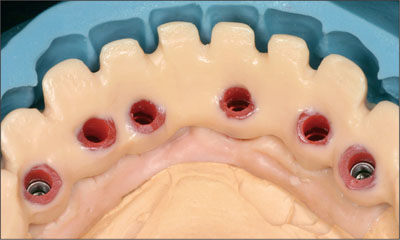
Fig 20 Cutbacks, lingual view.
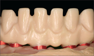
Fig 21 Cutbacks, anterior view.
The framework was then cast in high-precious alloy (DeguDent U, DeguDent, Hanau, Germany) and verified for fit on the master cast, then finished (Figs 22 and 23).
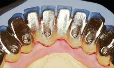
Fig 22 Cast framework, lingual view.
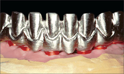
Fig 23 Cast framework, anterior view.
The framework’s passivity and contours were then evaluated orally and considered satisfactory (Fig 24).
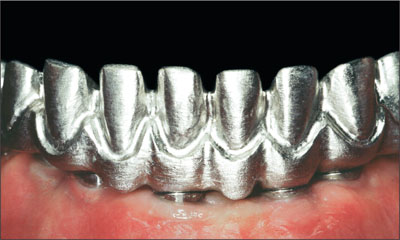
Fig 24 Framework seated passively and presenting adequate contours.
The metal-ceramic mandibular fixed dental prosthesis was finalized along with the final maxillary tooth position (Art i-motion, Debomed, Nienhagen, Germany; Fig. 25).
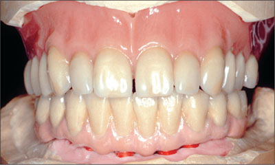
Fig 25 Finalized mandibular FDP and final maxillary tooth positions.
The final esthetic contours of both prostheses were modified and adjusted to satisfy the patient’s demands (Figs 26 and 27).
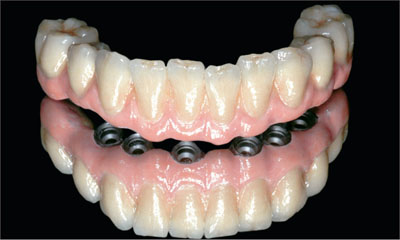
Fig 26 Mandibular restoration after slight modifications.
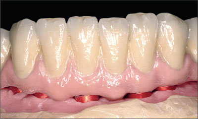
Fig 27 Mandibular restoration, detail.
Once confirmed and accepted, the final positioning of the maxillary denture teeth was undertaken, and it was processed in polymerized polymethyl methacrylate (Aesthetic autopolymer, Candulor, Wangen, Switzerland).
At delivery, synOcta 1.5 abutments were positioned in each implant and tightened to a torque of 35 Ncm (Fig 28).
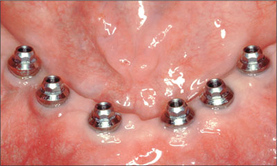
Fig 28 synOcta 1.5 abutments in situ.
The definitive metal-ceramic mandibular fixed dental prosthesis was positioned and verified for clinical passivity and esthetic satisfaction (Figs 29 and 30).
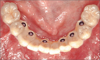
Fig 29 Mandibular FDP, occlusal view.
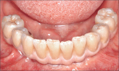
Fig 30 Mandibular FDP, anterior view.
Access for hygiene maintenance was also confirmed, and the patient was provided with comprehensive post-delivery oral-hygiene instructions (Fig 31).
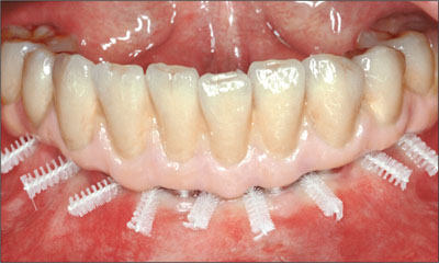
Fig 31 Possible insertion paths for interdental brushes.
The maxillary complete prosthesis was adjusted as required for adaptation and extension (Pressure Indicator Paste, Keystone Europe, Wijchen, Netherlands). An interocclusal rearticulation record was obtained, and minor occlusal adjustments were made on the articulator. The maxillary complete prosthesis was then delivered to the patient (Fig 32). The patient was satisfied with the final esthetic and functional outcome (Figs 33 and 34).
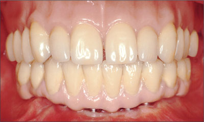
Fig 32 The completed restorations in situ.
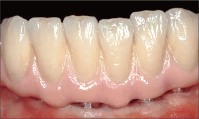
Fig 33 Detail of the completed mandibular FDP.
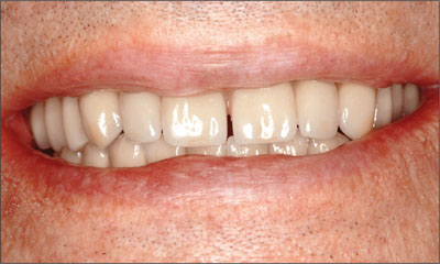
Fig 34 Patient’s lip line after delivery.
The patient has had regular yearly follow-ups subsequent to treatment. After 5 years of service, the functional and esthetic satisfaction of the patient has been maintained, and no evidence of radiographic abnormalities has been noted (Figs 35 to 37).
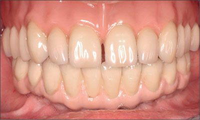
Fig 35 At the 5-year follow-up, anterior view.
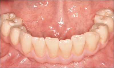
Fig 36 Mandibular FDP at the 5-year follow-up.
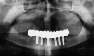
Fig 37 Radiograph at the 5-year follow-up.
Acknowledgments
Surgical Procedures
Johannes Schubert, Prof. Dr. Dr., Department of Oral and Maxillofacial Plastic Surgery, Martin Luther-University
Hallo-Wittenberg – Halle (Saale), Germany
Laboratory Procedures
Andreas Senke, Master Dental Technician, Zahntechnik Xental – Großkugel, Germany
6.1.5 Transition from a “irrational to treat” Maxillary Dentition to a Full-Arch Segmented FDP by Early Loading of Eight Implants Placed Using the Staged Approach
L. Cordaro
The staged approach permits the transition from an “irrational to treat”dentition to a full arch implant supported restoration without any need to use a removable provisional prosthesis or to apply the immediate-placement and immediate-loading techniques.
A failing dentition is the usual indication for a staged treatment.
On the other hand, the dentition should still contain many residual teeth, but with few or none of them being suitable for use as definitive abutments for a full-arch fixed restoration. This situation is usually the result of advanced periodontal disease or of the failure of an extensive fixed prosthesis.
The staged approach usually includes the following treatment steps (Table 1):
| Stage | Treatment | Timing, maxilla (weeks) | Timing, mandible (weeks) |
| 1 | Initial periodontal treatment | – | – |
| 2 | Tooth extraction and preparation of residual teeth as abutments; FDP removal if required | 0 | 0 |
| 3 | First-stage implant insertion | 3–6 | 3–6 |
| 4 | Second-stage implant insertion (immediately after extraction) and loading of the first-stage implants | 11–14 | 6–9 |
| 5 | Loading of the second-stage implants; completion of extractions | 19–22 | 12–18 |
| 6 | Standard prosthetic phase | 23–26 | 16–22 |
-
Periodontal treatment. Active periodontal pockets must be eliminated before the prosthetic treatment is started. This is crucial because proper soft-tissue healing and post-extraction implant insertion cannot be safely accomplished in the presence of active periodontal lesions (Fig 1a).
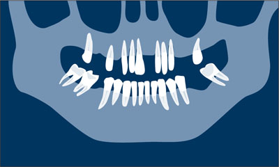
Fig 1a Periodontal treatment.
-
Tooth extraction and insertion of the first provisional. A provisional cross-arch FDP to be relined in the mouth is prepared using standard techniques. Strategic extraction of some teeth is performed and the remaining teeth are prepared as abutments for the provisional acrylic-reinforced restoration. At this stage, the ovate-pontic technique may be used for soft-tissue conditioning in order to maintain the facial prominence of the tissues around the remaining abutments. If this is the case, the failing FDP is removed now. The teeth to be kept for the first provisional phase should be strategically chosen to maintain support for the provisional restoration. The clinician should also consider the quality and quantity of the bone at the future implant site to guarantee the primary stability of adequately dimensioned implants (Fig 1b).
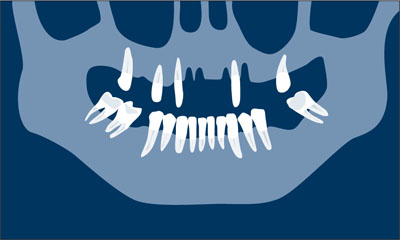
Fig 1b Tooth extraction and insertion of the first provisional.
-
First-stage implant insertion. After soft-tissue healing (3 to 6 weeks), implants are inserted in the extraction sockets or in the edentulous spaces that were present at patient presentation. Flap elevation should be kept to a minimum. After implant surgery, the first provisional can be redelivered after minimal adjustments. The number and position of the implants are determined depending on the available support by the natural abutments that are temporarily kept in order to safely support the first provisional FDP. At least four implants are inserted at this time (Fig 1c).
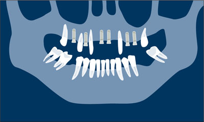
Fig 1c First-stage implant insertion.
-
Loading of the first-stage implants and second-stage implant insertion. After normal healing—6 weeks in the lower jaw, and 8 weeks in the maxilla for SLA (sandblasted, large-grit, acid-etched) surface implants (Straumann AG, Basel, Switzerland)—a second surgical step is performed. During the same session, the first-stage implants are connected to provisional abutments, other teeth are extracted, and immediate post-extraction implants are placed where needed. Some residual natural abutments may be still kept in place to support a second provisional FDP which will have mixed support. This procedure prevents implant overloading (Fig 1d).
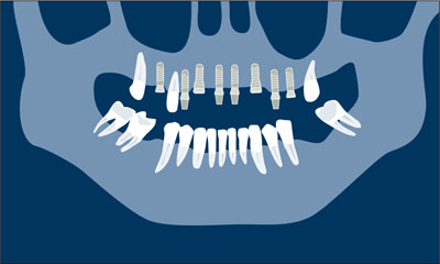
Fig 1d Loading of the first-stage implants and second-stage implant insertion.
-
Loading of the second-stage implants. After healing of the newly placed implants, the remaining teeth are extracted. Abutments are connected, and the patient is ready for the last treatment step (Fig 1e).
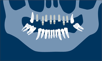
Fig 1e Loading of the second-stage implants.
-
Definitive prosthetic phase. Final soft-tissue conditioning is performed and impressions are taken for the final restoration. The definitive abutments may differ in size and type from the ones used for the provisional. A screw-retained or cemented design may be used for either the provisional or the definitive prosthesis (Fig 1f ).
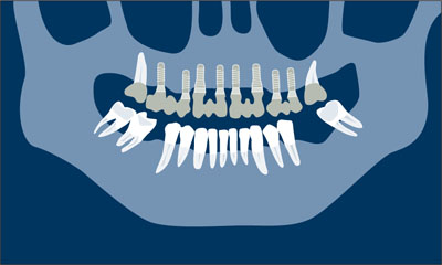
Fig 1f Definitive prosthetic phase.
The following clinical case illustrates this approach.
Clinical Situation
A female patient in good general health, a smoker (20 cigarettes/day) with poor oral hygiene, complained of tooth mobility and difficulty in chewing.
The patient’s primary desire was to receive a “definitive and reliable fixed restoration.” She was also concerned about her long and flaring anteriors, but did not want to have the missing mandibular teeth restored.
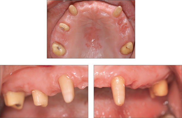
At presentation, the patient was wearing a removable partial prosthesis to replace her left central incisor. Her upper canines exhibited class III mobility and had less than one-third of their bony support left (Figs 2 to 6). Teeth 16, 13, 12, 22, 23, and 25 had deep pockets (more than 6 mm).
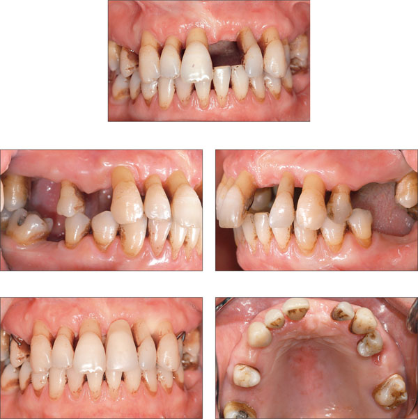
Figs 2 to 6 Clinical baseline situation: Advanced periodontal disease, flaring, and hypereruption of the anteriors. The upper incisors and canines exhibit class III mobility.
The full-mouth radiographic survey (Fig 7) confirmed the diagnosis of advanced periodontal disease. In the upper arch, the right first molar, the remaining incisors, and the left second premolar had to be extracted (Table 2)
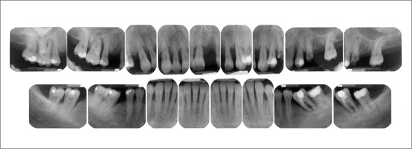
Fig 7 Maxillary radiographic survey. Advanced periodontal bone loss at teeth 16, 13, 12, and 11. The furcation involvement of tooth 24 was discovered clinically. Recurrent caries had been present at tooth 25, extracted by the referring dentist before the first examination.
| Tooth | 17 | 16 | 15 | 14 | 13 | 12 | 11 | 21 | 22 | 23 | 24 | 25 | 26 | 27 |
| Questionable | x | x | x | x | x | x | x | |||||||
| Reliable | x | x | x | x |
The patient was told that teeth 17, 15, 13, 23, 24, and 27 might support a 14-unit full-arch restoration. The canines exhibited class III mobility and deep pockets that might be treated with periodontal surgery. A conservative approach will include periodontal surgery and a restoration supported by four reliable and two questionable abutments (the upper cuspids).
After considerable discussion, the following treatment plan is accepted by the patient: All maxillary teeth except the second molars were to be extracted and the patient were to be provided with an implant-supported full-arch restoration.
To facilitate a fixed provisional throughout the treatment, a staged approach was proposed.
This approach is based on the concept of selective extraction of some of the remaining teeth, maintaining others and eventually preparing them as abutments for a fixed provisional restoration. Implants may be placed in the edentulous spaces and allowed to heal without loading.
Once osseointegration has occurred, implants may be loaded with the fixed provisional restoration. Second-stage implant insertion and the remaining extractions can then be performed and the final prosthetic phases implemented.
Treatment Steps
The initial periodontal treatment was followed by the first surgical and prosthetic phases. The maxillary incisors, the left premolars, and the right first molar were extracted. The remaining maxillary teeth were prepared as abutments to support a provisional acrylic full-arch restoration (Figs 8 and 9). Table 3 lists the teeth to be extracted during the first stage.
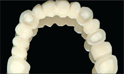
Fig 8 The provisional acrylic restoration is ready for relining.
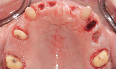
Fig 9 Occlusal view of the prepared teeth and the empty alveolar sockets before insertion of the provisional restoration.
At this stage, two second molars, two canines and the right second premolar supported the provisional restoration.
| Tooth | 17 | 16 | 15 | 14 | 13 | 12 | 11 | 21 | 22 | 23 | 24 | 25 | 26 | 27 |
| Questionable | x | x | x | x | x | x | x | |||||||
| Reliable | x | x | x | x | ||||||||||
| First extractions | x | x | x | x | x | x |
The patient was ready for implant insertion 6 weeks after the extractions. Oral hygiene had improved, and the mobility of the canines had decreased, probably because of the cross-arch stabilization provided by the provisional restoration (Figs 10 to 12). The extraction sockets were completely filled with soft tissue at this stage. The periodontal tissues had improved, showing no signs of active inflammatory lesions. The early post-extraction implant insertion protocol was used (type 2 according to the 2004 ITI Consensus).
Figs 10 to 12 Clinical situation 6 weeks after the extractions.
The panoramic radiograph showed an ideal bone situation regarding mesiodistal and vertical dimensions, but the extraction sockets exhibited minimal bone fill.
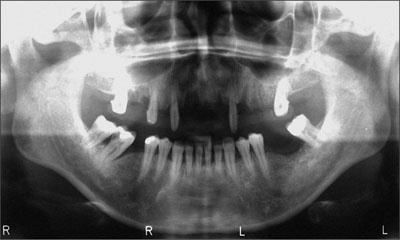
Fig 13 Panoramic radiograph before implant insertion (first stage). The reduced bony support of the premolars is clearly visible, and the extraction sockets do not exhibit complete bone fill.
According to the definitive treatment plan the implants were to be />
Stay updated, free dental videos. Join our Telegram channel
VIDEdental - Online dental courses


