Biomechanical Basis of Extraction Space Closure
Madhur Upadhyay, Sumit Yadav, Ravindra Nanda
Tooth movement to close space is one of the most desired goals of orthodontic treatment. For years, orthodontists have searched for an efficient force system that can work quickly, accurately, and effectively to close extraction spaces. Orthodontic tooth movement is the result of the controlled application of mechanical forces to the teeth and periodontium. The stimulus provided by activated orthodontic appliances provides the necessary mechanical force to elicit a biological response. This perturbation temporarily disrupts the physiological equilibrium of the dentofacial complex and causes tooth movement in the direction of the net force, resulting in the closure of space.
To carry out such movements, orthodontic tools should be chosen on the basis of the biological responses of the periodontium surrounding the teeth (not yet an exact science) and their biomechanical properties as well as the appliances being used to move them (a much more exact science), rather than on the basis of anecdotal reports of success (since failures are rarely described). Therefore in this chapter we refrain from showing many clinical cases (which many orthodontists have in plenty) and instead describe the science behind orthodontic space closure.
Fundamentals of Space Closure
Before embarking on the details of the mechanics involved in space closure it is important to comprehensively analyze the basic tenets of the approach to this orthodontic problem.
The Basics
In space closure the objective is simple: to bring together opposing teeth or segments of teeth by applying a force between them. This force is usually applied on the bracket attached to the crown of the teeth (Fig. 6-1) and is occlusal and buccal to the center of resistance (CRES) of the units experiencing the force. This generates moments (moment due to force, or MF), which cause tipping and rotation of the teeth in the direction of the applied force. The clinical observation of the amount of tipping and rotation will depend on the amount of space closure. A greater amount of space closure will yield greater degrees of side effects. The amount of space requiring correction can vary depending on the severity. Less than 2-mm of spacing can be categorized as minor, greater than 2-mm but less than 4-mm is moderate, while anything greater than 4-mm is severe. Large spaces need good anchorage control over the desired tooth movement (i.e., effectively managing the unwanted moments [causing tipping and rotation] created during space closure).
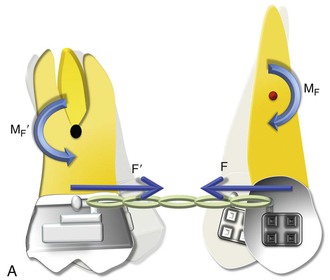
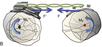
Figure 6-1 Basic dynamics of space closure. A, The magnitude of force for both teeth is equal (F = F′) but the moment due to force (MF) is not necessarily equal (MF ≠ MF′). For the definition of MF, see Chapter 4. B, Occlusal perspective of the same. Tipping will occur in all planes of space.
With efficient mechanical appliances and sound application of the fundamentals learned in Chapter 4, almost any desired tooth movement can be obtained. In a nutshell, the nature of tooth movement can be controlled by applying a counteracting moment (MC) to the MF. In Figure 6-1, the tipping showed can be controlled by this MC. The easiest way to generate this MC is to place a straight wire in the tipped brackets (Fig. 6-2). This ratio of moment to force (MC/F ratio) at the orthodontic bracket can bring about various types of tooth movement. However, the type of tooth movement seen during space closure also depends on the tooth and the objectives of the overall treatment. For example, canines and molars usually need to be translated while the anterior teeth or incisors can do well with simple tipping. Root movement is frequently required for final alignment of the roots, especially during finishing. All these movements require different MC/F ratios as we will see in the next section.
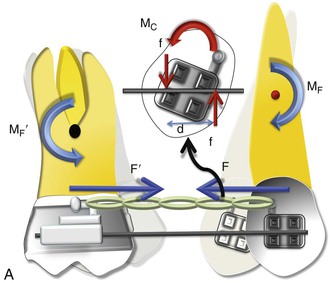
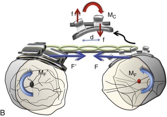
Figure 6-2 Mechanics of uprighting a tipped tooth. A, A simple way to generate a counteracting moment (MC) is to place a straight wire in tipped brackets. The interaction of the MC and moment due to force (MF), or the moment to force (M/F) ratio, dictates the nature of tooth movement. Note that MF = F × distance from the center of resistance (CRES), while MC = F × d (distance between the two couple forces). B, Occlusal perspective of the same. Uprighting will occur due to the wire-bracket interaction. Thus the quality of tooth movement is an interplay of moment due to a couple (in red) and the force (in blue).
Moment to Force (M/F) Ratio
The M/F ratio is a good way to describe or predict the quality of tooth movement. In the literature it has been stated that an M/F ratio of 5 : 1 is required for tipping, of 7 : 1 is required for controlled tipping, of 10 : 1 is required for translation, and of 12 : 1 is required for root correction. However, these ratios cannot be applied universally for all teeth and in all situations. For example, for translation the ratio of 10 : 1 applies for a single rooted tooth where the distance of the bracket or the point of force application is 10-mm from the CRES of the tooth and the amount of force applied is 100 g. A more general way of defining M/F ratio for tooth movement should follow a qualitative approach, not a quantitative approach. High, moderate, and low M/F ratios can do this aptly.
As seen in Chapter 4 and in Figure 6-1, a single force applied at the bracket of a tooth will produce uncontrolled tipping with the center of rotation (CROT) slightly apical to the CRES. Now if a counterbalancing moment (MC) is applied and is high enough, it can perhaps negate the MF. (Note: In Figure 6-2, the MC is generated when the opposite ends and corners of the bracket contact the wire placed in the slot.) This will result in translation. A further increase will cause root movement into the space. At these relatively high M/F ratios, stresses reportedly distribute more evenly through the entire root with minimal changes in the mechanical properties during activation; this reduces injuries to teeth and surrounding tissues. A moderate MC will only partially oppose the MF, leading to controlled tipping with the apex remaining stationary. It is apparent from this discussion that regulating the MC/F (or MC/MF) ratio is key in producing different types of tooth movement for space closure.
However, it is important to mention that the nature of tooth movement can also be regulated by varying the point of force application (see Chapter 4 for a detailed discussion on this).
Anchorage
As discussed, space closure involves the gradual closure of space between two teeth or two segments of teeth when one or both move toward each other. Depending on the needs of the patient, one set of teeth or one tooth can be classified as the active unit while the other is classified as the passive or reactive unit. These two units have completely different roles during tooth movement. The active unit undergoes the majority of the movement while the passive unit resists any kind of movement and provides the resistance necessary to facilitate the movement of the active unit, thereby serving as an anchorage. Therefore anchorage can be defined as the resistance offered by the passive unit toward any type of unwanted movement when the active unit is undergoing the desired movement. The set of teeth that offers this anchorage or resistance is also called the “anchorage unit.” The anchorage setup for different situations can be broadly classified into four types (Fig. 6-3):
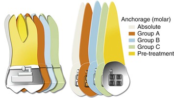
Figure 6-3 Classification of anchorage (for an approximate space of 8 mm). Each increment represents 2 mm. To calculate the movement of a particular shaded tooth, add all increments preceding it. For example, for the green color the molar has move forward by 2 (orange) + 2 (blue) + 2 (green) = 6 mm, while the canine has moved forward only 2 mm. Therefore this represents a group C situation for the canine and a group A situation for the molar.
One of the easiest ways to generate Group A anchorage is by creating a high M/F ratio. In rare situations anchorage might even go beyond absolute anchorage and you might notice a net “anchorage gain.” For example, during en masse retraction of the anterior teeth, the incisors and the molar both can move distally. This sometimes occurs when skeletal anchorage is used to reinforce anchorage.
Methods of Space Closure
Space closure can be accomplished by adopting friction-based mechanics, often called “sliding mechanics,” or without friction, also known as “segmental mechanics” (Fig. 6-4).
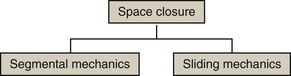
Figure 6-4 Methods for space closure.
Segmental Mechanics
The basic premise of this concept is that all teeth in the upper or lower arch are not connected to each other by a continuous wire but are divided into discrete groups or segments. This segmentation is done on the basis of the role the teeth serve in space closure (i.e., which group of teeth is supposed to move and which is not). The groups are consolidated into segments: active and passive (for anchorage). Force is then applied between these segments to close the extraction space. Since the segments are not connected by a straight wire (i.e., the teeth are not moving on a wire), this is also referred to as “frictionless mechanics.” Closure of space is usually done by loops (potential energy–loaded springs) constructed from regular orthodontic archwires. All closing loops have specific mechanical properties (i.e., response to mechanical forces). Clinicians need to know these properties in order to use them optimally to move teeth or groups of teeth in predetermined directions. In the next section we will elaborate on these properties.
The main mechanical loop properties are the M/F ratio, load and deflection ratios, and the vertical force created. Among these, the M/F ratio can be considered the most significant because it is related to the type of tooth movement.
Concept of Differential Moments
Typically, for severe space closure scenarios a high M/F ratio loop is desirable, while minor spaces can be dealt with loops expressing a low M/F ratio. This is because with more space, teeth have a tendency to show more tipping. Therefore a high M/F ratio will ensure that they remain upright through the space closure.
For example, during incisor retraction the high M/F ratio for the posterior teeth will encourage anchorage preservation as it resists any tipping into the extraction space. In fact, a large posterior moment can cause distal crown movement, thereby opening up more extraction space. On the other hand, the low M/F ratio for the incisors encourages tipping. Simply described, methods using differential M/F ratios may be represented mathematically by the inequality MCp/F ≠ MCa/F and MCp/F ≫ MCa/F (here, a indicates anterior and p indicates posterior).
The application of such unequal moments must also comply with the laws of equilibrium discussed in Chapter 4. Because the moments created at each end of the loop or spring are unequal, the total force system must have additional effects. Vertical forces (intrusive and extrusive) are therefore also acting on the two segments. The magnitude of the vertical force depends on the difference between the two moments and the distance between the two segments.
In contemporary orthodontics, many closing loop shapes are being used, such as vertical or teardrop loops, T-loops, L-loops, Gjessing springs, and others.1–6 These loop types can be further modified by adding a coil, altering the height, tipping the vertical legs (to increase the MC), and so on.
Optimizing Loops for Space Closure: How Loop Design Affects the M/F Ratios
Researchers and clinicians have tried to design and refine loop geometry to obtain the highest M/F ratios possible, with the primary objective of reinforcing anchorage. Mechanical properties of closing loops depend on many factors, such as loop height, width, shape, and position; wire material; cross-sectional dimensions; and so on.4,5,7–9 Let’s look into some of these factors in detail.
Loop Height
Loop height, in particular, affects the M/F ratio considerably. As the loop height increases, the M/F ratio increases. Unfortunately, no loop can reach a M/F ratio greater than its height. Burstone and Koenig7 reported that a 6-mm-high vertical loop had a M/F ratio of approximately 2 whereas a 10-mm-high vertical loop had a M/F ratio of about 4 for a 7-mm horizontal loop length. For a T-loop, as the gingival horizontal length increases, the M/F ratio increases as well to an upper limit and then levels off. Loop length and coil (helix) have only minor effects on the M/F ratio. There is a limit to which the height of a loop can be extended as it starts creating both bending difficulties and inconvenience to the patient when inserted in the mouth.
Loop Shape
The shape of a loop is another important factor to adjust the mechanical properties. The M/F ratio generated by T-loops is higher than that of vertical loops with the same loop height.7,9 A so-called Opus loop introduced by Siatkowski4,5 has an L shape with a helix in the apical portion of the L to increase the M/F ratio. Siatkowski reported that the Opus 70 loop, with the vertical legs tipped 70 degrees backward, had a M/F ratio as high as 8.7 mm, which is much higher than can be obtained by vertical loops or T-loops with similar dimensions. However, L-loops with similar dimensions as the Opus loop have given the highest M/F ratios to date (Fig. 6-5).10
Figure 6-5 An L-loop with a helix.
Loop Placement
The final position of a loop between the active and passive units can significantly modify the M/F ratio.8,11,12 In fact, this is the primary mechanism by which differential moments are created for space closure. This is known as “off-centered positioning of the loop.” Higher moment is produced at the bracket closer to the loop. This principle is directly borrowed from the V-bend principles discussed in Chapter 4. Off-centered V-bends produce a greater moment on the closest tooth. As the loop is activated by horizontal activation (discussed below), the two legs of the loop form an angle with each other (Fig. 6-6). This angle can be further accentuated by placing bends in the loop, thereby increasing the differences in the M/F ratios between the two segments of teeth.
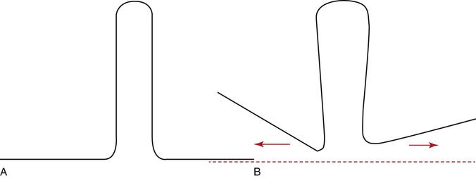
Figure 6-6 A, A typical vertical loop. B, After horizontal activation the two legs are at an angle to each other. This angulation creates a moment opposite in direction to that created by the moment due to a force (MF).
Let us now examine how loop placement and the preactivation bends are clinically used to control space closure. Two clinical situations are presented: canine retraction and incisors retraction.
Segmental Mechanics for Space Closure
Canine Retraction
Canine retraction is the movement of the canine in a distal direction from a position close to the lateral incisors to a position next to the premolar along the gentle curvature of the arch.
Setup.
Let us consider that there is an anteroposterior space of approximately 8-mm to be closed distal to the canine. Before space closure can be initiated with a loop, it is important to ensure that the teeth or segments of teeth to be incorporated for tooth movement or anchorage are adequately aligned so that a 0.021-inch × 0.025-inch stainless steel wire (in a 0.022-inch slot bracket) can be used to hold them as separate units. The only link between the two units should be the loop.
Preactivation of the Loop (Figs. 6-7 and 6-8).
Before the loop can be inserted into the extraction space, certain “preactivation bends” must be placed so that the loop gives a V- or U-shaped outline overall. Remember from Chapter 4 that the mechanics of a loop can be worked out by understanding the geometrie/>
Stay updated, free dental videos. Join our Telegram channel
VIDEdental - Online dental courses


