5
Stud Attachments
Stud attachments have been available on the market for several decades. They are very straightforward to use and provide reasonable retention and stability for implant overdentures.
IMPORTANT CONSIDERATIONS REGARDING THE ALIGNMENT OF STUD ATTACHMENTS
- Relationship of the Stud Attachments with Each Other: Having all of the stud attachments parallel to each other is important. Some universal joint (ball and socket) attachments may be as much as 5–7 degrees out of parallel with each other and still function properly.
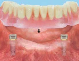
- Relationship of the Stud Attachments with the Path of Insertion: The attachments should not interfere with the path of insertion of the overdenture.
- Height of the Stud Attachments: Achieving an ideal alignment is much more difficult with taller attachments than with shorter ones.
ERA ATTACHMENT
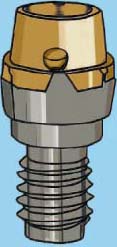
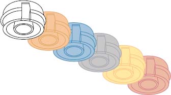
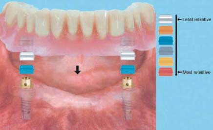
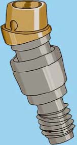
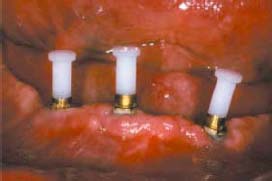
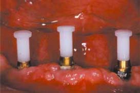
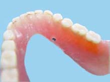
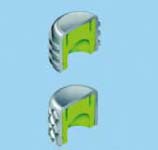
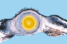
The ERA attachment is a resilient stud attachment that provides hinge and vertical resiliency (Figure 5.1). The fixed component of this attachment is made of titanium alloy with the female attachment portion coated with titanium nitride to decrease attachment wear. The female component comes with different gingival cuff heights: 2mm, 3mm, and 5mm. The nylon male component is captured in the denture acrylic. Six color-coded males correspond to six levels of retention. In order from the least to the most retentive, they are white, orange, blue, gray, yellow, and red (Figures 5.2 and 5.3).
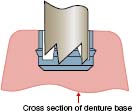
An optional metal housing supports these nylon male components, and the metal housing is preloaded with a black male. The black male is slightly taller (0.4mm) than the final males. Unlike other resilient attachments that have a separate spacer that fits between the male and female during processing, the ERA has a spacer built into the black male. Therefore, when the black male is processed into the denture, removed using two special tools, and replaced with one of the final males, there is 0.4mm of empty space between the male and female. This procedure creates true vertical resiliency and allows a hinging function. Overall height of the male attachment is 3.0mm, and the width of the male is 4.3mm. A new microhead version has a height of only 2.0mm and a width of 3.4mm.
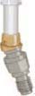
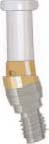
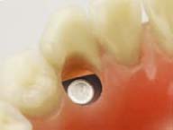
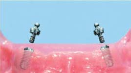
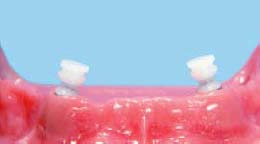
The male attachment (Figures 5.4 and 5.5) accommodates four different implant trajectories: a one-piece with a trajectory of zero degrees, a two-piece with a trajectory of five degrees, a two-piece with a trajectory of 11 degrees, and a two-piece with a trajectory of 17 degrees. The male attachment is available for several implant systems.
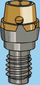
The one-piece, zero degree female component screws directly into the implant. The two-piece angled female component has a polished titanium abutment base and a titanium-nitride-coated female component. The abutment base is screwed into the implant, and the angled female component is cemented into the abutment base using a strong resin or resin ionomer cement.
Chair-Side Utilization Procedure
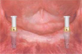
- Using ERA Plastic Handle Gauges: Snap one handle onto a zero-degree, one-piece female and screw the abutment fully into the implant using only finger pressure (Figures 5.6, 5.7, 5.8, 5.9, and 5.10).
- Repeat this step for all of the supporting implants. Next, look at the trajectory of each implant. If at least one implant is positioned in the correct path of insertion for the overdenture, use that implant as a guide to make other abutments parallel to that implant or within a maximum of five degrees out of parallel (Figure 5.11). If none of the implants are positioned in the correct path of insertion, make a pick-up impression and a master cast. Then use a surveyor to determine the discrepancy among the trajectory of the supporting implants.
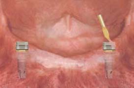
- Using an ERA Angle Correction Gauge Kit: There are four different alignment metal gauges (0, 5, 11, and 17 degrees) that can be use to determine the discrepancy between the trajectory of the supporting implants. The gauges are made of polished titanium. These gauges can be inserted into the screw access holes of most implant systems. These gauges have no thread pattern, just a smooth pin that slides into the screw access hole of the implant. After insertion of the gauge into the implant, manually rotate the gauge until it reaches an ideal trajectory that is aligned with the path of insertion of the overdenture. Choose the proper angled female abutment for each implant by checking the laser mark on each gauge.

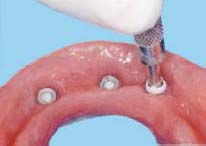
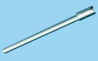
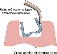
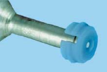
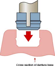
Changing ERA Male Component
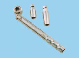
Note: A dentist’s tool kit (core cutter and seating tool) is necessary for replacement of ERA males.
VKS-OC RS STUD ATTACHMENT
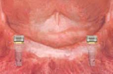
The Vario Ball-Snap-OC rs stud attachment abutment is designed for implant overdentures that are partly implant born and partly tissue born (Figures 5.29, 5.30, 5.31, 5.32, 5.33, 5.34, and 5.35).

This stud attachment is available for the following implants:
- Branemark 3.75 mm, 4.0 mm, 5.0 mm
- 3i external hex 4.0 mm, 5.0 mm, 6.0 mm
The VKS-OC rs stud attachment is available in the following three cuff heights:
- 2mm
- 4mm
- 6mm
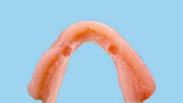
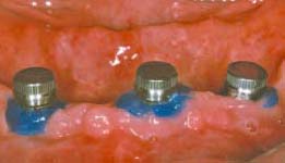
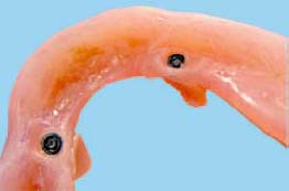
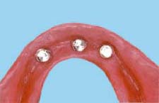
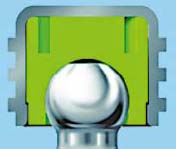
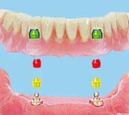
The male part (ball) of this attachment assembly will be screwed into the implant, and the female matrices will be secured inside the acrylic denture base.
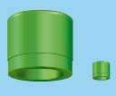
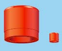
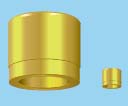
Different Types of Matrices/Clips
Rigid:
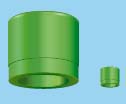
- Green: Low retention (Figure 5.36)
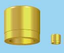
- Yellow: Medium retention (Figure 5.37)
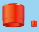
- Red: Strong retention (Figure 5.38)
This attachment system can be utilized in either of the following two ways:
- Embedded in the acrylic denture base (Figure 5.39)
- Cast within the chrome cobalt framework (Figure 5.40)

Clinical and Laboratory Procedures for VKS-OC rs Attachment Embedded in the Acrylic Denture Base
CLINICAL STEPS
- Brand of the implant
- Diameter of the implant
- Thickness of the gingiva
LABORATORY STEPS

Stay updated, free dental videos. Join our Telegram channel
VIDEdental - Online dental courses


