Chapter 3 Diagnostic Imaging and Techniques
Diagnostic imaging and techniques help develop and implement a cohesive and comprehensive treatment plan for the implant team and the patient. The implant team requires the services or functions of a number of professionals and may include the referring dentist, laboratory technician, prosthodontist, periodontist, oral surgeon, implantologist, anesthesiologist, radiologist, hygienist, and staff. Information acquired from the patient’s medical and dental history, including clinical examination, laboratory tests, diagnostic casts, diagnostic wax-up, and diagnostic imaging, plays a role in developing the patient’s treatment plan and objectives.
IMAGING MODALITIES
Maximizing the ratio of benefit to risk for imaging examinations is a fundamental tenet of radiology. Examinations known to produce this result are not necessarily the examinations that cost the least, are in proximity to the dentist, or produce the lowest radiation exposure.1–3 However, they enable the dentist to provide the proper care or treatment for the patient.
Many imaging modalities have been reported as useful for dental implant imaging, including devices recently developed specifically for dental implant imaging (Box 3-1).4,5
These imaging modalities can be described as analog or digital and two- or three-dimensional. Most dentists are more familiar with analog two-dimensional imaging (see Box 3-1). Analog imaging modalities are two- dimensional systems that use radiograph film or intensifying screens as the image receptors. The image quality of these systems is characterized by resolution/modulation transfer function, contrast/H and D curve, noise/Weiner spectrum, and sensitivity.6 The clinical performance of these imaging systems is gauged by receiver operator characteristics.7,8
Digital images also can be produced with each imaging modality (see Box 3-1). A digital two-dimensional image is described by an image matrix that has individual picture elements called pixels. A digital image is described by its width and height and pixels (i.e., 512 × 512). For larger digital images (i.e., 1.2 × 1.2 M, where M is megapixels), the image is alternatively described as a 1.5-M image. Each picture element, or pixel, has a discrete digital value that describes the image intensity at that particular point. The value of a pixel element is described by a scale, which may be as low as 8 bits (256 values) or as high as 12 bits (4096 values) for black-and-white imaging systems, or 36 bits (65 billion values) for color imaging systems.9–11 Black-and-white digital images are displayed optimally on a dedicated black-and-white monitor. Generally, 8 bits or 256 levels can be displayed effectively on a monitor.
A digital three-dimensional image is described by an image matrix that has individual image/picture elements called voxels. A digital three-dimensional image is described not only by its width and height and pixels (i.e., 512 × 512) but also by its depth/thickness. An imaging volume or three-dimensional characterization of the patient is produced by contiguous images, which produce a three-dimensional structure of volume elements (i.e., computed tomography [CT], magnetic resonance imaging [MRI], and interactive computed tomography [ICT]). Each volume element has a value that describes its intensity level. Typically, three-dimensional modalities have an intensity scale of 12 bits or 4096 values. Box 3-1 identifies the three-dimensional imaging modalities.
PRESURGICAL IMAGING (PHASE 1)
The goal of presurgical radiographic evaluation is to assess the available bone quality and quantity, angulation of bone, selection of potential implant sites, and to verify absence of pathology. However, there exists no ideal radiographic imaging technique in the field of oral implantology that would be acceptable for all patients. All imaging techniques in the field of dentistry have inherent advantages and disadvantages and have been shown to exhibit false-negative and false-positive images.12–14
When selecting a radiographic modality for preoperative assessment, a careful examination of the available imaging options should be evaluated for selection as per the patient’s needs. In dental and medical radiology, a recommended principle when selecting the appropriate radiographic modality is based on radiation dosage. The “as low as reasonably achievable” (ALARA) principle should always be adhered to that states that the diagnostic imaging technique selected should include the lowest possible radiation dose to the patient. However, patient care and treatment planning should not be jeopardized in response to radiation dose. Studies have shown that an overwhelming number (90%) of dentists prescribe panoramic images as the sole determinant for implant treatment planning.15,16 In comparison, less than 10% prescribe conventional or CT. On the other hand, the American Academy of Oral and Maxillofacial Radiology guidelines state that all implant site evaluations should be evaluated with a three-dimensional imaging technique such as conventional or computerized tomography.17
The global objective of this phase of treatment is to develop and implement a treatment plan for the patient that enables restoration of the patient’s function and esthetics by the accurate and strategic placement of dental implants. The patient’s functional and esthetic needs can be transformed physically into a three-dimensional diagnostic template, which enables the implant team to identify the specific sites of prospective implant surgery in the imaging examinations. The specific objectives of preprosthetic imaging listed in Box 3-2.
All the modalities identified in Box 3-1 have been used in the first diagnostic phase of treatment.4,5 However, dental implant cases are inherently three-dimensional problems relating to the final prosthetics, occlusion, and function of the patient’s three-dimensional anatomy. A three-dimensional treatment plan ideally identifies at each prospective implant site the amount of bone width, the ideal position and orientation of each implant, its optimal length and diameter, the presence and amount of cortical bone on the crest, the degree of mineralization of trabecular bone, and the position or relationship of critical structures to the proposed implant sites. Thus the modalities of choice for presurgical implant treatment planning provide high-resolution and dimensionally accurate three-dimensional information about the patient at the proposed implant sites.
The imaging modalities listed in Box 3-1 can be subdivided into planar two-dimensional, quasi—three-dimensional, and three-dimensional imaging modalities. Planar imaging modalities include periapical, bite-wing, occlusal, and cephalometric imaging and are simply two-dimensional projections of the patient’s anatomy. Thus the dentist cannot possibly develop a three-dimensional perspective of the patient’s anatomy with a single image. However, with a number of cleverly oriented projections, development of some useful three-dimensional information is possible.
PERIAPICAL RADIOGRAPHY
Periapical radiographs are images of a limited region of the mandibular or maxillary alveolus. Periapical radiographs are produced by placing the film intraorally parallel to the body of the alveolus with the central ray of the x-ray device perpendicular to the alveolus at the region of interest, producing a lateral view of the alveolus.18 Periapical radiography provides a high-resolution planar image of a limited region of the jaws.19 Number 2 size dental film provides a 25 × 40-mm view of the jaw with each image. Periapical radiographs provide a lateral view of the jaws and no cross-sectional information. Even with adjacent periapical radiographs made with limited oblique orientations, three-dimensional information is of little use for the implant imaging (Box 3-3).
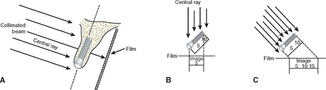
Image shape distortion occurs when unequal magnification of the object exists. This will occur when the total area in question (alveolar bone, implant) does not have the same focal spot-to-object distance. When the x-ray beam is perpendicular to the object, but the object is not parallel to the film, foreshortening will occur. If the x-ray beam is oriented perpendicular to the object but not the film, elongation will occur (Figure 3-1). These basic and important concepts will help minimize distortion and magnification when using intraoral radiographs.20
The bone density at the crest is also a factor to evaluate crestal bone loss with radiographic indexes. In D4 bone, no cortical plate is present on the crest, and fine trabecular bone is primarily present. Burnout effects are common when standard kilovolt and milliampere settings are used, making crestal bone loss evaluation with digital intraoral systems of benefit in these situations.21–23
In terms of the objectives of presurgical imaging, periapical radiography is:
DIGITAL RADIOGRAPHY
One of the most recent significant advances in dental radiology is the advent of digital technology that has allowed numerous limitations of conventional intraoral radiography to be reduced. The advantages of digital radiography and the uses in oral implantology are well documented.24,25 With the use of digital radiography, implant surgical procedures and prosthetics have been simplified with increased efficiency.
Digital radiology is an imaging process wherein the film is replaced by a sensor that collects the data. The analog information received is then interpreted by specialized software, and an image is formulated on a computer monitor. The resultant image can be modified in various ways, such as gray scale, brightness, contrast, and inversion. Color images may be formed to enhance the digital image for better evaluation. Computerized software programs (i.e., DexisImplant) are now available that allow for calibration of magnified images, thus ensuring accurate measurements (Figure 3-2).
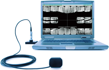
Figure 3-2 Digital radiographic system that includes digital sensor and computer.
(Courtesy Dexis, LLC.)
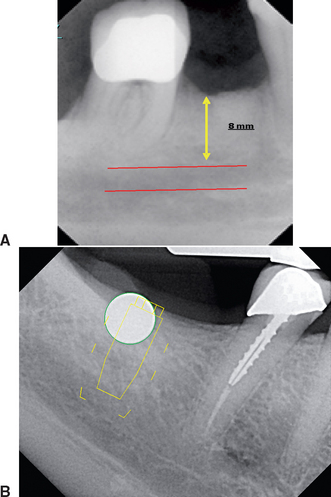
When compared with conventional radiographs, the most current digital systems have significantly less radiation26,27 with superior resolution.25 However, with respect to oral implantology, the most significant advantage of digital radiography is the instantaneous speed in which images are formed that is highly useful during surgical placement of implants and the prosthetic verification of component placement (Figure 3-3).
A disadvantage of digital radiography is the size and thickness of the sensor and the position of the connecting cord. These features make the positioning of the sensor more difficult in some sites such as those adjacent to tori or a tapered arch form in the region of the canines (Table 3-1).28
| FILM | DIGITAL | |
|---|---|---|
| Image | Analog | Analog → Digital |
| Cost | Film, chemicals | Up-front |
| Radiation | High | 50%-90% less |
| Viewing | Delayed | Immediate |
| Resolution | 14-18 Ln/mm | 12-20 Ln/mm |
| Grayscale | 16 shades | 256 shades |
| Film | Thin, flexible | Thin, cord |
| Enhancement | Unchangeable | Wide range |
| Storage | Chart | Computer |
From Park ET, Williamson GF: Digital radiography: an overview, J Contemp Dent Pract 3:1-13, 2002.
OCCLUSAL RADIOGRAPHY
Occlusal radiographs are planar radiographs produced by placing the film intraorally parallel to the occlusal plane with the central x-ray beam perpendicular to the film for the mandibular image and oblique (usually 45 degrees) to the film for the maxillary image. Occlusal radiography produces high-resolution planar images of the body of the mandible or the maxilla.19 Maxillary occlusal radiographs are inherently oblique and so distorted that they are of no quantitative use for implant dentistry for determining the geometry or the degree of mineralization of the implant site. In addition, critical structures such as the maxillary sinus, nasal cavity, and nasal palatine canal are demonstrated, but the spatial relationship to the implant site generally is lost with this projection (Box 3-4).
Because the mandibular occlusal radiograph is an orthogonal projection, it is a less-distorted projection than the maxillary occlusal radiograph. However, the mandibular alveolus generally flares anteriorly and demonstrates a lingual inclination posteriorly, producing an oblique and distorted image of the mandibular alveolus, which is of little use in implant dentistry. In addition, the mandibular occlusal radiograph shows the widest width of bone (i.e., the symphysis) versus the width at the crest, which is where diagnostic information is needed most (Figure 3-4). The degree of mineralization of trabecular bone is not determined from this projection, and the spatial relationship between critical structures, such as the mandibular canal and the mental foramen, and the proposed implant site is lost with this projection. As a result, occlusal radiographs rarely are indicated for diagnostic presurgical phases in implant dentistry.
CEPHALOMETRIC RADIOGRAPHY
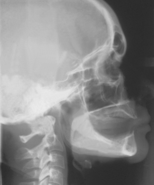
Cephalometric radiographs are oriented planar radiographs of the skull. The skull is oriented to the x-ray device and the image receptor using a cephalometer, which physically fixes the position of the skull with projections into the external auditory canal. The geometry of cephalometric imaging devices results in a 10% magnification of the image with a 60-inch focal object and a 6-inch object-to-film distance.19
A lateral cephalometric radiograph is produced with the patient’s midsagittal plane oriented parallel to the image receptor. This radiograph demonstrates a cross-sectional image of the alveolus of the mandible and the maxilla in the midsagittal plane.21 With a slight rotation of the cephalometer, a cross-sectional image of the mandible or maxilla can be demonstrated in the lateral incisor or in the canine regions. Unlike panoramic or periapical images, the cross-sectional view of the alveolus demonstrates the spatial relationship between occlusion and esthetics with the length, width, angulation, and geometry of the alveolus and is more accurate for bone quantity determinations. Implants often must be positioned in the anterior regions adjacent to the lingual plate.
The lateral cephalometric radiograph is useful because it demonstrates the geometry of the alveolus in the mid-anterior region and the relationship of the lingual plate to the patient’s skeletal anatomy (Figures 3-5 and 3-6; Box 3-5). The width of bone in the symphysis region and the relationship between the buccal cortex and the roots of the anterior teeth also may be determined before harvesting this bone for ridge augmentation. Together with regional periapical radiographs, quantitative spatial information is available to demonstrate the geometry of the implant site and the spatial relationship between the implant site and critical structures such as the floor of the nasal cavity, the anterior recess of the maxillary sinus, and the nasal palatine canal. The lateral cephalometric view also can help evaluate a loss of vertical dimension, skeletal arch interrelationship, anterior crown/implant ratio, soft tissue profile, anterior tooth position in the prosthesis, and resultant moment of forces. As a result, cephalometric radiographs are a useful tool for the development of an implant treatment plan, especially for the completely edentulous patient. However, this technique is not useful for demonstrating bone quality and only demonstrates a cross-sectional image of the alveolus where the central rays of the x-ray device are tangent to the alveolus.
PANORAMIC RADIOGRAPHY
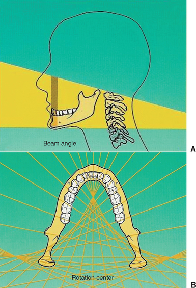
Panoramic radiography is a curved plane tomographic radiographic technique used to depict the body of the mandible, the maxilla, and the lower half of the maxillary sinuses in a single image. This modality is probably the most used diagnostic modality in implant dentistry. However, for quantitative presurgical implant imaging, panoramic radiography is not the most diagnostic. This radiographic technique produces an image of a section of the jaws of variable thickness and magnification. The image receptor traditionally has been radiograph film but may be a digital storage phosphor plate or a digital charge—coupled device receptor.23,29,30 Nonetheless, panoramic images offer many advantages (Box 3-6).
The significant limitations of panoramic radiographs can be classified into two categories: (1) distortions inherent in the panoramic system and (2) errors in patient positioning. Panoramic radiography is characterized by a single image of the jaws that demonstrates vertical and horizontal magnification, along with a tomographic section thickness that varies according to the anatomical position. The x-ray source exposes the jaws from a negative angulation and produces a relatively constant vertical magnification of approximately 10%. The horizontal magnification is approximately 20% and variable depending on the anatomical location, the position of the patient and the focus object distance, and the relative location of the rotation center of the x-ray system. Clinical data have shown that nonuniform magnification may be in the range of 15% to 220%.31–33 Structures of the jaws become magnified more as the object-film distance increases and the object—x-ray source distance decreases.
Structures that are located obliquely in relation to the implant receptor produce aspects of the structures that are magnified more when they are farther from the image receptor and less when they are closer to the image receptor.34–36 Uniform magnification of structures produces images with distortion that cannot be compensated for in treatment planning. The posterior maxillary regions are generally the least distorted regions of a panoramic radiograph. The tomographic section thickness of panoramic radiography or trough of focus is thick, approximately 20 mm, in the posterior regions and thin, 6 mm, in the anterior region.36
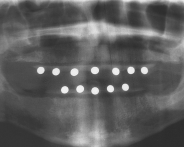
Because the concept of standardized magnification is impossible and unreliable, most clinical studies have observed the inaccuracies of direct measurements of panoramic radiographs37,38 (Figure 3-7).
Inherent magnification is dependent upon patient positioning errors, which results in significant geometric distortion. With knowledge, most errors in patient positioning can be corrected (Table 3-2). However, in a given plane, horizontal distortion cannot be determined and measurements are completely unreliable. The horizontal dimensions are affected by the rotation center of the beam that changes with relation to the object-film distance.26
Table 3-2 Common Panoramic Positioning Problems and Corrections
| PROBLEM | CAUSE | CORRECTION |
|---|---|---|
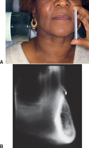
The vertical dimensions are dependent upon the x-ray source as the focus with the amount of distortion determined by the distance of the patient’s arch to the film. However, vertical magnification may be determined by imaging a known-diameter object close to the alveolar ridge. The magnification factor can be calculated at the given site by dividing the actual diameter of the object by the diameter measured on the radiographic image. Diagnostic templates that have 5-mm ball bearings or wires incorporated around the curvature of the dental arch and worn by the patient during the panoramic x-ray examination enable the dentist to determine the amounts of magnification in the radiograph (Figure 3-8). A technique for evaluating the panoramic radiograph for mandibular posterior implants and comparison with the clinical evaluation during surgery was developed by identifying the mental foramen and the posterior extent of the inferior alveolar canal.39 However, studies have demonstrated that the mandibular foramen cannot be identified 30% of the time on the radiograph film and, when visible, may not be identified correctly.40–43 The maxillary anterior edentulous region is generally oblique to the film and is often the most difficult area of a panoramic radiograph to evaluate because of the curvature of the alveolus and the inclination of the bone. The dimensions of inclined structures in panoramic radiographs are not reliable. Studies on panoramic x-ray units have demonstrated that objects in front of and behind the focal trough are blurred, magnified, reduced in size, or distorted to the extent of being unrecognizable.
TOMOGRAPHY
Many ingenious tomographic methods and devices have been developed. However, the basic principle of tomography is that the x-ray tube and film are connected by a rigid bar called the fulcrum bar, which pivots on a point called the fulcrum. When the system is energized, the x-ray tube moves in one direction with the film plane moving in the opposite direction and the system pivoting about the fulcrum. The fulcrum remains stationary and defines the section of interest, or the tomographic layer. Different tomographic sections are produced by adjusting the position of the fulcrum or the position of the patient relative to the fulcrum in fixed geometry systems.6
Stay updated, free dental videos. Join our Telegram channel
VIDEdental - Online dental courses


