Chapter 11 Scientific Rationale for Dental Implant Design
The treatment planning sequence for implant dentistry begins with the design of the final restoration.1 After the position and number of teeth replaced and type of prosthesis are determined,2 the patient force factors are evaluated.3 The greater the force factors, the greater the implant support required. The bone density in the region of the implant abutments is then considered, with poorer bone densities requiring a greater amount of implant support.4 The key implant positions and additional implant number are then determined, followed by the ideal implant size.5 The available bone in the edentulous sites is then evaluated.6 When the bone available is present for the size, number, and position of the implants for the planned prosthesis, the treatment proceeds with little compromise. When the bone is not present, a modification of the treatment is necessary. These modifications include: (1) bone augmentation to fulfill the ideal treatment plan; (2) consideration of optional implant locations, usually with additional implants, or an increase in implant size; or (3) optimization of implant design. A favorable implant design may compensate for risk for occlusal loads in excess of normal, poor bone densities, less than ideal implant position or number, or less than an ideal implant size.7
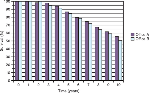
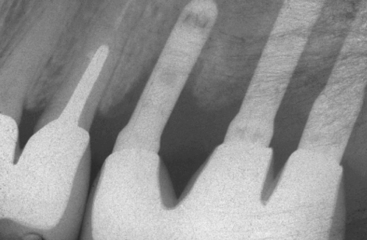
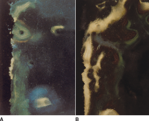
A cylinder or press-fit implant has a friction-fit insertion and may have less risk of pressure necrosis from too tight an insertion pressure, has no need to bone tap (even in dense bone), and may have the cover screw already in place because no rotational force is required to insert the implant. As a result, cylinder or press-fit implants are the easiest to insert, were very popular in the 1980s, and were reported to have high initial success rates.8,9 However, after 5 years of loading, reports of the cylinder implant include loss of crestal bone and implant failure more often observed (Figure 11-1).10 Most likely, this was related to a fatigue overload condition and harmful shear loads on the bone causing large bone turnover rates, and ultimately less bone-implant contact percent and higher risk of overload failure.
The most predictable aspect of implant dentistry appears to be the surgical success. After many years of clinical studies and evaluations, the surgical success rate from implant insertion to uncovery of the implant is usually higher than 98%, regardless of the implant design or size.11–14 As such, designing an implant for surgical ease does not appear to be the most important aspect of the overall implant-prosthetic—related process to reduce the incidence of complications.
Another focus of several implant designs is to reduce the plaque-related complications of treatment. With this concept in mind, one consistent implant body design features smooth metal surfaces at the crestal portion of the implant. A smooth crest module (the area between the implant body and prosthetic platform) of the implant is easier to clean related to oral hygiene methods and collects less plaque than rougher surfaces.15 Therefore the rationale is that if bone loss occurs at the marginal regions of the implant, the smooth implant surface will harbor less plaque and be easier to clean.
The problem with this philosophy is the smooth crest module is initially placed below the crest of the bone and is a design that encourages marginal bone loss from the extension of a biological width after implant uncovery and from shear forces after occlusal loading.16,17 As a result, this plaque-reducing design feature increases the peri-implant sulcus depth. Paradoxically, the feature designed to decrease bacteria complications actually increases the risks. Therefore an implant body designed for ease of surgery or to reduce peri-implantitis complications most often does not address the most common complications observed in implant prostheses.
Most implant body complications in the literature are related to early implant failure after loading, marginal bone loss before loading but after exposure of the implant, and marginal bone loss after the loading of the implant-bone interface.18 Implant failures are most often observed as early loading failures in softer bone types or shorter implant lengths. A review of the literature by Goodacre et al. between 1981 and 2003 found that, after the implant was loaded, failure rates increased to an average of 16% in soft bone.18 Misch reviewed the literature between 1981 and 2004 and found an overall 18% failure rate in implants shorter than 10 mm.19 For example, Weng et al. reported in a multicenter study of 6 years, implant initial healing survival higher than 98%, but 7-mm implants failed 25% of the time within 18 months of loading and short implants in the posterior maxilla had the highest early loading failure of any intraoral region.20 Therefore implant body designs should attempt to primarily address the primary causes of complications (i.e., the factors that address the loading conditions of the implant after the implants are placed in function).
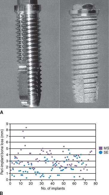
Different implant survival rates and different marginal bone loss after loading have been reported for different implant body designs. A report by Zechner et al. evaluated the peri-implant bone over a 3- to 7-year period around functionally loaded, screw-type implants with a machined surfaced V-thread and sandblasted, acid-etched, square-thread design.21 Both these implants had a similar crest module and external hex connection. The range of bone loss in the study was 0.1 to 8.5 mm for the machined V-thread and 0.2 to 4.8 mm for the rough surface, square-threaded implant. There were 22 V-threaded implants that lost more than 4 mm of bone compared with three square-threaded implants. Bone loss of less than 1 mm was reported for 16 rough surface implants compared with only two machined surface implants (Figure 11-2). The range of bone loss and the incidence of bone loss both indicate implant design or surface condition made a difference in this report.
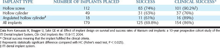
A prospective report by Karoussis et al. also indicated that different implant designs yield different incidences of crestal bone loss.22 Three different implant designs from the same manufacturer (Straumann ITI Dental Implant Systems, Basel, Switzerland) were evaluated with a prospective study over 10 years (Table 11-1). The survival rate of each design over this time was 95.4% versus 85.7% versus 91.2%. The implant with the highest survival rate (hollow screw design) lost more than 5 mm of bone in 26% of the implants, whereas the two other designs reported 37% and 39% incidence of greater than 5-mm bone loss. More than 6 mm of marginal bone loss occurred in 22% of implants with the first design and in 35% and 33% for the other two designs. Therefore implant survival and marginal bone loss was related to implant design.
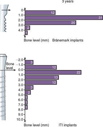
In a 3-year clinical study, a different amount of marginal bone loss was reported between the Nobel Biocare Brånemark implant and the Straumann ITI implant, with ITI having a greater range of bone loss after loading (Figure 11-3).23 The microgap and machined surface of the Nobel implant caused less bone loss than the rough cylinder shape at the crest after loading with ITI. In other words, several clinical reports found different implant designs influence not only the implant survival, but also the amount of early crestal bone loss after loading. This chapter will build on and apply basic biomechanics and demonstrate how these principles are related to implant design in order to decrease the more common complications observed in implant dentistry.
IMPLANT DESIGN RELATED TO OCCLUSAL FORCES
Force Type and Influence on Implant Body Design
Three types of forces may be imposed on dental implants within the oral environment: compression, tension, and shear. Bone is strongest when loaded in compression, 30% weaker when subjected to tensile forces, and 65% weaker when loaded in shear.24 An attempt should be made to limit shear forces on bone, because it is least resistant to fracture under these loading conditions. This is most important in regions of decreased bone density, because the strength of bone is also directly related to its density.25
Smooth-sided, cylindrical implants provide ease in surgical placement; however, the bone-implant interface is subject to significantly larger shear conditions. In contrast, a smooth-sided, cylindrical, tapered implant provides for a component of compressive load to be delivered to the bone-implant interface, depending on the degree of taper.26 The greater the taper, the greater the component of compressive load delivered to the interface. Unfortunately, the amount of taper cannot be greater than 30 degrees or the implant body length is significantly reduced, along with the immediate fixation required for the initial healing. As a negative feature, the greater the taper of a smooth-sided implant, the less the overall surface area of the implant body under load and the less initial stability provided by that implant at an immediate extraction and implant insertion.
Unlike a cylinder implant, a tapered threaded implant serves no functional surface area advantage, because the threads of a screw bear the compressive loads to the bone. The tapered, threaded implant provides some surgical advantage during initial insertion, because it inserts down within the osteotomy halfway before engaging bone. However, the lesser surface area of a tapered implant increases the amount of stress at the crestal portion, as demonstrated in three-dimensional finite element studies.27 In addition, in a tapered threaded implant, threads at the apical half are often less deep, because the outer diameter continues to decrease. This limits the initial fixation of the implant.
A smooth-cylinder implant body results in essentially a shear load at the implant-bone interface. Bone grows to a cylinder-shape implant during initial healing. However, this type of body geometry must rely on a microscopic retention system such as roughening or coating (acid etch, mechanical etch, or coatings such as titanium plasma spray or hydroxylapatite [HA]) for the initial loading period.28 The integrity of the implant interface during initial loading is therefore dependent on the shear strength of the implant surface-to-bone bond. The quality of the coating (e.g., HA) is absolutely paramount in such applications.29 If the HA is altered from friction during implant surgical insertion, infection, mechanically removed during treatment of peri-implantitis or from bone remodeling over years of function, the remaining smooth-sided cylinder is severely compromised for healthy load transfer to the surrounding tissues (Figure 11-4).30
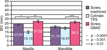
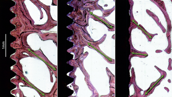
The surface conditions of an implant may enhance bone-implant contact (BIC) and adhesion qualities to the bone-implant interface at initial healing. However, the surface coatings on cylinders do not permit compressive forces to be effectively transmitted to the bone cells, because the microfeatures of the coating are too small for the cells to be loaded in compression.31 Therefore the surface area—bone contact percentage is greater during initial healing, but the functional surface area over which loads are effectively dissipated during long-term loading to the surrounding bone is most dependent on the macroscopic design of the implant body. For example, Watzek et al. evaluated screw shape and cylinder implants with histologic and histomorphometric analysis after 18 months of occlusal loading in baboons.32 There was a significant difference in BIC, with screw-type implants having higher values in both the maxilla and mandible (Figure 11-5).32 In addition, the trabecular bone pattern was irregular around the cylinder implants, but the bone was organized perpendicular to the threads around the screw implants (Figure 11-6).32 Therefore the bone trabeculae pattern and the higher BIC resulted in a superior support system for threaded implants.
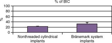
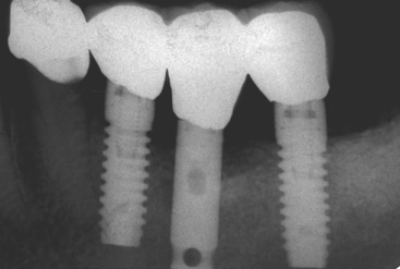
An implant retrieval clinical report by Bolind et al. evaluated cylinder implants compared with threaded implants from functioning prostheses.33 Consecutively retrieved oral implants from 117 patients, with 85 cylinder implants and 85 threaded implant designs, were evaluated. Greater BIC was found around threaded implants, and greater marginal bone loss was observed around cylinder implants (Figure 11-7).33 It should be noted the cylinder implants in this report had a roughened surface condition, whereas the threaded implants had a machined surface. Numerous reports demonstrate roughened surfaces have higher BIC compared with machined surfaces. In this human retrieval report, therefore, implant body design was more important than the surface condition of the implant for crestal bone loss and overall BIC after loading. In Figure 11-8, an HA-coated cylinder is splinted to two HA-coated threaded implants. More crestal bone loss is observed on the cylinder implants.
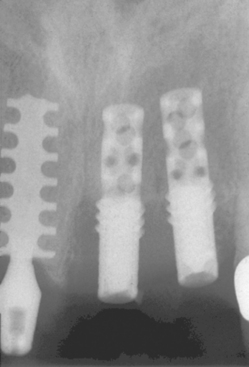
Any smooth shear surface on an implant body increases the risk of bone loss because of inadequate load transfer.34 Figure 11-9 depicts one such example characterized by extensive crestal resorption adjacent to a long, smooth shear surface on the two implant bodies (Core-Vent/Paragon implant). The crestal bone loss contributed to an increase in crown height (which further magnifies stress from bending moments) and the fracture of two abutments. The implant body next to these cylinder-type implants was loaded in the same prosthesis, yet the plateau implant body design (which is a compressive load design) maintained bone height over the years of loading.
Force Direction and Influence on Implant Body Design
Bone is weaker when loaded under an angled force.35 The greater the angle of load, the greater the stresses to the implant-bone interface. The noxious effect of angled loads to bone is further exacerbated because of the anisotropy of bone.36 Anisotropy refers to how the character of bone’s mechanical properties, including ultimate strength, depends on the direction in which the bone is loaded. A 30-degree angled load will increase the overall stress by 50% compared with a long axis load, especially around the crestal portion of the implant.37 Therefore, under ideal conditions, the implant body long axis should be perpendicular to the curve of Wilson and curve of Spee to apply a long axis load to the implant during occlusal load in centric occlusion (where the occlusal forces are usually the greatest). As the angle of load to the implant-bone interface increases, the stresses around the implant increase. As a result, virtually all implants are designed for placement perpendicular to the occlusal plane. Additionally, axial alignment places less shear stress on the overall implant system (i.e., porcelain, cement, abutment and abutment screw components, crestal bone, implant body, and implant-bone interface) and decreases the risk of complications, as screw loosening and fatigue fractures.
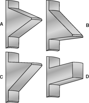
Implant body designs with threaded features have the ability to convert occlusal loads into more favorable compressive loads at the bone interface; therefore thread shape is particularly important when considering long-term load transfer to the surrounding bone interface (Figure 11-10). Under axial loads to an implant-bone interface, a buttress or square-shaped thread (typical of BioHorizons, BioLok, and Ankylosis) would transmit compressive forces to the bone. Under axial loads to a dental implant, a V-thread face angle (typical of implants from Zimmer, LifeCore, 3i, and some Nobel Biocare designs) is comparable to the reverse buttress thread (typical of some Noble BioCare designs) because of the similarity in the inferior portion of the thread face angle.
A reduction in shear load and subsequent shear stresses at the thread-bone interface reduces the risk of bone failure and possible reduced bone-implant contact percent of the implant if all the other factors are equal, which is particularly important in compromised bone densities or shorter implant lengths.38 The thread shape (macroscopic design) is independent from the surface coating (microscopic design). For example, any threaded implant surface may also be textured with HA coating or other roughened surface conditions to enhance osteointegration and increase the bone-implant contact percent during initial healing.
IMPLANT BODY: FUNCTIONAL VERSUS THEORETICAL SURFACE AREA
For a given bone volume, implant surface area should be optimized for functional loads. Thus an important distinction is made between theoretical total surface area and functional surface area of an implant. Because bone is 65% weaker to shear forces and 35% weaker to tensile forces, functional surface area is defined as the area that actively serves to dissipate compressive loads to the implant-bone interface.38 Functional thread surface area, therefore, is that portion of the thread that participates in compressive load transmission under the action of an axial (or near-axial) occlusal load.
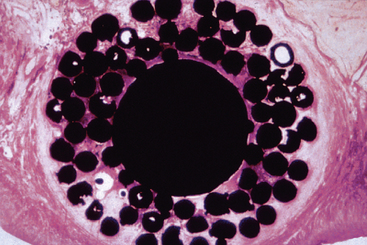
In contrast to functional surface area is total theoretical surface area, which may include a “passive” area on the implant that does not participate in load transfer, or has a feature so small bone cannot adapt to load transfer. For example, plasma spray coatings are often reported to provide up to 600% more total surface area for the potential bone-implant contact.26 However, the size of each plasma spray particle is less than 8 μm, and the 120-μm bone cell does not receive a transfer of mechanical stress from this feature. The amount of actual BIC that can be used for compressive loading may be less than 30% of the total theoretical surface area (Figure 11-11).
An improved functional surface area per unit length of the implant (in contrast to total surface area) is beneficial to reduce the mechanical stress to bone. Most stress to the implant-bone interface in D1 to D3 bone is in the crestal 5 to 9 mm of the implant; therefore the design of the implant body in the coronal 9 mm is most important to appropriately distribute occlusal stresses to the bone.27,39,40 For example, a conventional 20-mm V-shaped or reverse buttress-threaded implant of a constant thread depth may have more total surface area compared with a 13-mm square threaded or plateau design implant. The functional area, however, that is available to resist compressive biomechanical loads in the zones of greatest stress to the BIC may be significantly higher in the 13-mm implant because of the thread geometry.
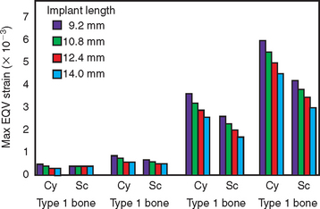
Functional surface area also plays a major role in addressing the variable initial BIC zones related to bone density upon initial loading. D1 bone, the densest bone found in the jaws, is also the strongest, has the stiffest modulus of elasticity, and has the highest initial BIC percent, which approximates 80%. D2, D3, and D4 bone have progressively decreasing percentages of bone at the initial implant interface, with D4 bone ranging around 25% interface contact at the initial healing and uncovery of a machined titanium implant.4,41 As a result, the implant geometric body design, length, and bone density are related to the functional surface area. For example, in more compromised bone sites (i.e., D4 bone), longer implants are required to resist off-axis and moment loads because of cantilevers, improper occlusion, or parafunction.42 Recall that mechanical stress is equivalent to the applied load divided by the surface area over which the load is dissipated. D4 bone has the weakest biomechanical strength and the lowest BIC area to dissipate the load at the implant-bone interface. The functional surface area requirements would increase from a minimum for an implant in D1 bone to a maximum for implants in the D4 bone (Figure 11-12).42
The diameter of an implant may influence the length requirements of the implant body, because the functional surface area is increased. However, the higher bite forces and lower bone density of the posterior regions of the mouth may not always be able to be addressed adequately by only implant diameter. For example, Ivanoff et al. in 1999 found 6-mm-long implants with a 5-mm diameter had a failure rate of 33% in the mandible and 10% in the maxilla.44 The 8-mm-long, 5-mm-diameter implant yielded 33% and 25% failure rates in the mandible and the maxilla, respectively. On the other hand, the longer 10-mm and 12-mm implants that were 5 mm in diameter yielded no mandibular failures and a 10% failure rate in the maxilla. Therefore the 5-mm implant diameter was not enough to compensate for the shorter implants in this report.
An ideal treatment plan would include implant length of 12 mm or greater with 4-mm diameter for most anterior implant sites and 5 mm or greater in the molar regions.5 When the ideal implant size cannot be inserted because of inadequate bone, an alternative to bone augmentation may be to increase the surface area of the implant by modifying the implant body design.
IMPLANT BODY GEOMETRY VERSUS OCCLUSAL LOAD
Different implant survival rates and amounts of marginal bone loss may be directly related to different implant body designs. The macrodesign of an implant has an important bearing on the overall surface area to the load of the bone. Protruding elements of the implant surface, such as ridges, crests, teeth, ribs, or the edge of threads may act as stress transfers to the bone when load is applied. Hoshaw et al. tensile loaded titanium V-threaded implants (Nobel Biocare Brånemark) in the cortical bone of canine tibiae (Figure 11-13).45 The osteons in the tibia are usually oriented parallel to the long axis of the bone. However, around the implants with axial tensile loads, osteons were oriented encircling the implants and secondary osteons appeared oriented around the depth of the implant threads. Therefore the cortical bone remodeling observed around endosteal implants may be an attempt to improve strain orientation of the bone in relation to the functional loads.
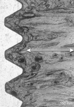
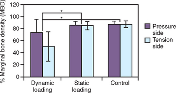
In an animal study using a square thread, microscopic observation noted that when the bone did not fully occupy the threads, greater bone volume was observed on the lower aspect compared with the upper aspect of the square threads (Figure 11-14).46 In addition, a bone bridge was found from one square thread to another. The square thread shape of the tested implants was designed to enhance compression loads and reduce shear loads delivered to the implant interface. Duyck et al. also found in an animal model that the bone density was equally distributed above and below a threaded implant after initial bone healing. However, after dynamic loading, the bone implant density was greater on the bottom of the thread face angle and less on top of the thread (Figure 11-15).47 Kohn and Hollister demonstrated that when the Nobel Biocare Brånemark implant was loaded laterally, a bone bridge formed from the depth of one thread to another (Figure 11-16).48 The local strain field within the bone-implant interface under this condition is inhomogeneous. During a lateral load, the strain was more concentrated at the tip of the thread and the strain was decreased from the exterior to the interior regions of the thread. Kohn and Hollister speculated that because the strains were highest at the tip of each thread, bone was resorbed, and where strains were reduced at the depth of the thread, bone was maintained.

A retrieval report by Bolind et al. confirmed a consistent pattern of BIC location in humans.33 The bone contact was least at the tip of each thread (where the highest strain occurs) and was the greatest under the thread face angle (where the bone is loaded more in compression). Therefore the design of the implant not only governs the initial stability of the implant, but as important determines the BIC percent and location of contact available for effective load transfer to the bone after occlusal loading.
SCIENTIFIC RATIONALE FOR IMPLANT DESIGN
Cortical and trabecular bone are modified by modeling or remodeling.49 Modeling is the result of independent sites of formation and resorption that change the shape or size of bone. Remodeling is a process of resorption and formation at the same site that replaces previously existingbone and is primarily responsible for the change in bone quality. Bone modeling and remodeling are primarily controlled by the mechanical environment of strain.
The histologic description of bone includes lamellar bone, woven bone, composite bone, and bundle bone.50 The first two of these bone types are often found next to an osteointegrated dental implant. Lamellar bone is the most organized, highly mineralized, and strongest of the bone types. It has been called load-bearing bone and is most desired next to an implant. Woven bone also is called immature bone because it is unorganized, less mineralized, and has less strength than the other types. These histologic terms may be used to describe the macroscopic bone types of cortical and trabecular bone.
Nicolella et al. found that a 0.15% deformation in a bone specimen may have microstructural level strain values as large as 3.5% at various regions within the cellular microstructure.51,52 Microstrain levels 100 times less than the ultimate strength of bone may be responsible for remodeling rates within the structure, because the bone cell membranes are able to act as a mechanosensory system in bone.53 In other words, the cellular behavior of bone cells is largely determined by the mechanical environment of strain or deformation of the bone cells.54–56 It is speculated that the source of energy to open the ion membrane channels in the bone cell membrane is the microstrain in the cells as a result of the load applied to the bone.57,58
Frost described four microstrain zones for compact bone and related each of these categories to the mechanical adaptation to strain.59 These four zones include the pathologic overload zone, the mild overload zone, the adapted window, and the acute disuse window. Briefly stated, the pathologic overload zone and the acute disuse window are the two extremes of bone reaction to strain conditions. Each of these conditions, however, may result in a similar condition of less bone. Pathologic overload could lead to microfractures, which require repair and may result in net bone resorption. The disuse zone also increases remodeling, which decreases bone mass (see Figure 7-7).
The remodeling rate, or bone turnover, is the time needed for new bone to replace the existing bone and allows for the adaptation of bone to its environment (e.g., next to a dental implant).60 The bone remodeling rate (BRR) also has been expressed as a percentage or volume of new bone within a specific time period. Lamellar bone forms at a rate of 1 to 5 μm each day, whereas woven bone can form at rates of more than 60 μm each day.61,62 Therefore a higher BRR is directly related to an increase in the amount of woven bone formation. The mild overload zone is more likely to have a higher BRR than the adapted window zone and more reactive woven bone formation (less organized, less mineralized, and weaker) to create and maintain bone mass in response to the mechanical challenge.63 The adapted window zone is most likely to be organized, highly mineralized, lamellar bone. Misch et al. stated the adapted window would be the ideal strain condition next to a dental implant, providing bone that is more mature and more resistant to periodic changes in strain conditions.64 Therefore the BRR may be directly related to the strength of the implant interface and the degree of risk for the implant-bone interface. The higher risk is related to higher turnover rates, because the bone is less mineralized, less organized, and less strong at the interface.
Interface remodeling allows a viable bone interface to form between the dental implant and the original bone after the implant has been surgically inserted.62 Before implant insertion, the bone is usually mature, lamellar bone. The surgical trauma causes the bone to repair, with primarily woven bone formation. By the end of 4 months of a maturation phase next to an implant interface, osteoblasts have deposited about 70% of the mineral found in mature vital bone and have reformed lamellar bone. The remaining 30% of mineral deposition occurs during secondary mineralization over the next 8-month period.50
After the bone has healed and the implant is then loaded, the interface again remodels, as influenced by its local strain environment.49 If woven bone forms as a result of mechanical loading, it is called reactive woven bone and is very similar in structure and properties to the “repair” woven bone from surgical trauma. The long-term maintenance of the implant involves a continuous remodeling of the interface. In part, this allows new bone to replace bone, which may have sustained microfractures or fatigue as a result of cyclical loading. In vivo microdamage in bone and an elevated remodeling activity to repair those regions have been identified by Frost.65 To date, the BRR of the bone in the jaws for humans is not well documented; however, it appears to reach 40% each year.66
Microdamage in cortical bone surrounding screw-type implants has been reported during both insertion and with pullout forces, and the amount of microdamage was related to the thread design of the implants.67 Microdamage acts as a key step in signaling increases in remodeling and replacement of skeletal tissue and is similar to the local tissue remodeling response to physical injury in other tissues.68 Mori and Burr provided evidence of an increased BRR in regions of microfracture from fatigue damage.69 Verborgt et al. found that in the ulnae of rats, fatigue loading produced a large number of terminal dUTP nick-end labeling to detect apoptotic cells (TUNEL)-positive osteocytes in bone surrounding microcracks.70 The intracortical resorption was almost 300% greater than the controls. The authors noted a strong association between microdamage, osteocyte apoptosis, and subsequent bone remodeling. Therefore, in addition to the increased BRR at the interface that is related to the trauma induced during the implant surgery, there may be heightened remodeling of bone some distance beyond the surgical interface after loading. Hoshaw et al. found an increase in bone remodeling next to threaded dental implants in dog tibiae when loaded for 5 consecutive days after a 12-month initial healing period.45 Hoshaw et al. also found titanium threaded implants with axial tensile loading have higher remodeling rates and less mineralized bone than control implants that did not receive a load after healing.71 The increase in the BRR found in the overload zone of Frost and the increase in BRR from the microfracture are directly related.
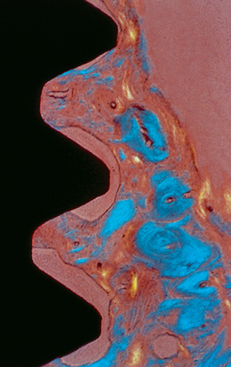
Barbier and Schaper investigated implant-supported prostheses under nonaxial and axial loads.72 A higher cellular response, including osteoblasts and inflammatory cells, was observed next to implants under nonaxial shear loading conditions compared with axial loads (Figure 11-17). These authors stated nonaxially loaded implants exhibited a greater BRR compared with axially loaded implants in animals with the same implant design. It appears the implant design, direction of load, or surface condition may all affect the bone at the implant interface, which affects the bone turnover rate at the interface. Because bone in the jaws usually remodels at 40% per year, this most likely represents the adapted window zone. The higher the BRR, the more likely the bone is in an overload condition.
Thread Geometry
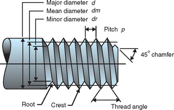
Threads are designed to maximize initial contact, enhance surface area, and facilitate dissipation of loads at the bone-implant interface.38 Functional surface area per unit length of the implant may be modified by varying three geometric thread parameters: thread pitch, thread shape, and thread depth (Figure 11-18).43
Stay updated, free dental videos. Join our Telegram channel
VIDEdental - Online dental courses


