3
ANATOMIC STRUCTURES
To discern a potential problem in the cone beam volumetric imaging (CBVI) data volume, the clinician or radiologist must examine multiple slices in three planes of section: axial, sagittal, and coronal. While clinicians are quite familiar with many structures in the sagittal plane (since it is similar to periapical, bitewing, panoramic, and cephalometric orientations), they are not as familiar with these same structures as viewed in the coronal or especially the axial plane. To illustrate this point, I would ask you to look back at Fig 1-5 and recall the difficulty of interpreting thin slice data in a plane of section most of us have not seen since dental school.
This chapter presents many anatomic structures in the three planes of section as grayscale images, supported in most cases by thicker 3-D slices, slabs, or volume images to help readers orient themselves and recreate the structures in the mind’s eye. No attempt was made to illustrate all structures; the chapter instead focuses on those that are commonly seen by dentists and dental specialists to help them relearn anatomic detail that may be long forgotten. Because many of the structures involve several bones, they are repeated in various views and planes of section.
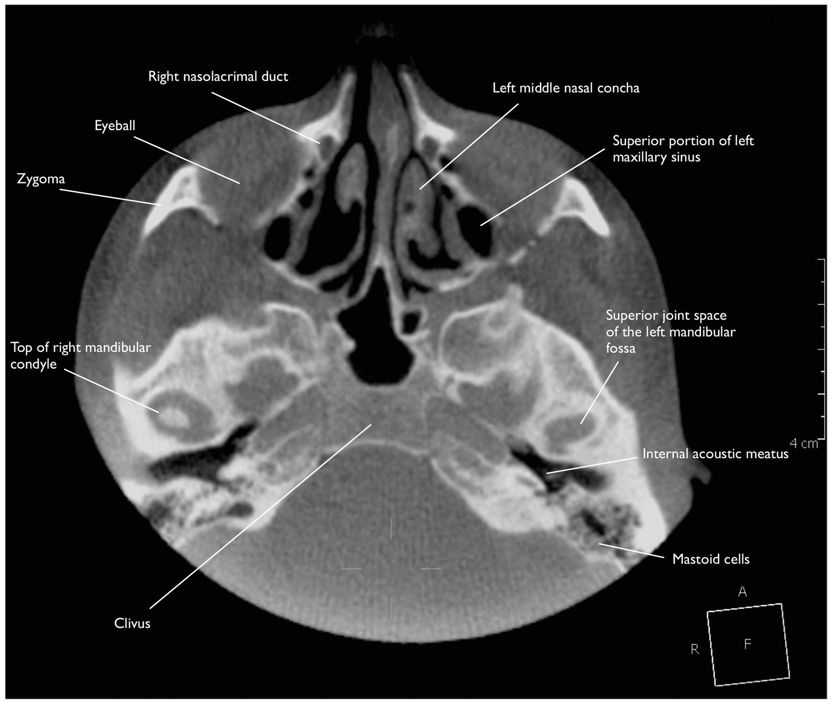
Fig 3-1 A 0.15-mm slice at the level of the mandibular fossa (top of condyle).
MAXILLARY, NASAL, LACRIMAL, PALATINE, AND SPHENOID STRUCTURES
Maxillary structures should be very familiar to all of us, especially in the lateral or sagittal view. Although these bones can be described separately, we will see them in this chapter as they appear clinically—joined together to make walls, spaces, and structures that we must recognize to understand the 3-D changes one might encounter during an examination of a cone beam data volume. When possible, these structures will be identified as they relate to one another.
Structures identified in Figs 3-1 through 3-29 include the antra, incisive foramen and canal, nasal fossa, nasal conchae, nasolacrimal canal, pterygoid plates/processes, pterygoid hamulus, and styloid and mastoid processes. In each section, the structures are identified in the axial plane first (both thin and thick sections), followed by similar views in the sagittal and coronal planes. All three planes appear in Fig 3-29 to show the clinician and student how a specific structure or anomaly is oriented between the three planes. In most instances, the images start with a section through a recognizable part of the anatomy such as the temporomandibular joint (TMJ) condyles.
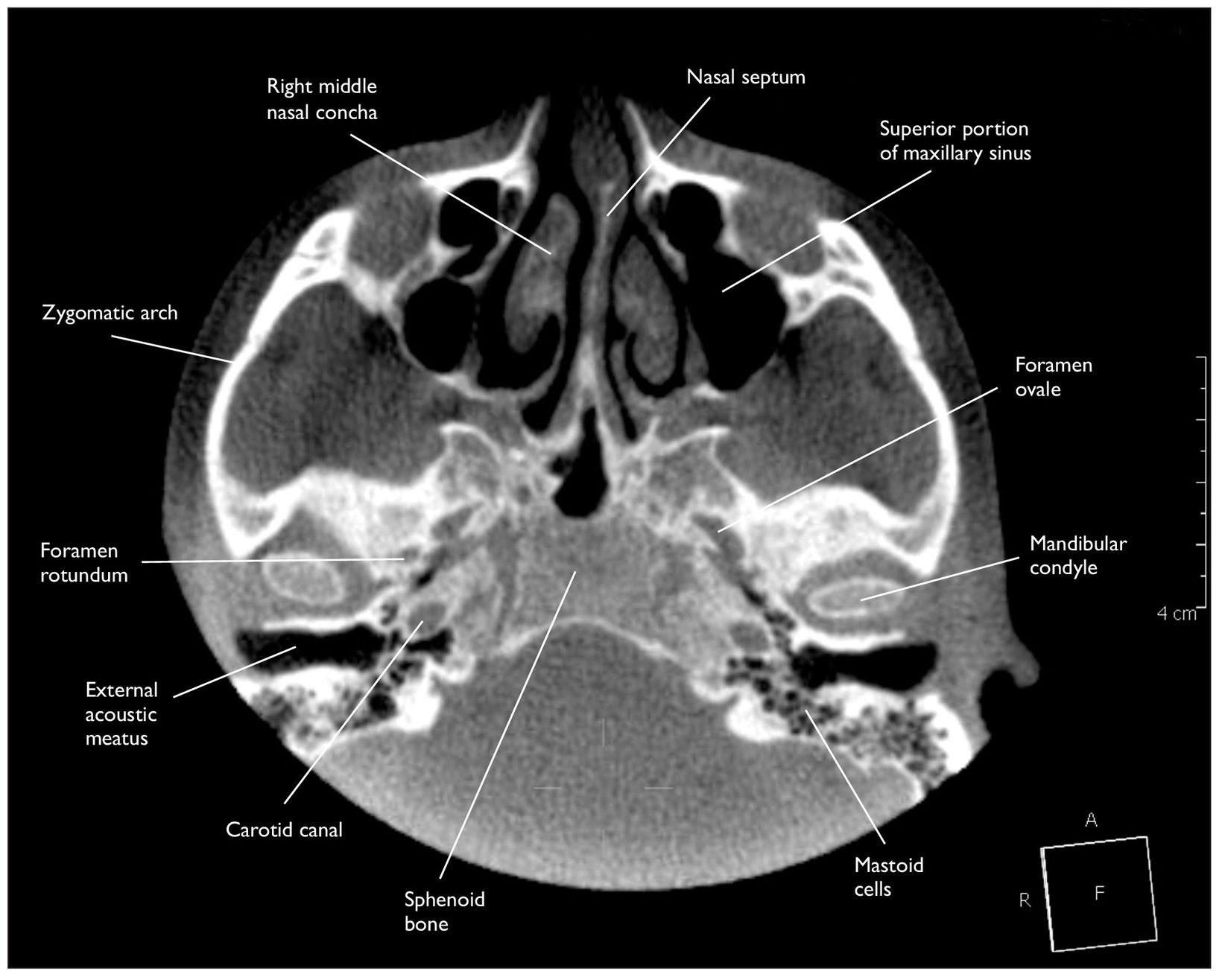
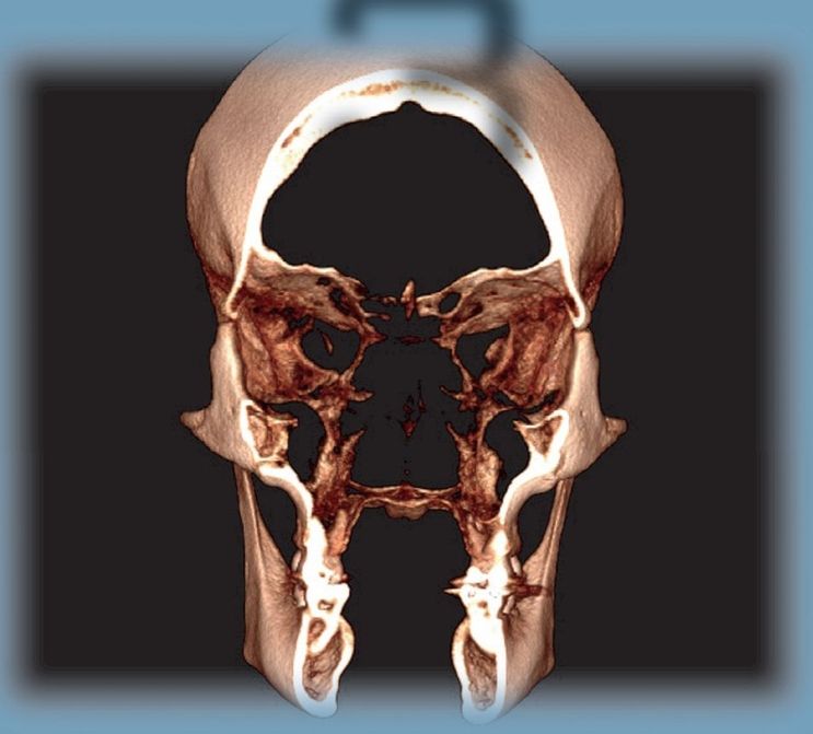
Fig 3-2 A 1-mm slice at the level of the mandibular fossa (middle of condyle).
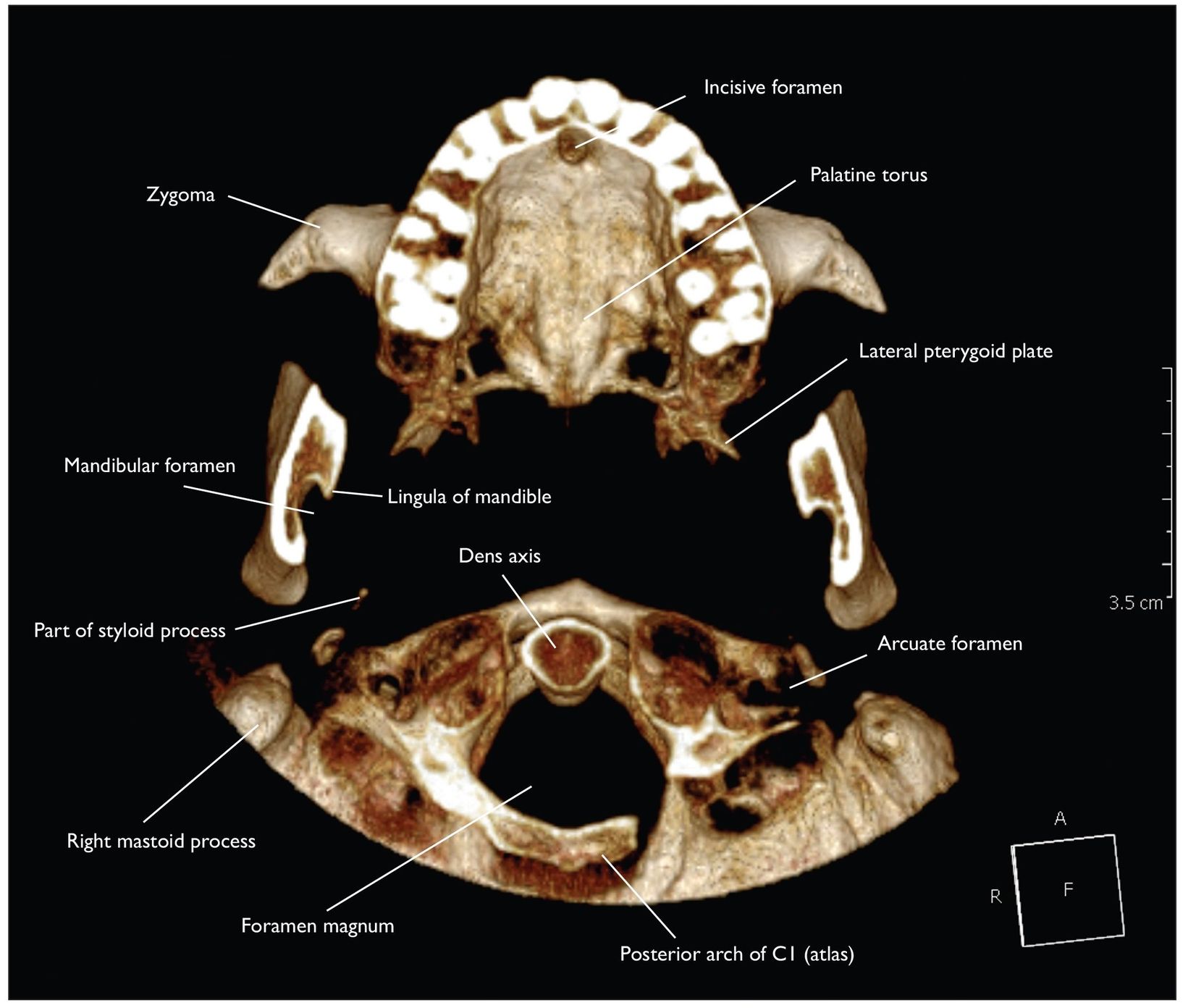
Fig 3-3 A 21.5-mm slice from the palatal to midportion of condyle.
Stay updated, free dental videos. Join our Telegram channel
VIDEdental - Online dental courses


