2
BASIC PRINCIPLES
The method of obtaining the patient’s data volume in cone beam volumetric imaging (CBVI) differs significantly from that of conventional medical computerized tomography (CT). In medical CT scanning (previously termed CAT [computed axial tomography]), the patient’s region of interest (ROI), such as the head or abdomen or other body part, is selected. As the x-ray source rotates around the ROI 60 times per minute, multiple sensors, consisting of either a gas or scintillator material, most commonly cesium iodide (CsI), detect the x-ray beam. The patient must be moved into the scanner a known distance in the z-plane. It is this distance—perhaps a centimeter, a half centimeter, or, in cases where higher resolution is required, as little as one millimeter—that determines the slice thickness. This type of image acquisition is very precise. The data acquired are voluminous and, in turn, the patient’s absorbed x-ray dose is also very large. A typical CT scan for a maxillary implant site assessment may have a radiation dose as high as 2,100 µSv, equivalent to the dose from about 375 panoramic radiographic film or digital images.1
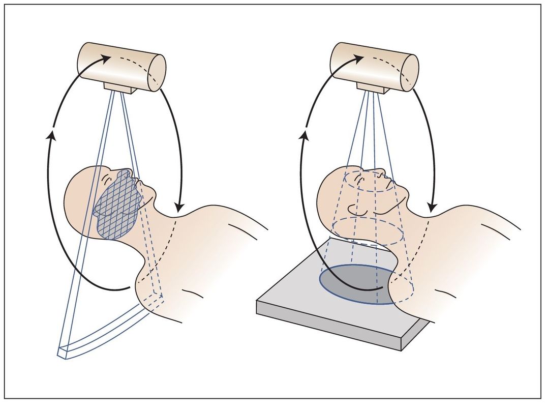
Fig 2-1 (left) A traditional medical CT detector array with x-ray source rotates 360 degrees around the patient about 60 times per minute. The thickness of each image slice is determined by the distance (usually 1.0 mm to 10.0 cm) the patient is moved through the gantry. This exposes the patient to a large dose of x-rays. (right) A cone beam device, using the cone-shaped beam, rotates around the patient. The exposure factors are similar to those used for exposing traditional dental x-rays, so the x-ray dose to the patient is substantially reduced compared to that of traditional medical CT.
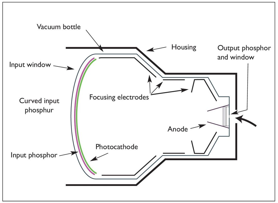
Fig 2-2a In the image intensification (II) system, a curved input phosphor, usually CSI, introduces geometric distortion, which must be compensated for by software.The phosphor coating will degrade overtime, so the II will have to be replaced eventually—sometimes in as few as 3 or 4 years.This older imaging system is being replaced by flat-panel displays, which offer the many advantages of a direct digital capture.
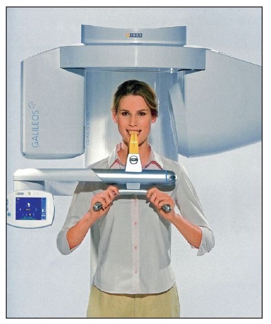
Fig 2-2b This II system is stylish but large because of the II configuration. The x-ray source is on the left of the patient. The detector system is on the right side. (Courtesy of Sirona USA.)
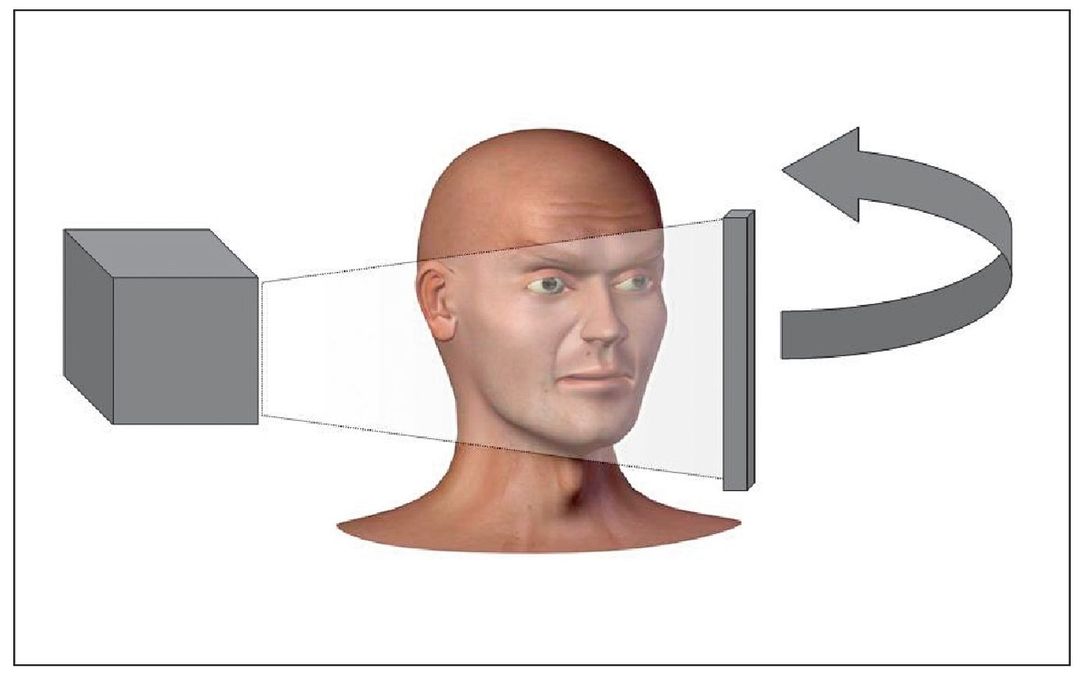
Fig 2-3a The flat-panel detector (FPD) system is a simple digital capture system that uses only an x-ray source and a digital detector to capture the image volume.The devices made with this type of system are much less bulky and therefore more ergonomic.

Fig 2-3b This FPD system is the ProMax 3D (Planmeca USA). (Courtesy of Planmeca USA.)
IMAGE ACQUISITION
Unlike conventional CT, CBVI uses a narrow cone-shaped beam to rotate 194 to 360 degrees around the patient (Fig 2-1). The sensor is either an image intensifier (II) that is coupled to either a charge-coupled device (CCD) (Figs 2-2a and 2-2b) or complementary metal oxide semiconductor (CMOS), or a thin film transistor (TFT) flat-panel type of image receptor (Figs 2-3a/>
Stay updated, free dental videos. Join our Telegram channel
VIDEdental - Online dental courses


