23
Implant Orthodontics: An Interactive Approach to Skeletal Anchorage
Summary
Many types of skeletal anchorage device have evolved in recent years, including dental implants, mini-plates, and micro- and mini-screw implants. The main advantage these devices offer is that the clinicians can move particular teeth in specific directions without causing a reciprocal movement of other dental units. The present chapter discusses the role of micro-implants and their use in interdisciplinary patient management. The ways the orthodontists interact with prosthodontists, periodontists, and oral surgeons in the placement of, as well as in the management of micro-implants are discussed and illustrated with the help of case reports. Vertical holding of molar position, intrusion and uprighting of molars, and forced eruption are discussed in detail along with the associated surgical procedures and their possible complications. The chapter emphasizes the clinician’s need to be knowledgeable about the biological and mechanical principles of orthodontic tooth movement as they pertain to the use of metallic implants, in order to be able to use skeletal anchorage units in a reliable and dependable way.
Introduction
Anchorage preservation is considered to be one of the most important elements of successful orthodontic treatment. Orthodontists have always used a variety of anchorage devices, and almost all have some limitations. Extraoral appliances, which provide reliable anchorage, rely heavily on the patient’s compliance, while all intraoral anchorage devices are associated with some degree of anchorage loss. The introduction of skeletal anchorage in recent decades has changed the scenario, as it provides reliable anchorage that not only does not depend on patient compliance, but also offers great precision in orthodontic tooth movement.
The usefulness of surgical screws in orthodontic anchorage was first demonstrated in a clinical trial by Creekmore and Eklund (1983), who placed a screw into the bone under the anterior nasal spine, in order to provide anchorage for intrusion of maxillary incisors. Kanomi (1997) reported intruding the lower incisors with the aid of 1.2 mm wide surgical screws placed into the mandibular symphysis. Park (1999) placed 1.2 mm wide, 5 mm long micro-screws into the interradicular bone between the maxillary second premolars and the first molars, in order to assist in the retraction of the upper anterior teeth, and demonstrated distalization of the whole maxillary dentition against the micro-screw implant. This report, demonstrating the efficacy of micro-screws as anchorage for retraction of a whole dentition finally changed the orthodontic paradigm from step-by-step tooth movement to en masse group movement (Park et al., 2001; Park and Kwon, 2004), leading to the increased proportion of non-extraction treatment, by molar distalization, in borderline cases (Park et al., 2004a, 2005). The use of skeletal anchorage to intrude the molars to achieve counterclockwise rotation of the mandible decreased the need for orthognathic surgery in the treatment of skeletal open bite (Umemori et al., 1999; Park et al., 2004b, 2006b), with similar skeletal effects.
Many types of skeletal anchorage device have evolved in recent years, including dental implants (Shapiro and Kokich, 1988), mini-plates (Umemori et al., 1999; Sherwood et al., 2002), and mini- or micro-screw implants (Creekmore and Eklund, 1983; Kanomi, 1997; Costa et al., 1998; Park, 1999; Park et al., 2001, 2004a,b, 2005, 2006a,b; Park and Kwon, 2004). Among these devices, the mini- or micro-screw implants have gained increasing popularity because of their small size (which enables placement even in the narrow interradicular bone regions), low cost, suitability for immediate loading, and the ease of the surgical procedure involved in their placement (Park et al., 2001).
The most valuable and attractive contribution of skeletal anchorage, however, has been in pre-prosthetic orthodontic treatment. The teeth in the anchorage/reciprocal part should not be moved during pre-prosthetic orthodontic treatment, in order to avoid any alteration and/or deterioration of the occlusal interdigitation. Because of this requirement, pre-prosthetic treatment with conventional mechanics is quite difficult. To minimize adverse movement in the anchorage/reciprocal part, it has been recommended to include as many teeth as possible in this part of the orthodontic set-up, and to connect the anchor teeth to the teeth on the opposite side of the dental arch for anchorage reinforcement. However, even with all these measures, there is always a certain degree of anchorage loss. With the introduction of skeletal anchorage, it is possible now to bond brackets to a minimal number of teeth, while simultaneously eliminating the adverse reactive movements of teeth (Park, 2009). Consequently, this method is considered to be an efficient way of improving the quality of orthodontic treatment.
Interactive Approaches
As mentioned above, conventional orthodontic treatment mechanics cannot provide precise control of tooth movement and reciprocal anchorage loss tends to compromise the final dental occlusion. However, the skeletal anchorage with micro-implants provides absolute anchorage that allows clinicians to move certain teeth in specific directions without much adverse effects on the rest of the dentition. In other words, the efficiency of micro-implants in controlling tooth position means orthodontists are now capable of moving teeth three-dimensionally, which is highly advantageous for subsequent prosthodontic treatment. Interactive management of pre-prosthetic cases, with close collaboration between orthodontists, prosthodontists, periodontists, and oral surgeons, is thus crucial for the successful outcome of treatment utilizing implant anchorage.
The following discussion and six case presentations demonstrate the ability to use mini-implants as a superior source of anchorage in the treatment of patients with various malocclusions.
Holding the Molar Vertical Position
When dental implants are planned after extraction of posterior teeth, clinicians need to wait for the extraction sockets to heal or until the osseointegration of the dental implant is complete before completing the restoration. However, in the meantime, the antagonist teeth from the opposing arch may extrude. If the teeth on either side of the extracted tooth are in occlusal contact with their antagonists, the tooth with the potential to extrude can be splinted to the antagonists to minimize the extrusive movement. However, in conventional mechanics, where there are several missing or extracted teeth, holding the vertical position is usually accomplished with the help of a temporary denture. This denture might require further modification in the later stages, to remain in concordance with the dental implant placement. This concordance may have adverse effects, compromising the stability of the dental implants. However, with micro-implants, it is possible to prevent extrusion of the molars and hold their vertical position.
Case 1
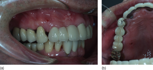
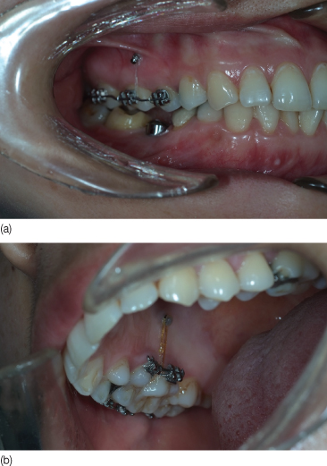
A 47-year-old male patient received dental implants after extraction of the mandibular right molars. During the osseointegration period, the vertical position of maxillary right molars needed to be maintained, that is, the molars need to be prevented from extruding (Figure 23.1). The maxillary molar was positioned in the correct vertical plane, then requiring only maintenance of its position, with the aid of micro-implants. The maxillary right premolars and the second molars were splinted with a 0.019 × 0.025 inch stainless steel sectional wire, and a core composite resin. Two micro-implants (SH1312-08, Absoanchor, Dentos) were placed into the buccal and palatal alveolar bone and ligature wires were lightly tied from the micro-implants to the splint (Figure 23.2) to prevent extrusion of the upper molars. After completion of the implant prostheses in the lower arch, the maxillary appliance were removed (Figure 23.3).
Figure 23.1 Pretreatment photograph showing missing lower right posterior teeth: (a) lateral view; (b) occlusal view.
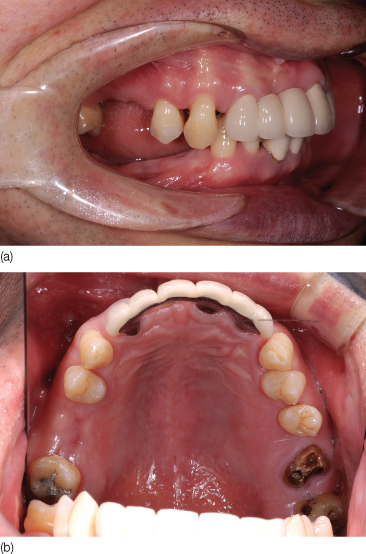
Figure 23.2 A sectional wire was bonded from the premolars to the second molars and ligature wires were tied from the micro-implants to the wire: (a) lateral view; (b) occlusal view.
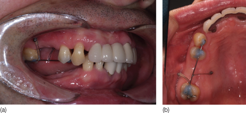
Figure 23.3 Intraoral photographs after insertion of dental prosthesis: (a) lateral view; (b) occlusal view.
Intrusion of Molars
Intrusion of molars is one of the most frequent tooth movements in pre-prosthetic orthodontic treatment. When a molar is missing, the antagonist (molar) tooth tends to extrude and adjacent teeth tip into the extraction space. Before delivering a dental prosthesis, the extruded molar needs to be intruded and the tipped adjacent teeth have to be uprighted. Otherwise, the occlusal surface of the extruded molar will need to reduced. However, reducing occlusal surfaces can result in pulpal exposure or irritation, ending up with a root canal treatment at a later stage.
Conventional orthodontic mechanics for molar intrusion include the use of removable appliances (Alessandri Bonetti and Giunta, 1996) or a bonded lingual intruder (Chun et al., 2000); the success of treatment with removable appliances depends on patient compliance, and the appliance may be dislodged easily. A lingual intruder is bonded to the lingual surface of the teeth and has hooks for applying intrusion force. The appliance is effective, but needs to be bonded to several teeth in order to provide anchorage for the intrusion of one or two molars. In contrast, micro-implant anchorage effectively intrudes molars without any adverse movement of other teeth.
Direction of the Intrusive Orthodontic Force
A vertical orthodontic force should pass through the center of resistance of the tooth that is to be moved to obtain pure intrusion. Otherwise, tipping of the tooth will result in the apices of the dental roots coming into contact with the buccal or lingual cortical plates of the alveolar bone, causing bone fenestrations and root resorption. These consequences appear to be minimal when the amount of intrusion is less than 1 mm.
Magnitude of the Intrusive Orthodontic Force
Diverse opinions exist about the optimal magnitude of the intrusive force. Considering the fact that heavy forces result in root resorption, the application of a light force is desirable. Dellinger (1967) reported that 300 g of intrusion force produced more root resorption than 50 and 100 g in monkeys. Ohmae et al. (2001) reported that root resorption was observed in dogs after loading 150 g intrusion force on the molars. Costopoulos and Nanda (1996) stated that 15 g intrusion force on an anterior tooth resulted in a clinically negligible amount of root resorption in humans. Therefore, it is desirable to use a light intrusion force of about 15–20 g for an anterior tooth and of about 100 g for a molar.
Periodontal Considerations
Control of periodontal as well as gingival inflammation is a prerequisite for safe application of intrusion mechanics. Melsen (1986) showed that after intrusion, the amount of marginal alveolar bone loss on the hygienic side of the dental arch was small compared with the non-hygienic side. Cardaropoli et al. (2001) demonstrated reduction in the size of infrabony pockets after intrusion of teeth, once inflammation was controlled.
Retention of Teeth After Intrusion
Once a prosthetic device has been made in the opposing arch, after intrusion of the extruded teeth, there appears to be no relapse in the tooth movement performed. Until this is done, the micro-implant and the orthodontic appliances should be used as retainers (Park, 2009). If there is a requirement for additional tooth movement buccolingually after intrusion of molars, criss-cross elastics can be prescribed after bonding a lingual button on the prosthesis after its insertion.
Considerations Regarding the Maxillary Sinus
According to earlier reports, the maxillary sinus does not impose limitations on the intrusion of upper molars. One clinical case report showed bone formation around the intruded dental roots while moving a premolar into the sinus in order to develop the site for a prosthetic implant (Re et al., 2001). Similar bone formation around the protruding roots in the nasal cavity was demonstrated in dogs by Daimaruya et al. (2003). However, clinicians have to be cautious about root resorption, which can happen with the application of excessive intrusive forces.
The Effect of Occlusion on Intruded Teeth
Teeth that are intruded may show slight mobility. On the other hand, the dental implant prosthesis in the opposite arch is very firm, that is, it shows no mobility. Occlusal contact of mobile, intruded teeth with the immobile antagonist may cause persistent mobility of the intruded tooth, but this can be prevented by occlusal adjustment.
Intrusion of a Molar with Indirect Anchorage
A simple method of intruding a molar is to apply an intrusive force from the adjacent teeth, which, in turn, are connected to a micro-implant (Figure 23.4).
Figure 23.4 Intrusion of a molar with indirect anchorage. See text for details.
Position of the Micro-Implant
When using indirect anchorage, placement of the micro-implants perpendicular to the bone surface, rather than obliquely, is recommended because of the ease in connecting a sectional wire to a perpendicularly positioned implant. However, in certain cases, in order to prevent root resorption, it is beneficial to position the apex of the micro-implant obliquely at the level of the root apex, where the interradicular space is wider.
Micro-implants can be placed either on the buccal or the palatal side of the alveolar bone. The buccal side provides easier access for surgical placement. On the contrary, the palatal side has wider interradicular spaces and a larger amount of masticatory mucosa, which is more resistant to inflammation. However, the palatal side has poor accessibility and a palatal micro-implant causes tongue irritation.
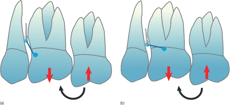
Biomechanical Considerations
When using the micro-implant as indirect anchorage for molar intrusion, the sectional wire connecting the micro-implant to the anchor tooth should be aligned as vertically as possible to be able to resist the reactive extrusive forces and moment on the anchor tooth (Figure 23.5a). If the sectional wire is horizontally aligned, the rotational moment exerted on the anchor tooth will be larger (Figure 23.5b) than when it is aligned vertically. As the micro-implants has weak resistance against torsional or rotational forces (Costa et al., 1998), the sectional wire should be connected parallel to the reaction force so that only a pushing or pulling force is loaded on the micro-implant. Thus the position of the micro-implant should be decided bearing this consideration in mind.
Figure 23.5 A vertically connected wire (a) from micro-implant to an anchor tooth can resist better than a horizontally connected wire (b).
(Printed with permission, from Park [2009].)
Case 2
A 50-year-old male patient presented with extruded maxillary second and third molars, a situation that had developed following the loss of the mandibular second molar (Figure 23.6). We decided to extract the maxillary third molar and to intrude the maxillary second molar to providing vertical space for a mandibular prosthesis. A micro-implant (SH1312-08, Absoanchor) was placed into the buccal alveolar bone between the maxillary second premolar and the first molar (Figure 23.7). A 0.016 × 0.022 inch stainless steel sectional wire was fabricated and attached with core composite (Bisfil Core, BISCO Inc.) to the second premolar, the first molar, and the head of the micro-implant (Figure 23.8). Standard 0.018 × 0.022 inch slot brackets were bonded on the buccal surfaces of the maxillary first and second molars, and to the palatal surfaces of the second premolar and molars. Sectional titanium-molybdenum (TMA) wires, 0.016 × 0.022 inch, were fabricated and ligated to apply intrusion force with an activation of 0.5 mm. Note that the application of force on both sides, buccal and palatal, minimizes the tipping of the molar buccolingually (Figure 23.9). The irritation caused to the tongue by the brackets on the palatal surface can be alleviated by use of wax or silicone periodontal wound dressing (e.g. Barricaid R, Dentsply-Gendex). The appropriate intrusion was achieved after 5 months of treatment (Figures 23.10, 23.11). The same orthodontic appliance was used as a retainer while waiting for osseointegration of the lower dental implant and prosthesis. After the delivery of the dental prosthesis in the lower arch, all the appliances were removed (Figures 23.12, 23.13). As it takes 5–6 months to intrude a molar by 2–3 mm and osseointegration requires 3–6 months, to reduce the treatment time, the clinicians can perform intrusion of the upper molar and the lower dental implant placement in the same time period.
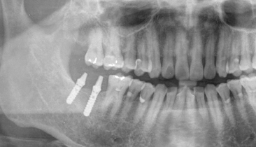
Figure 23.6 Panoramic radiograph showing the extruded maxillary right second and third molars.
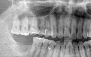
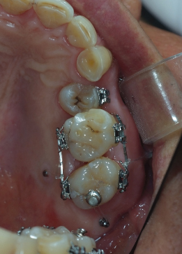
Figure 23.7 Micro-implant placed in the alveolar bone between the second premolar and first molar.
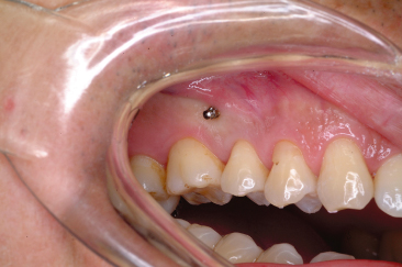
Figure 23.8 Sectional wire connected from the micro-implant to the teeth.
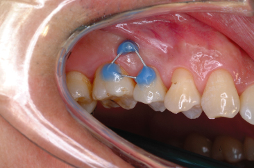
Figure 23.9 Brackets bonded on the buccal and palatal surfaces to apply intrusion force from both sides: (a) lateral view; (b) occlusal view.
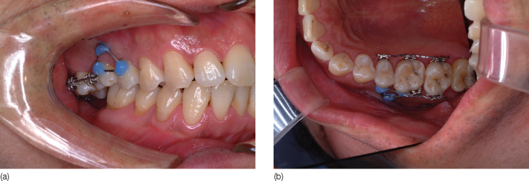
Figure 23.10 At 5 months of treatment, the second molar was intruded: (a) lateral view; (b) palatal view.
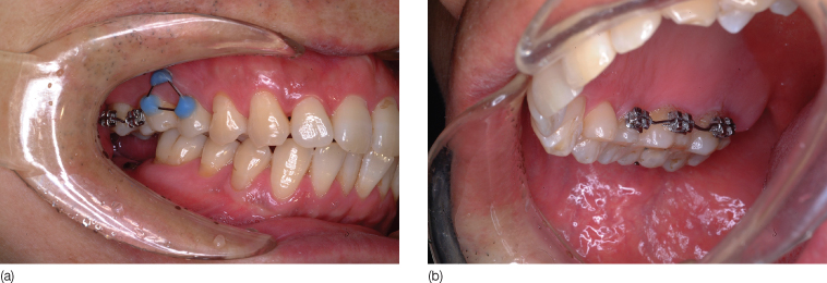
Figure 23.11 Panoramic view showing the intrusion.
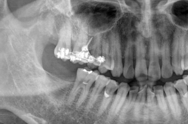
Figure 23.12 Post-treatment intraoral photographs: (a) buccal view; (b) palatal view.
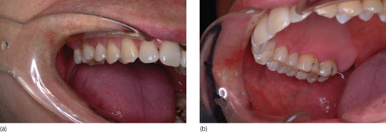
Figure 23.13 Post-treatment panoramic radiograph.
Simultaneous Intrusion of Two Molars
One of the easy and biomechanically simple methods of intruding two molars on one side of the dental arch is to use buccal and palatal micro-implants. Tooth movement stops when the root contacts the micro-implant during intrusion. To avoid this contact, the micro-implant is placed in the apical area so that there is enough space between the micro-implant and the roots for their subsequent movement. Since the buccal interradicular space between the upper first and second molars is narrow (Park et al., 2010), micro-implants should be placed in the apical area where the space is relatively wider. Since maxillary molars have a single palatal root, there exists a wide space for the micro-implant on this side, and since the buccal root curves distally, the micro-implant needs to be inserted distal to the contact point.
In addition, to maintain the curve of Spee, the second molar should be located higher than the first molar and needs to be intruded to a greater extent. The direction of the orthodontic force depends on the position of the head of the micro-implant and the attachment on the tooth. To obtain greater intrusion of the second molar, the micro-implant should be placed distal to the contact point of the first and second molars (Figure 23.14), or occasionally, an additional micro-implant in the maxillary tuberosity can be helpful (Figure 23.15).
Figure 23.14 The micro-implant is placed distal to the contact point to provide a greater intrusive force for the second molar.
(Printed with permission, from Park [2009].)
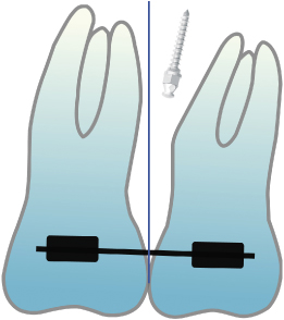
Figure 23.15 An additional micro-implant placed into the maxillary tuberosity produces a distal intrusion force to achieve greater intrusion of the second molar.
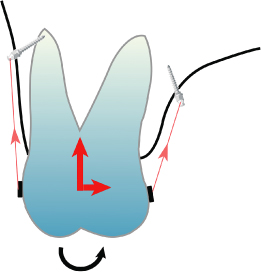
Owing to the weaker alveolar bone on the palatal side, which is covered by thick soft tissue, the distance from the buccopalatal midpoint of the tooth crowns to the head of the micro-implant should be greater on the palatal side than on the buccal side. The resultant horizontal component of force on the palatal side will, therefore, be stronger than on the buccal side (Figure 23.16) resulting in palatal tipping of the molar. To prevent this tipping, the buccal micro-implant should be long, and at the same time it should protrude buccally, while the palatal micro-implant should be inserted close to the gingival margin, thus reducing the horizontal component of force. The alignment of teeth can also be performed during the intrusion by bonding brackets and adding appropriate bends to the sectional wires. Sectional wires can be bonded directly to the tooth surfaces if there is no such requirement.
Figure 23.16 Palatal tipping of intruding molar occurs when the distance from the micro-implant to the midpoint of the teeth on palatal side is longer than on the buccal side.
(Printed with permission, from Park [2009].)
Case 3
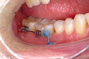
A 38-year-old female patient attended the orthodontic clinic with a supraerupted maxillary right second premolar and first molar, following the loss of the mandibular first molar (Figure 23.17). Two micro-implants (buccal: SH1312-08, palatal: SH1312-10) were placed into the buccal and palatal alveolar bone between the second premolar and the first molar (Figure 23.18). In order to provide sufficient space for intrusion, the buccal micro-implant was placed high into the vestibule. The heads of the micro-implants on the buccal and palatal sides were located at the same distance from the midpoint of the crowns buccopalatally, to minimize tipping of the teeth in this plane (Figure 23.19). Standard 0.018 × 0.022 inch brackets were bonded to the buccal and palatal surfaces of the second premolar and first molar. Sectional TMA wires, 0.016 × 0.022 inch, were ligated and intrusive forces applied from the micro-implants to the wires (Figure 23.20). To reduce the treatment time, an intrusive force is usually applied immediately after insertion of the micro-implants. We prefer to use elastomeric threads such as Super thread (RMO) or Square thread (Dentos) for this purpose. These produce relatively light force, and the Square thread has the advantage of minimal food impaction. After 5 months of treatment, the second premolar and the first molar were intruded to the level of the second molar (Figure 23.21). After bonding a bracket to the second molar, further intrusion forces were applied to all three teeth. After 8 months of treatment, all three teeth showed an appropriate amount of intrusion (Figure 23.22). After attachment of the prosthesis to the lower arch, the upper appliances were removed (Figure 23.23).
Figure 23.17 Supraerupted upper right second premolar and first molar.
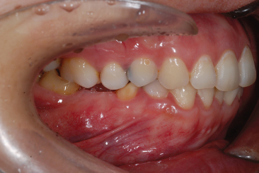
Figure 23.18 Micro-implants placed in the buccal (a) and palatal (b) alveolar bone.
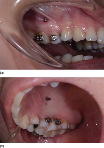
Figure 23.19 Occlusal photograph showing the same distance from the micro-implants to the midpoint of teeth on buccal and palatal sides.
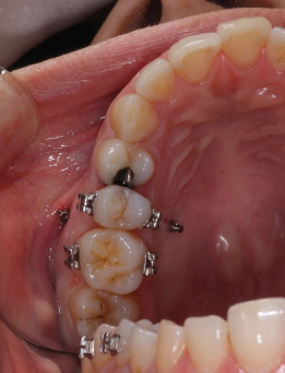
Figure 23.20 Intrusive force applied from the micro-implants to the wire: (a) buccal view; (b) palatal view.
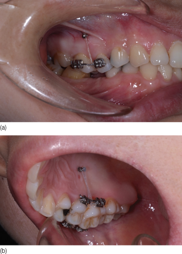
Figure 23.21 Intrusion achieved at 5 months of treatment: (a) buccal view; (b) palatal view.
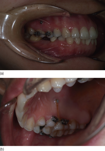
Figure 23.22 Intrusion achieved at 8 months of treatment of three teeth (now including the second molar): (a) buccal view; (b) palatal view.
Stay updated, free dental videos. Join our Telegram channel
VIDEdental - Online dental courses


