Restoration of Acquired Oral Defects with Osseointegrated Implants
John Beumer, III1, Karl Lyons2, Jay Jayanetti1, and Eric C. Sung1
1 University of California, Los Angeles School of Dentistry, Los Angeles, California, USA
2 University of Otago, Dunedin, New Zealand
Introduction
Treatment of tumors of the oral cavity may result in severe functional disability and cosmetic disfigurement. Not so long ago, it was difficult to rehabilitate these patients on a consistent basis. Today, however, it is possible to restore most patients to near normal form and function, enabling them to lead useful and productive lives. Two advances have made this possible and both were introduced in the 1980s: osseointegrated implants and free vascularized flaps. Implants permitted the prosthodontist to provide additional stability, retention, and support for our intraoral prostheses, and free flaps enabled the surgeon to reconstruct oral tissues, such as the mandible and the tongue, on a consistent basis. Implants have also been a valuable tool for restoring patients presenting with traumatic and congenital defects.
Implant‐retained prostheses for acquired hard and soft palate defects
Prosthetic rehabilitation is still the primary and the preferred means of restoring acquired defects of the hard and soft palate following tumor ablation. These prostheses are used to restore the partition between the oral and nasal cavities, restore the palatal contours and the missing dentition, and enable normal velopharyngeal function, permitting the patient to speak and swallow normally. In experienced hands, the clinical outcomes are quite predictable. The principle challenge, especially in edentulous patients, is retention of the prosthesis.
Restoration of hard palate defects
Retention provided by osseointegrated implants can have a dramatic effect on the function of the prosthesis, especially for the edentulous maxillectomy and palatectomy patient (Figure 21.1). Implants are equally impacting for edentulous patients presenting with soft palate defects because the implants retain and precisely position the complete denture–obturator in the velopharyngeal area and permit it to interact effectively with the residual velopharyngeal musculature (Figure 21.2). They have also been used with success in patients with hard and soft palate defects with marginal or failing residual dentition. Implants provide retention, enhance support, and improve the stability of the obturator prosthesis. Mastication performance may be restored to presurgical levels in some patients2 and, with the retention provided by the implants, the obturator prosthesis restores speech and swallowing to normal limits.
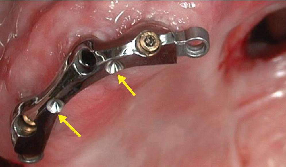
Figure 21.1 Implant connecting bar used to retain a complete denture–obturator in an edentulous maxillectomy patient. Note the rests atop the implant connecting bar.
Source: Beumer et al., 2011.1 Reproduced with permission from Quintessence Publishing Company Inc.
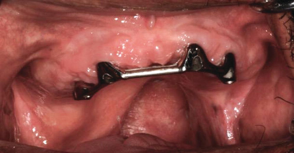
Figure 21.2 Implant connecting bar used to retain a complete denture and soft palate obturator in a patient with a soft palate defect.
Clinical data
Previous studies3–5 describe the locations and prognosis for implants used to support and retain maxillary obturator prostheses. In the Roumanas report,3 102 implants were placed in 26 patients with acquired maxillary defects secondary to resection of palatal and paranasal sinus tumors. Seventy‐eight implants with known status were available for study. The implant survival rate for these 78 implants was 69.2%. The implant survival rates were 63.6% for the irradiated group (67.0% before radiation and 50% after radiation, mean dose of 50 Gy) and 82.6% for the nonirradiated group.
A pattern of failure and bone loss was apparent with implants placed in each of the three most common sites. Failures were grouped into two categories: namely early, when the implants failed to achieve osseointegration within 6 months and following the second‐stage surgery, and late, when implants failed after being subjected to clinical function for a year or more. Minimum bone loss was defined as bone loss limited to 1–2 threads, moderate 3–4 threads, and severe more than 4 threads. In the anterior maxilla three failures occurred “late” and were secondary to progressive bone loss around the implants. Almost one half of the implants in the premaxilla currently in function demonstrated severe bone loss. In contrast, in the maxillary tuberosity where the bone quality is generally poorer, virtually all of the implant failures were “early” or prior to functional loading. However, once osseointegration was achieved and the implants were placed into function, bone levels did not appear to deteriorate over time. The Roumanas report3 and animal studies6–13 suggest that implant overload was responsible for the pattern of bone loss and implant failure in these patients. These data prompted a significant change in the design of implant connecting bar.
The implant connecting bar attachment system initially used at UCLA, when implants were clustered in the residual anterior maxillary segment, employed a “Hader” bar extension posteriorly on the unresected side. This implant connecting bar‐attachment system did not accommodate for the multiple axes of rotation and forces applied to the implants associated with bolus manipulation, mastication, and eccentric mandibular movements. Chewing forces on the unresected side resulted in significant load magnification of the distal implant because of the cantilevering effect. Thus, this may be the primary reason why so many of the implants placed into the premaxillary segment quickly demonstrated advanced bone loss. In large defects or where only tuberosities remain (Figure 21.3), single implants with “O” ring attachments were used. The solitary implants with an “O” ring attachment permit multiple axes of rotation and so the implants were used almost entirely for retention as opposed to providing support and/or stability. As a result the torquing forces delivered to the implant were limited.
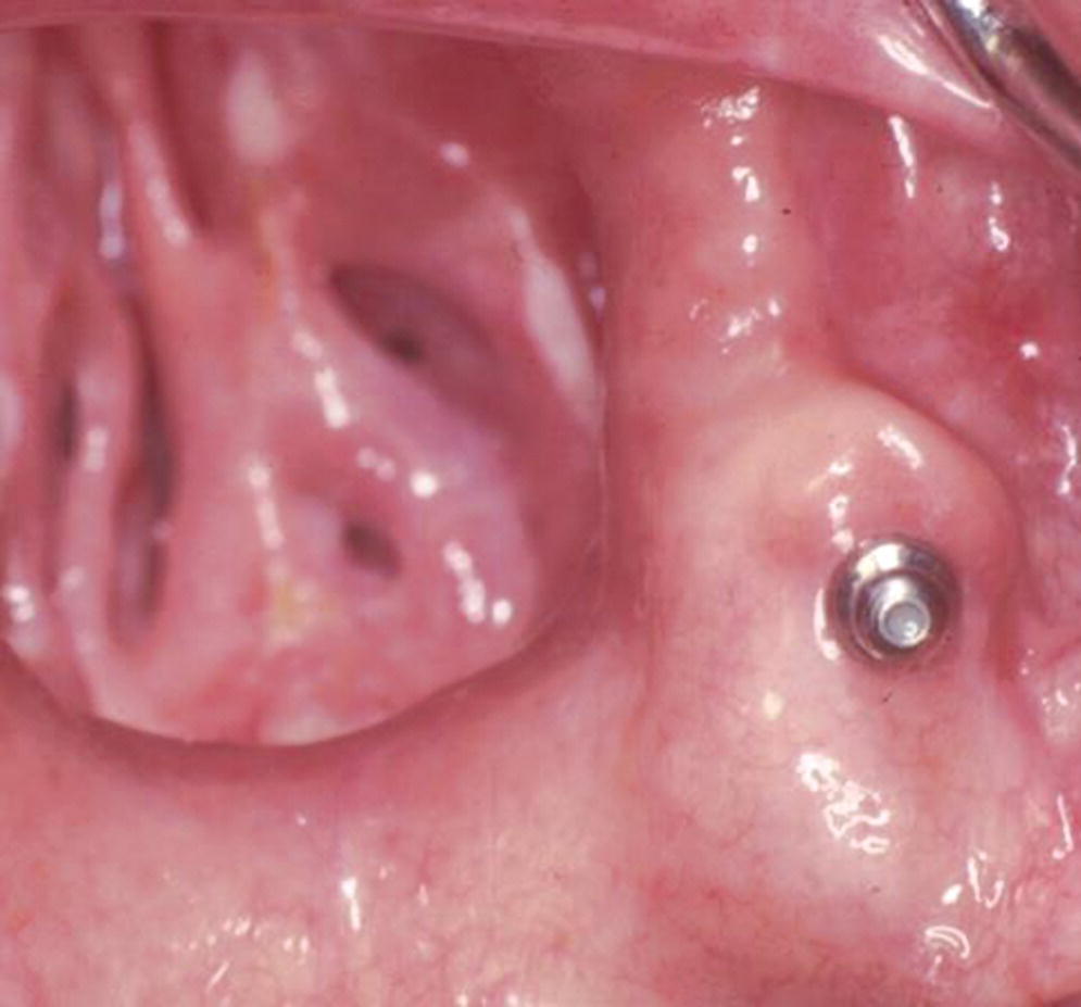
Figure 21.3 Single implant with “O” ring attachment used to retain a large obturator. “O” ring allows prosthesis to rotate around multiple axes.
Implant sites
The number of implants and their location is determined by the nature of the defect and the available bony sites. The ideal location for implants for most edentulous total maxillectomy patients is the residual premaxillary segment (Figure 21.1). This site is preferred because the anterior maxillary segment is opposite the most retentive portion of the classical skin‐lined radical maxillectomy defect, located along its posterior lateral wall. In addition, satisfactory volume and density of bone can be found in the premaxilla in most patients. The maxillary tuberosity site (Figure 21.3) is considered only when there is insufficient bone in the residual premaxilla. Since the bone is not very dense in the maxillary tuberosity, initial implant stabilization is difficult, as evidenced by the high failure rates at stage II surgery. Because of this factor, some clinicians have recommended placing longer, mesially inclined implants in this region. The edentulous posterior alveolar process may serve as an alternative site for implants if there is at least 10 mm of bone available beneath the maxillary sinus. If insufficient bone is present, these sites may be augmented by sinus augmentation.14,15 This technique has become a popular option when treating conventional patients, but has also been used in patients with large hard palate defects.1
Implants of conventional lengths have been used in the residual elements of the zygoma on the defect side of total maxillectomy defects.1 However, there are important disadvantages to be considered with this approach. First, it is very difficult surgically to create a zone of immobile tissues around the implants. Second, the implants will exit the tissues high in the defect, making oral hygiene very difficult for the patient. As a result, the risk of peri‐implantitis is very high. Third, because the implants are generally positioned parallel to the plane of occlusion they cannot be engaged aggressively. Magnets are often used to minimize lateral torquing forces delivered to the implants. In the authors’ limited experience, most implants of conventional lengths used in this site have failed. In defects lined with a skin graft with good posterior lateral undercuts, these implants make only a limited contribution to retention.
Zygomatic implants 20–30 mm long, however, have been used effectively in patients with large maxillectomy or total palatectomy defects. In the UCSF report,16 28 zygomatic implants were placed in nine patients with large maxillary defects. Six implants failed (most in irradiated patients), and five of the patients were eventually restored with an implant‐retained obturator prosthesis.
Landis et al.,17 reported the use of 36 zygomatic implants in 15 patients. Twenty‐four conventional implants were also placed in oral sites in these patients. Twelve of the 15 patients presented status post resection of large tumors of the maxilla and three presented with congenital defects. Nine of the patients were edentulous. Six of the twelve oncology patients received chemotherapy and seven received radiation therapy during the course of their treatments. Radiation doses ranged from 45–61 Gy. Nine of the patients were edentulous. The prostheses were retained with telescopic crowns associated with, when necessary, angled abutments. Follow‐up ranged from 13–102 months. Three zygomatic implants were lost secondary to overloading and/or chronic infection and five others were removed secondary to resection of recurrent neoplastic disease.
When restoring total palatectomy defects the authors recommend that, when possible, two implants be placed into each residual zygoma (Figure 21.4) and that all implants be splinted together with an implant connecting bar (Figure 21.5).
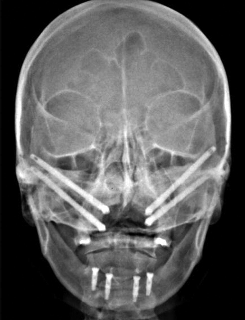
Figure 21.4 When possible two implants should be placed into each zygoma.
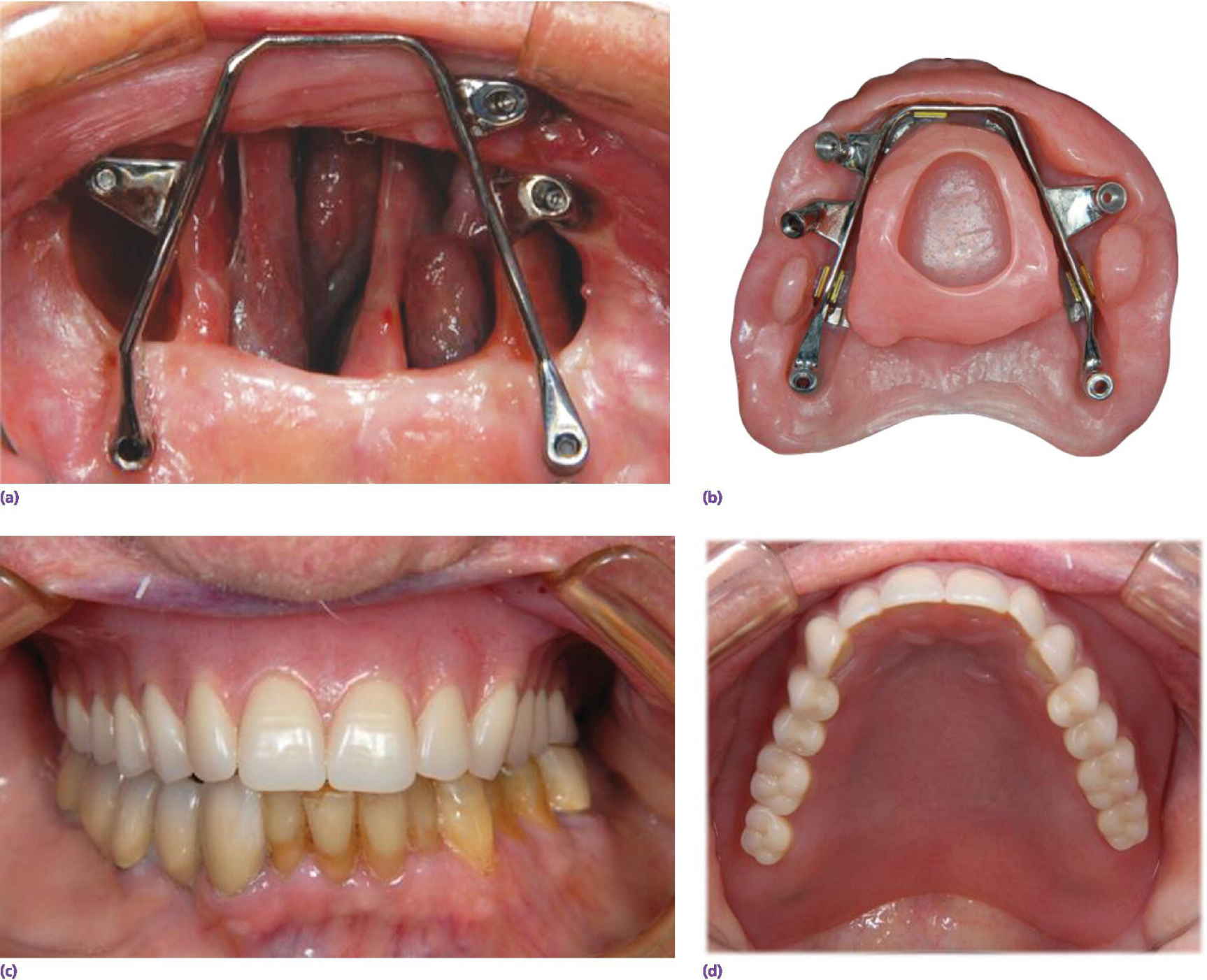
Figure 21.5 (a) A total palectomy defect restored with combination of tuberosity/pterygoid implants and zygomatic implants. (b) Obturator bar with implant connecting bar. (c, d) Prosthesis in place.
Clinical procedures
Following implant placement, the implants are left to heal for several months before they are exposed to functional forces. During this period the patient continues to function with the existing obturator prosthesis. When the implants are exposed at second‐stage surgery, the surgeon should carefully thin the mucoperiosteum and create a zone of keratinized, attached mucosa around the implants. If the implants exit in mobile, unattached tissues, an attempt should be made to replace these tissues with keratinized attached tissues. Free grafts from the palatal mucosa are preferred to skin grafts.
Fabrication of the definitive obturator prosthesis begins when the peri‐implant soft tissues are well healed. It is desirable to fabricate a trial denture before designing the retention apparatus. The authors prefer to splint multiple implants together with implant‐assisted implant connecting bars as opposed to the use of individual attachments. Preliminary impressions are made with transfer (closed tray) impression copings. An edentulous stock tray is chosen and the defect portion of the tray augmented with periphery wax. The impression is made with irreversible hydrocolloid material. Care should be taken to record the lateral wall of the defect and any desirable undercuts which may be engaged by the definitive prosthesis. Following removal of the impression, the impression copings are removed, attached to fixture analogs as required, and inserted into the impression. A preliminary cast is poured with dental stone.
The custom tray for the master impression is designed to record the position and angulation of the implants, as well as the residual normal tissues and those associated with the palatal defect. When the border molding is completed, pick‐up type impression copings are secured tightly in position, linked with pattern resin, and an elastic impression material is used to modify the impression. When the impression material has polymerized, the screws securing the copings to the implant fixture are loosened and the impression is removed. Fixture analogs are then attached to the impression copings imbedded in the impression, and the impression is boxed and the master cast prepared in the usual manner.
Record bases are now fabricated. Healing abutments of the same length and diameter as those used in the patient are attached to the implant analogs and a record base is fabricated with autopolymerizing acrylic resin. The record base should positively engage these healing abutments as well as the lateral wall of the skin‐lined maxillary defect. This technique will maximize the stability and retention of the record base used to make maxillo‐mandibular registrations. A face bow transfer record is obtained and transferred to an articulator that will accept the large maxillary cast.1 The centric relation record is secured and the opposing mandibular cast is mounted on the articulator.
The anterior teeth are selected and arranged using established criteria and the posterior teeth are selected and arranged according to neutro‐centric occlusal concepts. The waxed trial dentures are tried in the mouth, and the centric relation record and occlusal vertical dimension are verified. The anterior teeth are evaluated for acceptable speech and esthetics. The trial dentures are repositioned on the articulator and a silicone template is fabricated with the maxillary teeth incorporated within it. Detailed descriptions of these procedures can be found elsewhere.1
Design of the implant connecting bar and fabrication of the prostheses
The authors prefer implant‐assisted implant connecting bar designs for this group of patients. In such designs the primary support is derived from the residual denture‐bearing surfaces and key areas of the defect. The implants are used to facilitate stability and retention of the large obturator prosthesis. The authors prefer to unite the implants with a rigid, precision‐fitted implant connecting bar with retentive elements attached to the bar. The potentially most damaging forces on implants will result from occlusal loading and so, ideally, the bar‐attachment apparatus should be designed to direct most occlusal forces along the long axis of the implant fixtures. The implant connecting bar should be designed so that posterior occlusal forces are borne by the residual alveolar ridge and maxillary tuberosity as opposed to the implants. Gravitational forces are much less of a concern and can be reduced by aggressively engaging undercuts and the lateral wall of the maxillary defect. In large defects, lateral forces secondary to lateral displacement of a large obturator prosthesis need to be taken into account.
Numerous factors complicate the design of the bar and the distribution of occlusal forces for total maxillectomy patients. For example, when the patient is subjected to a radical maxillectomy (resection of half of the hard palate), fewer implant sites are available and the anterior–posterior (AP) spread of the implants placed in the remaining edentulous premaxilla is often limited. In addition, occlusal loads produce multiple axes of rotation of the obturator prosthesis, especially when the food bolus is excised anteriorly on the side of the defect. These axes are dependent upon the position of the implants and the point of load application on the prosthesis.
Davis et al.,18 developed a photo‐elastic model to determine the most favorable implant connecting bar‐attachment design when implants were placed in the residual premaxilla following a radical maxillectomy. A photo‐elastic model was fabricated that was based on a human maxilla that had undergone a radical maxillectomy. Photo‐elastic materials were used to simulate the bone around the implants and the bone along the medial and lateral aspects of the defect. Three implants were used on the nondefect side to simulate a common clinical situation and bar designs were fabricated with a gold alloy, duplicating various clinical conditions. The following designs were tested:
- implant connecting bar with Hader clips placed to the mesial of the anterior implant and distal to the posterior implant;
- implant connecting bar with ERA (APMS, Stern Gold, Attleboro, MA) attachments placed to the mesial of the anterior implant and distal to the posterior implant;
- implant connecting bar with ERA attachments placed to the mesial of the anterior implant and distal to the posterior implants, with occlusal rests between each of the implants;
- implant connecting bar with “O” ring (Attachments International, San Mateo, CA) attachments placed between the implants;
- implant connecting bar with an ERA attachment placed to the mesial of the anterior implant and a Hader clip distal to the posterior implant;
- implant connecting bar with an OSO attachment placed on the anterior and posterior implants.
The acrylic resin obturator extension base was fabricated and the loading regions selected for testing were anterior and posterior to the implants. Each loading zone had a ramp so that a force of 5.44 kg (12 lb) could be applied in both a vertical and lateral direction at each location. The photo‐elastic cast was firmly fixed to the base of the stage of a straining frame. A force of 90 g was applied to the acrylic resin extension base to correspond to the weight of the obturator. Circularly polarized light was used to illuminate the cast and the results were recorded photographically. The stress patterns developed by the different designs were compared by placing them on the cast without exerting any type of external load. The resulting stresses were observed and recorded with a camera having an appropriately oriented set of polarized and quarter‐waved plates affixed to the lens.
The most pertinent conclusions of the study were as follows:
- anterior loads caused higher and more concentrated stresses around the anterior and middle implants as compared to posterior loads, since posterior loads are partially supported by the residual edentulous denture‐bearing surfaces;
- the addition of occlusal rests on the bars between the implants increased the stability of the prostheses and alleviated the stresses around the posterior implant when a posterior force was applied;
- the “O” ring type attachment resulted in the most favorable stress distribution as compared to the bar–clip or the bar–ERA designs. However, the “O” ring designs were not as retentive as the other attachment systems tested.
Davis and her colleagues18 concluded that bar design is a compromise between retention and the need for stress distribution and maintenance of the bone around the implants. Based on this work and our clinical experience,2 the authors propose the following guidelines. With the use of a resilient attachment like the ERA, which allows for a vertical compression of the prosthesis in the edentulous extension areas upon application of an occlusal load, the addition of occlusal rests improves the distribution of stresses. For example, when a load is applied to point #1, the prosthesis will rotate around the new axis AB, which passes through the distal occlusal rest (Figure 21.6). Most of the occlusal load is absorbed by the residual denture‐bearing surfaces in the posterior denture extension areas, and these forces are directed more favorably along the long axis of the implants. The ERA attachments allow the prosthesis to be compressed into the bearing surfaces, but provide retention when dislodging forces are applied. The implant connecting bar provides stability for the prosthesis. The placement of rests at either end of the bar enables the prosthesis to rotate around these rests, reduces wear on the attachments, and directs more of the occlusal forces along the long axes of the implants. This design has been used with success at UCLA since the mid 1990s. These design principles are similar to those proposed by Kratochvil,19 for class I or class II distal extension removable partial dentures using the “I” bar, mesial rest concept. The patient should be advised against applying occlusal forces posteriorly on the defect side, since there is little support available to counteract these forces. Forceful occlusion on the defect side will result in rapid wear of the attachments and subsequent bone loss around the implant adjacent to the defect.
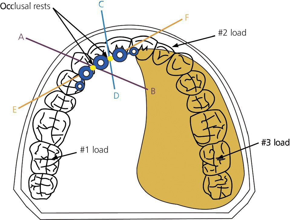
Figure 21.6 “ERA” attachments attached to each side and occlusal rests placed on top of bar. Rests on metal framework control axis of rotation and allow “ERA” attachments to function as designed.
Source: Beumer et al., 2011.15 Reproduced with permission from Quintessence Publishing Company Inc.
If the entire premaxilla remains, the number of implants, their distribution, and the design of retention bar follow more conventional prosthodontic guidelines. Under these circumstances we prefer that four implants be placed and suggest the design shown in Figure 21.2; see also Figure 21.9. The use of tilted implants in the posterior positions will increase the AP spread and improve biomechanics.20–22 In this design the support is provided posteriorly by the residual denture‐bearing surfaces and anteriorly by the implants. This design is particularly well suited for combination hard palate–soft palate defects. The attachments connected to the distal portion of the bar are resilient and allow for compression of the mucoperiosteum of the distal extension area engaged by the prosthesis, limiting the torquing forces applied to the implants.
Anterior maxillary defects, or large maxillary defects where only one or both maxillary tuberosities remain, are especially difficult to restore. Implants are useful in retaining these restorations but they should not be the primary means of support. Resilient type attachments are preferred, using the design principles described above (Figure 21.7). If only a single implant is available, an “O” ring type attachment is preferred, because they allow the prosthesis to rotate in multiple directions when either an occlusal load is delivered, when the prosthesis drops as a result of gravity, or when it is displaced in the horizontal plane by the facial musculature or eccentric mandibular movements (Figure 21.3).

Figure 21.7 Suggested implant connecting bar design used to retain overdentures with soft palate obturators. (a) Note position of implants. Anterior–posterior spread should be maximized. Resilient attachments provide retention and the anterior segment of the bar provides indirect retention and support. (b) During mastication the anterior segment of the implant connecting bar serves as an axis of rotation and resilient attachments allow the posterior denture‐bearing areas to support occlusal forces.
Source: Beumer et al., 2015.23 Reproduced with permission from Quintessence Publishing Company Inc.
(c) Typical patient with a soft palate defect. Anterior support is provided by the implants but support posteriorly is provided by the denture foundation areas. Implant retention ensures that the soft palate obturator extension accurately engages the residual velopharyngeal musculature, to allow the restoration of normal speech.
A typical oncologic defect of a partially edentulous patient restored with implants is shown in Figure 21.8. The patient had lost most of the residual dentition following years of use of an RPD–obturator prosthesis secondary to periodontal disease. The resection included the right hard and soft palate and extended to the posterior pharyngeal wall. The implant connecting bar was designed and fabricated using conventional methods. Today, however, CAD/CAM techniques could also be employed. A detailed account of the methods used to design fabricate the implant connecting bars and the obturator prostheses can be found elsewhere.1,23
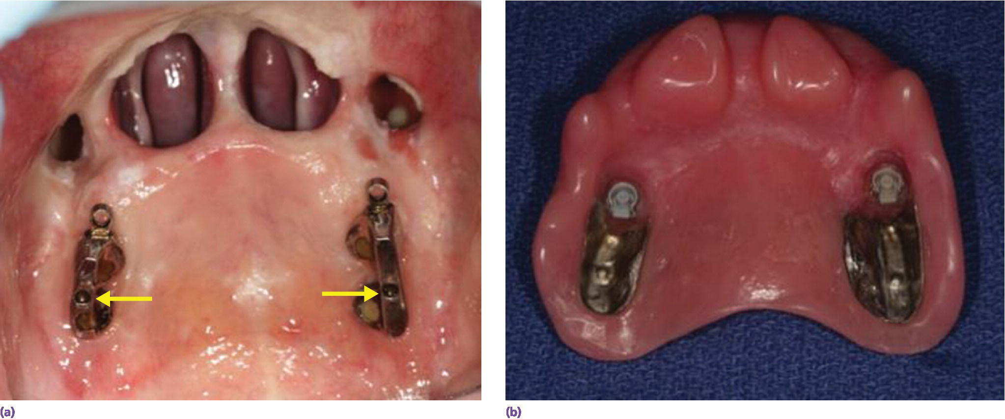
Figure 21.8 (a) Implants have been placed into the posterior alveolar ridge. The posterior implants on each side engage the pterygoid plates. Note the presence of rests and the resilient attachments. (b) The definitive prosthesis.
Lessons learned when using implants to retain large maxillary obturator prostheses
Implant connecting bar designs should be implant assisted as opposed to implant supported. The lever arms of large maxillary obturator prostheses can be excessively long and, as such, predispose to load magnification, triggering a resorptive remodeling response of the bone anchoring the implants. Given these conditions, the design of the implant connecting bar must accommodate multiple axes of rotation and direct occlusal loads along the long axis of the implants. Just as important, the ablative surgeon must create retentive, skin‐lined defects for the obturator prosthesis to engage, so as to counteract the forces of gravity and provide retention and stability for the prosthesis on the defect side.
Implant‐retained obturator prostheses for soft palate defects
Resection of tumors of the soft palate produces velopharyngeal insufficiency. Speech is hypernasal and the patient is unable to swallow food and liquids without nasal regurgitation. Obturator prostheses can be used to effectively obturate these defects and restore speech and swallowing. However, to do so effectively they must be securely retained and the obturator extension must be accurately positioned in the nasopharynx, so that it can properly interact with the residual velopharyngeal musculature. Retention is compromised when the residual hard palate is edentulous, because the surgical resection may compromise or extend into the posterior palatal seal area, making it difficult to obtain and/or maintain a peripheral seal.
In edentulous patients with soft palate defects, osseointegrated implants enable the design and fabrication of overdentures with retentive capacity similar to prostheses made for dentulous patients with residual dentition and a removable partial denture framework. If the soft palate defect has not resulted in compromise of the posterior palatal seal area and the residual palatal structures are favorable, two implants, placed into the premaxillary segment in the region of the canines, will be sufficient to supplement the retention, stability, and support derived from engaging the residual palatal structures. However, if the defect has compromised the posterior palatal seal area, and/or the residual palatal structures provide insufficient stability and support for the prosthesis, four or more implants should be placed. The retention provided by the implants will be enhanced if the implants are positioned to maximize AP spread. The design of the implant connecting bar and the retentive apparatus in these patients will depend upon a number of factors, such as the opposing dentition, the number and length of the implants, and the quality of the bone into which the implants were inserted, the AP spread of the implants, interocclusal space, and the size of the defect. In most patients the number and distribution of implants will require that occlusal forces be shared between the implants anteriorly and the traditional denture‐bearing surfaces posteriorly, and requiring an implant‐assisted design. Such a design in shown in Figure 21.9.

Figure 21.9 A typical defect restored with implants. (a) Implant connecting bar. Note the rests atop the bar between the implants. Note also that the defect extended to the posterior pharyngeal wall. Engagement of the velopharyngeal musculature will restore speech to normal. (b) Definitive prosthesis. (c) Prosthesis in position.
Source: Beumer et al., 2015.23 Reproduced with permission from Quintessence Publishing Company Inc.
These implant connecting bars can be designed and fabricated by either conventional means or with CAD/CAM techniques (Figure 21.10). When the implant connecting bar is designed and fabricated with CAD/CAM techniques, and is designed to be implant assisted, soft metals such as titanium should not be used. The constant movement and rotation of such a prosthesis will rapidly wear a bar made of titanium.
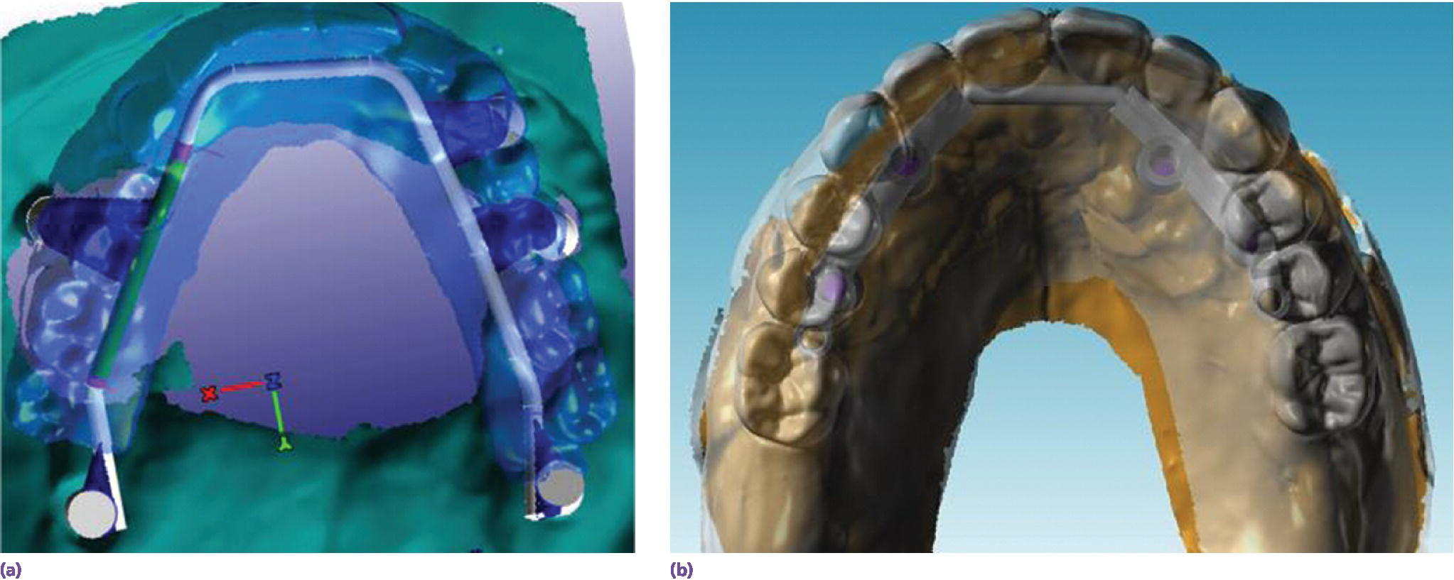
Figure 21.10 These implant connecting bars were designed and fabricated with CAD/CAM programs. (a) This bar is designed to be implant supported and so was milled from titanium. (b) This bar was designed to be implant assisted and was milled from chromium–cobalt alloy.
Congenital defects of the maxilla
Implants are particularly valuable when restoring dental and palatal defects in patients with congenital anomalies, especially patients with incomplete repair of hard and soft palate defects associated with cleft lip and palate. Frequently, these patients present with multiple missing or malposed teeth, collapsed arch form, oral antral fistulae, and class III jaw relations. A typical patient presenting with a partially repaired cleft palate is presented in Figure 21.11. Surveyed crowns were fabricated for the remaining maxillary molars and implants were placed anterior to these teeth in sites with suitable bone volume. Individual attachments were planned for use, so it was important that the implants be parallel to one another and their position compatible with the path of insertion of the proposed removable partial denture. They were positioned to provide anterior support for the removable overlay partial denture. To ensure parallelism, a surgical template was fashioned that permitted semi‐guided implant placement, i.e. the surgical template controlled the angulation and position of the osteotomy sites but not the depth. As is the case for most individuals with partially closed clefts denied modern methods of care, the plane of occlusion and tooth positions of the teeth associated with the opposing mandibular dentition were unfavorable. These discrepancies were resolved with conventional full‐veneer crowns.
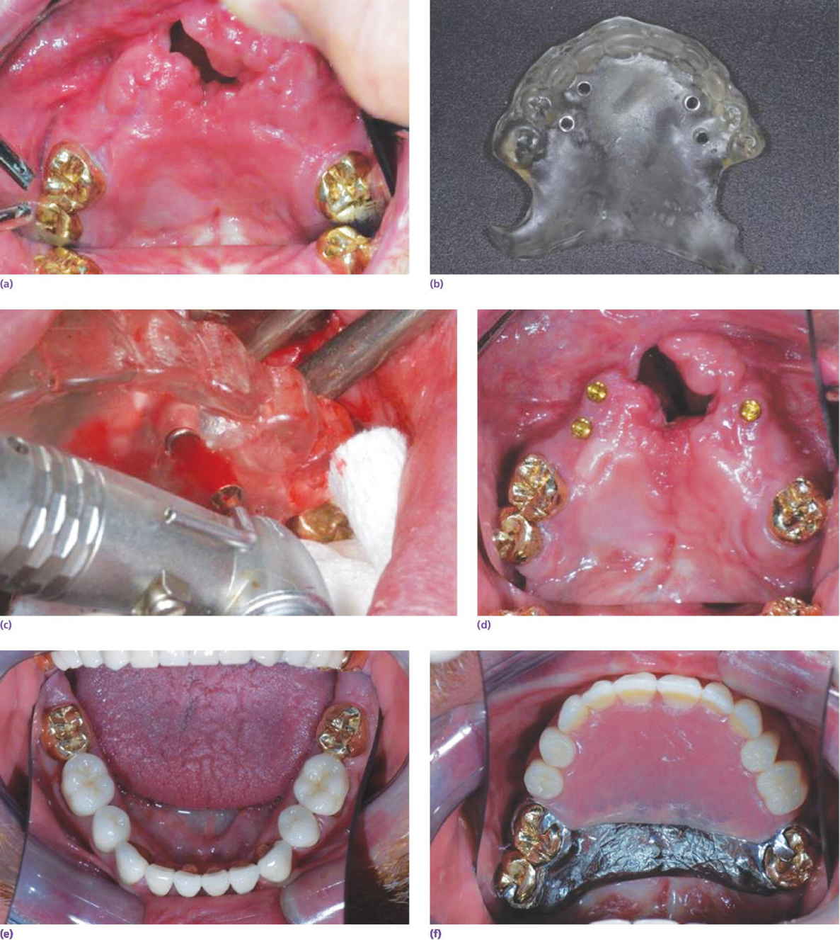
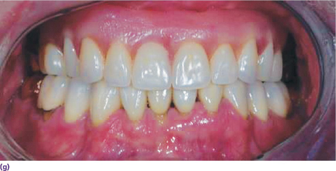
Figure 21.11 Patient with a partially repaired cleft to be restored with the aid of implants. (a) Surveyed crowns have been fabricated for the remaining maxillary dentition. (b) Surgical template. Note the presence of metal drill sleeves (bushings). These will ensure accurate positioning and angulation of each of the implants. (c) The implant sites are being prepared. (d) The implants in position with the attachments secured. (e) The restored mandibular dentition. (f, g) Completed overlay removable partial denture in position.
Source: courtesy of Dr Faulkner, Cincinnati, OH.
Combined surgical and prosthetic rehabilitation with CAD/CAM techniques
Obturator prostheses provide excellent rehabilitation for almost all patients with maxillary or combined maxillary–soft palate defects. However, some patients will encounter lasting problems with the retention of the prosthesis or favor a surgical closure of the defect for psychological or psychosocial reasons. A computer‐planned and ‐guided surgical reconstruction of missing soft and bony tissues, in combination with prosthetic restoration of missing teeth, may be desirable, especially in younger patients. With the advent of CAD/CAM technologies, new surgical and prosthodontic techniques are evolving, which, when properly executed in a multidisciplinary environment, provide patients with implant‐supported prostheses that very effectively and predictably restore form and function for these patients.1,24–27 However, surgical reconstruction of large maxillary defects should not be undertaken without the aid of CAD/CAM techniques. If surgical reconstructions are not properly planned and executed, irresolvable prosthodontic difficulties may be encountered due to poorly contoured, bulky tissues, lack of suitable bone volume for placement of implants, or poor positioning and alignment of implants.
In general this technique is best suited for secondary reconstruction after the patient is proven to be free of neoplastic disease. However, in selected patients, for example, those with well‐defined benign tumors, a primary preplanned reconstruction can be combined with a preplanned guided tumor ablation. When a vascularized free flap is used, the condition of both the donor site and recipient site vessels needs to be carefully assessed. Vascular disease with partial occlusion of blood vessels in the donor site is considered a contraindication, as it might lead to severe vascular problems in the donor region. The status of these vessels should be verified by digital subtraction angiography. In patients who had a previous neck dissection as part of their oncologic treatment, potential recipient blood vessels must be identified and properly assessed.
The defect should be of sufficient size, because the vascularization of small free flaps with bone grafts smaller than 2 cm is not predictable. In small defects, the use of free bone grafts can be considered, particularly if sufficient, well‐vascularized soft tissue is remaining or is introduced. In large defects, there is need for reasonable amounts of remaining bone at the recipient site to provide an appropriate means of fixation for the graft.
Scans are obtained from the donor site (most often the fibula) and the recipient site. The surgical reconstruction is planned based on the three‐dimensional (3‐D) models fabricated from these scans. Surgical guides designed to develop the osteotomy sites and the implant sites are fabricated. The implants are placed into the fibula and are allowed to osseointegrate. After a suitable period, the fibula is retrieved and osteotomized with the benefit of the surgical guide, and a prefabricated implant connecting bar or provisional prosthesis is secured to the bone flap to facilitate healing and consolidation of the graft. The graft is then secured to the recipient bone sites with mini‐plates and the vascular anastomoses completed. After a suitable period of healing and soft tissue consolidation, the definitive prosthesis is fabricated.
A detailed description of the CAD/CAM methods used for work‐up, the surgical templates used during surgical reconstruction and implant placement, and the fabrication of the provisional and definitive prostheses can be found elsewhere.1
Restoration of tongue–mandible defects with osseointegrated implants
The management of malignant tumors associated with the tongue, floor of the mouth, mandible, and adjacent structures represents a difficult challenge for the surgeon, radiation oncologist, and prosthodontist, relative to both control of the primary disease and rehabilitation following treatment. The most common intraoral sites for squamous cell carcinoma are the lateral margin of the tongue and the floor of the mouth. Both locations predispose the mandible to tumor invasion, often necessitating its resection in conjunction with resection of large portions of the tongue, the floor of the mouth, and the regional lymphatics.
Disabilities that may result from such resections are mostly due to impaired tongue function, and include impaired speech articulation, difficulty in swallowing, problems with mastication, altered mandibular movements, compromised control of salivary secretions, and cosmetic disfigurement. In the past 20 years, free tissue transfers (free flaps) and dental implants have resulted in considerable improvement in the form and function of these patients. Using these new surgical and prosthodontic methods, more patients with tongue–mandible defects can be restored in appearance and function to levels that approach their presurgical condition. However, these rehabilitative efforts are complex and require the efforts of a sophisticated, well‐trained, multidisciplinary team of oncologic surgeons, maxillofacial prosthodontists, reconstructive surgeons, speech therapists, clinical psychologists, and others.
Anterior defects with mandibular continuity retained or restored
Stay updated, free dental videos. Join our Telegram channel

VIDEdental - Online dental courses


