21
3D Diagnosis and Management of Facial Asymmetries
Introduction
Craniofacial deformities occur in around 5% of the U.S. population. Of these individuals, 2% have facial asymmetry severe enough to be disabling and stigmatizing. Facial asymmetry includes a spectrum of malformations that result from maxillary and/or mandibular hypoplasia or hyperplasia on the affected side of the face (Severt & Proffit, 1997; Proffit et al., 1998). Because of challenges in identifying the precise location and magnitude of the asymmetric structures in the face, this entity often poses a challenge in diagnosis and treatment planning. Also due to the wide variability in the etiology and presentation of the disorders, the proper assessment and quantification of the differences between the right and left sides is crucial for optimized diagnosis, treatment planning, and follow-up of these patients.
Although cephalometric radiography has been and probably will continue to be the routine radiographic examination for many patients seeking orthodontic treatment with or without orthognathic surgery, the “inappropriateness of conventional cephalometrics” for these purposes had been recognized as early as 1979 (Moyers & Bookstein, 1979). These two-dimensional (2D) radiographs are problematic particularly when rotational or asymmetrical correction is required, since the clinical presentation of these disorders and their surgical correction are inherently three-dimensional (3D; Sandor et al., 2007).
The use of cone beam computed tomography (CBCT) or spiral computer tomography (CT) provides the 3D imaging data necessary to generate precise knowledge of the location and the magnitude of specific features contributing to the asymmetry, which are essential for the diagnosis of facial deformities and planning of corrective procedures. Even though the clinician may be able to visualize facial asymmetry in 3D surface models, this does not imply necessarily that he or she has the capability to quantify and precisely locate sites of the asymmetry. For optimized diagnosis and treatment planning of asymmetric patients, the clinician must have the ability to perform a detailed analysis of the positional and morphological discrepancies between the normal and affected sides of the face. An increasing number of studies have demonstrated that computer-aided surgical simulation (CASS) can predict possible surgical complications and lower material costs while decreasing the duration of surgery, with comparable or better surgical outcomes (Xia et al., 2000a, 2000b; Hassfeld & Muhling, 2001; Troulis et al., 2002; Gateno et al., 2003, 2007). These approaches could prove highly valuable in the diagnosis and treatment of facial asymmetries.
3D imaging and associated image analysis methods developed recently have the potential for additional advancements that will contribute to enhancing and quantifying the diagnosis of facial asymmetries. The use of relatively low radiation dose CBCT scanners in dental practices facilitates the examination of anatomical structures in a multiplanar view. It also provides a rich data source for the application of different image analysis techniques to further extract diagnostic information from available volumes. Creation of 3D virtual surface models from CBCT volumes, registration of these models, and measurements of the surface distances between different models is a well-documented approach used to study growth, treatment changes, and the stability of those changes (Chapter 19; Cevidanes et al., 2005a, 2005b, 2005c, 2006, 2007). This chapter provides the necessary and essential background in novel methods for 3D assessment and management of mandibular asymmetry that take advantage of the promising advancements in 3D hardware and software technologies. These approaches described for mandibular asymmetries have applications to asymmetries affecting other parts of the face.
Midline Determination and Mirroring Techniques
Various approaches have been described in the literature in an attempt to use 3D imaging for the detection and quantification of craniofacial asymmetry (Katsumata et al., 2005; Maeda et al., 2006; Park et al., 2006). Most of these techniques depend on landmark identification and manual identification of a straight “midsagittal plane,” both of which are challenging and prone to operator error.
Prima and colleagues (2002) presented a method to define the midsagittal plane of the brain automatically in 2D cross-sectional slices; however, the accurate definition of the mid-sagittal plane in the maxillofacial area as proposed in this study remains a challenge because the plane is a curved surface in faces that have a chin deviation. In 2005, an alternative method for determining a plane of symmetry that mirrors the mandible in any arbitrary plane with rigid registration of the mirrored mandible to the original image was proposed (Glerup, 2005). However, this procedure did not take into consideration the morphological relationships of the mandible to the maxilla and the cranial base. A modification of this approach that first mirrors the entire image including the mandible and then registers it on the cranial base can provide information on the entire facial structure rather than just the mandible (Cevidanes et al., 2006).
AlHadidi and colleagues (2011) compared these two previously proposed methods of assessing mandibular asymmetry (Glerup, 2005; Cevidanes et al., 2006). The first method uses mirroring of the mandible in the mid-sagittal plane (Figure 21.1); the second uses mirroring of the mandible and registration on the cranial base (Figure 21.2). For the first approach, a mid-sagittal plane was defined for each of 22 randomly selected asymmetric patients as the plane passing through nasion (Na), anterior nasal spine (ANS), and basion (Ba). This mid-sagittal plane and the degree of asymmetry were determined five times from this patient cohort. Differences between repeated assessments of asymmetry served as a measure of reproducibility of mid-sagittal plane identification. Additionally, mirror images for both halves of the mandible were created.
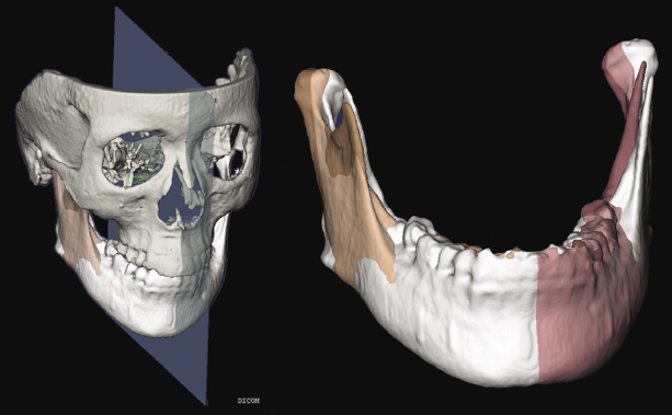
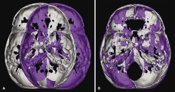
The second approach consisted of mirroring the image volume by flipping the left and right sides and then registering the mirrored image onto the cranial base using a mutual information maximization method. Both mirroring techniques provided similar quantification of mandibular asymmetry in the patient cohort studied; however, neither approach could be applied indiscriminately to any patient. The findings showed that mirroring using the mid-sagittal plane generates inaccurate and clinically irrelevant results for patients such as those with cleft palate who present with facial features that affect the midline position of the points (NA, ANS, Ba) used to define this plane. Similarly, in patients with asymmetries involving the cranial base, registration on the cranial base also results in suboptimal results. This implies that patient-specific methods may be indicated for optimal localization and quantification of mandibular asymmetries.
Segmentation and Surface Distance Computation
Using 3D imaging analysis, mandibular asymmetry has been quantified as the surface distances between the affected side of the mandible and the mirror image of the opposite side. Surface models of mandibles need to be segmented out of the original volumes for surface distance measurements.
Segmentation involves outlining the shape of structures visible in the cross-sections of a volumetric dataset in the CBCT-3D images. Segmentation of anatomic structures can be performed using ITK-SNAP, which is an open-source software (http://www.itksnap.org; Yushkevich et al., 2006). 3D virtual models then are built for each patient from a set of approximately 300 axial cross-sectional slices for each image with the image voxels reformatted for an isotropic resolution of 0.5 mm × 0.5 mm × 0.5 mm. This resolution is used because higher spatial resolution wi/>
Stay updated, free dental videos. Join our Telegram channel
VIDEdental - Online dental courses


