20
Applications of Cone Beam Computed Tomography to Orthognathic Surgery Treatment Planning
Introduction
Cone-beam computed tomography (CBCT) has created the potential for several advancements in orthognathic surgery. As opposed to two-dimensional (2D) radiography, three-dimensional (3D) CBCT imaging offers improved analysis of craniofacial deformities, improved quality control with enhanced post-operative assessment of surgical results, and the potential to improve and streamline the process by which orthognathic surgical planning is transferred to the operating room. The objective of this chapter is to present evolving concepts on the utilization and efficacy of CBCT in enhancing diagnosis and treatment outcomes in orthognathic surgery.
Advantages of In-Office CT Scanning
CBCT scanning generally is inferior to conventional multi-slice CT (MSCT) scanning in image quality. In spite of this, its popularity has grown exponentially in dental specialties because of the increase in diagnostic quality and three-dimensionality of the images compared with conventional dental radiographic imaging. CBCT also offers significant advantages in dosimetry and, since most CBCT units are located in dental offices, provides greater patient and provider convenience than medical imaging. The ability to locate CBCT units in dental offices is facilitated by virtue of their small footprint (which often is no greater than an orthopantomogram unit), lack of need for special electrical installations, and affordability. A second important advantage of in-office CBCT is that splints and other dentally relevant markers can be made in an onsite dental lab and used during the scan for registration and diagnosis. Furthermore, most CBCT scans taken in a dental office typically are performed by a dental assistant who is familiar with concepts of capturing the condyles and having the patient’s lips in resting posture with the mandible in centric relation. This contrasts with medical radiologists undertaking MSCT in hospitals who typically are not cognizant of or acquainted with these important concepts of dental imaging and therefore are likely to overlook them.
Evolution from 2D to 3D Radiography for Orthognathic Surgery
Cephalometric analysis is a hallmark in the proper diagnosis and treatment planning for patients with severe malocclusion. A myriad of analyses are available (Wylie et al., 1987), some preferred by orthodontists and others by surgeons. Most of the more popular cephalometric analyses for orthodontists utilize several angular measurements that are excellent for evaluating tooth position, but are less precise in assessing jaw position (Steiner, 1953; Ricketts, 1981). In addition, nearly all lateral cephalometric analyses use intracranial reference marks that are difficult to identify and, rather than using operator-assisted natural head position (NHP), use reference planes such as the Frankfort Horizontal Plane that are more appropriate for anthropology (Broca, 1862). Finally, angular measurements are difficult to translate to planning and implementing surgical changes. To overcome these deficiencies, a cephalometric analysis was developed (Burstone et al., 1978; Legan & Burstone, 1980) that uses mostly millimetric linear measurements made in the NHP that correspond to the various types of surgical movements the surgeon can accomplish during orthognathic surgery and are transferable directly to the operating room.
Even with the improved lateral cephalometric analysis, the third dimension in the transverse or coronal plane largely has been overlooked. Subsequently, two significant papers were published to highlight the importance of the transverse dimension in surgical orthodontic treatment planning (Grummons & Kappeyne van de Coppello, 1987; Betts et al., 1995). Unfortunately, the only tool available at the time for transverse analysis was the postero-anterior (PA) cephalogram, which is fraught with exposure and tracing errors. These errors result from small rotations in head position during exposure that lead to inaccurate diagnosis of asymmetry, and the substantial superimposition artifacts make the PA cephalogram difficult to read and interpret and consistently identify landmarks (Major et al., 1994, 1996).
The deficiencies of both the lateral and the PA cephalometric analyses can be overcome with CBCT. Not only do CBCT data enable the accurate creation of 2D radiographs (Bholsithi et al., 2009; van Vlijmen et al., 2010; Pape et al., 2012; Zamora et al., 2012), but by navigating slice by slice through the dataset to avoid superimposition artifacts, the scans also permit much more accurate measurement of the recommended PA cephalometric dimensions than do PA cephalograms. However, while utilizing traditional cephalometric analysis on 2D images derived from CBCT is a step in the right direction, this methodology does not harness the full power and capabilities of this imaging technology. Currently, attempts are being made to perform true 3D structure analysis with CBCT. The methods are in their infancy and many still need to be validated (Fuhrmann et al., 1996; Olszewski et al., 2006; Noguchi et al., 2007; Chenin, 2010), but a true 3D cephalometric analysis that complements the 3D clinical and facial exam and utilizes the same terminology that surgeons use will be a tremendous asset for more accurate diagnosis of and treatment planning for the surgical patient, particularly the asymmetric patient.
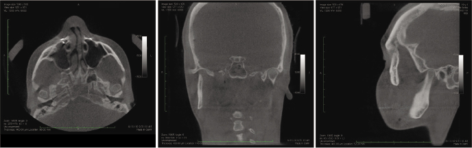
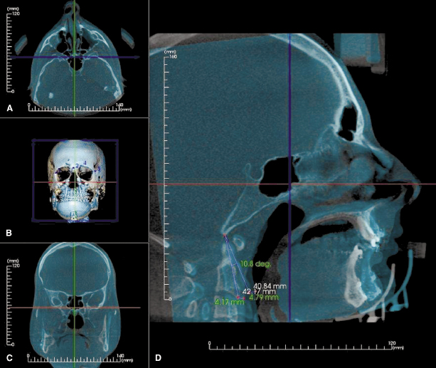
From the surgeon’s perspective, 3D imaging offers multiple advantages when preparing for and evaluating the results of an orthognathic surgery case. Pre-operative assessment of bone support of the dentition and interdental spacing for interdental osteotomies ideally is performed with CBCT imaging (Figure 20.1). For example, this 3D assessment helps to eliminate parallax errors, visualize variations in root anatomy such as dilacerations, and determine the pre-operative position and course of the inferior alveolar nerve, which can be useful for planning slight variations in the position of the sagittal split osteotomy to help minimize injury to the nerve.
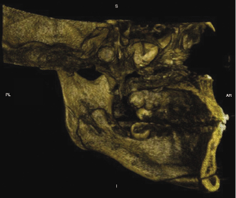
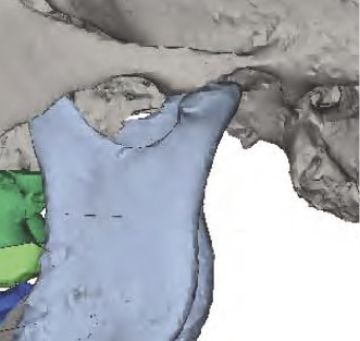
Post-operative assessment with 3D imaging allows a high-resolution determination of osteotomies and fixation that are essential in implementing continuous quality improvement processes. These include enabling surgeons to appraise their results critically, thereby helping to avoid making the same mistakes and facilitating evolution in their techniques. For example, CBCT enables (1) the documentation of the incidence and position of pterygoid plate fractures and of deflected septums after LeFort osteotomies; (2) good visualization of the position of the Hunsuck fracture in the bilateral sagittal split osteotomy (Figure 20.2); (3) visualization and documentation of pre-surgical centric relation (Figure 20.3) and post-operative alterations in condylar anatomy, condylar position, as well as errors in achieving centric relation (Figure 20.4); and (4) pre- and post-surgical superimpositions to be performed to document condylar changes and to elucidate the precision in achieving pre-operative plans (Figure 20.5).
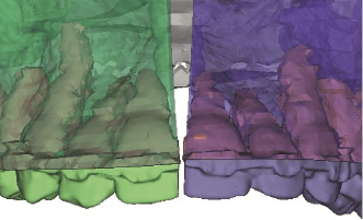
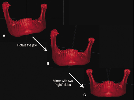
Another example where CBCT offers distinct advantages over 2D imaging is in the diagnosis, treatment planning, and correction of facial asymmetries in which the CBCT dataset can be segmented to better visualize, localize, assess, and quantify a patient’s asymmetry. Once segmented, the surgeon can use the mirroring technique to plan the surgical procedures virtually in substantial detail for subsequent delivery of treatment in the operating room (Peck & Peck, 1970; Figure 20.6; see also Chapter 21).
Computer-Assisted Orthognathic Surgery (CAOS)
Orthognathic surgery constitutes a powerful combination of orthodontic and surgical techniques that permit the 3D repositioning and reconstruction of the facial skeleton, offering significant functional, esthetic, and psychological benefits to patients with moderate to severe skeletal discrepancies. Over the past few decades, the process by which these cases are prepared, planned, and effected has evolved to be relatively precise but labor-intensive and time-consuming. Many of the steps involved in the delivery of care to these patients cannot be delegated and, as such, are surgeon-intensive. For example, most surgeons will take their own facebow and centric relation records, while impressions may be delegated to an assistant. Model surgery and splint fabrication also are performed by the surgeon. The asymmetric face, whose details and specifics cannot be captured completely or measured precisely both clinically and with conventional 2D cephalometrics, poses additional diagnostic problems. These hurdles, along with concerns about declining reimbursement rates for orthognathic surgery, have led to a decline in surgeons’ willingness to offer orthognathic surgery as a service to their patients. 3D imaging including CBCT offers substantial promise in overcoming many of these hurdles of traditional approaches and steps in undertaking orthognathic therapy. These include refined 3D diagnosis, virtual treatment planning, and computer-assisted algorithms for deriving optimal approaches to pre-planning and delivery of intraoperative procedures. The practicality of performing each of these steps has been advanced greatly with the advent of in-office CBCT technology. The integration of advanced imaging and planning software will continue to improve our understanding of a deformity, allow creation of better surgical plans, and improve the efficiency of the process of transferring this planning to the operating room. The entire process, often referred to as Computer-Assisted Orthognathic Surgery (CAOS), is readily adoptable by the oral and maxillofacial surgeon because its end product, the occlusal surgical splint, is identical to that produced in conventional planning methods, to which the surgeons already are well accustomed.
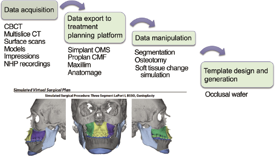
The general workflow of CAOS is shown in Figure 20.7. At its simplest, CT or CBCT images and dental models are merged to create a virtual model of a patient’s skull and occlusion. These data are manipulated virtually to simulate the desired surgical plan. Once these simulations are complete to the satisfaction of the surgeon, the data are exported to rapid prototyping hardware to generate templates that will guide the operation. If the process is accurate and the templates are effective, then the operation and its results will match the virtual plan. Thus, CAOS is dependent on specialized software that permits analysis, surgical simulation, and design and fabrication of surgical splints.
There has been recent commercial interest in developing software to facilitate orthognathic surgery diagnosis, treatment planning, and splint fabrication. The two most commonly used software platforms are Simplant OMS (Materialise NV, Leuven, Belgium) and Maxilim (Medicim, Mechelen, Belgium); the former is used most commonly in North America. Splints can be manufactured using a variety of rapid prototyping techniques, such as stereolithography (SLA) and selective laser sintering (SLS).
Simulating orthognatic surgery in the virtual environment requires the same exigencies as conventional cephalometrics and model surgery. When understanding this new process, it is helpful first to compare it with the more familiar traditional paradigm. With the computer-assisted plan, the CT or CBCT images serve as the semi-adjustable articulator with mounted models. For this to be precise, the scan must be acquired in centric relation and a clear view of the occlusion obtained. Orthodontic appliances pose a substantial problem in this regard because of the considerable artifact created around the dentition during CBCT/CT scanning. This precludes a CBCT/CT scan from being a reliable source of optimal occlusal detail. Large dental restorations would have a similar impact on the optimal representation of occlusal and dental anatomy. The CBCT/CT imaging artifact is circumvented best by using scanned dental models that can be surface-imaged using a laser or CBCT or CT sca/>
Stay updated, free dental videos. Join our Telegram channel
VIDEdental - Online dental courses


