Chapter 2 Dental Materials
Section A Evolution, Description, and Application of Dental Materials
Historical Perspective
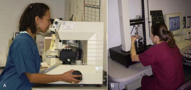
The birthplace of many dental materials is the Paffenbarger Research Center (PRC) (Figure 2-1, A), the American Dental Association’s (ADA’s) Research Unit in Gaithersburg, Maryland. PRC was established in 1928 to collaborate with the National Bureau of Standards (now called the National Institute of Standards and Technology [NIST]) to develop science-based specifications for dental products. Familiarity with these institutions and pioneers gives a good historical perspective on materials development and the improvements made over the years. It also yields a good perspective on how the standards process of the ADA began and its vital role in defining what dental materials are and how they are used.
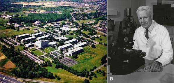
FIGURE 2-1 A, American Dental Association Foundation’s Paffenbarger Research Center. B, Dr George Paffenbarger.
Silicate Replacements
Dr George Paffenbarger (Figure 2-1, B) joined the scientists at the Research Unit in 1929 and quickly became the unit’s lead scientist. In 1985 the ADA renamed the Research Unit in Dr Paffenbarger’s honor. Dr Paffenbarger did considerable research in silicates and was strongly interested specifically in silicate cements. In the 1950s and early 1960s, silicates were the only good anterior restorative materials available. Dr Rafael Bowen (Figure 2-2) (the primary developer of dental composites) was a dentist in private practice in Southern California who had a hobby interest in chemistry. A major frustration he faced in his practice was that every time he placed silicate cement he had to explain to the patient that it would last for only a short time and would eventually have to be replaced. Bowen’s passion was to find a better material to replace the silicate cements. In his “back porch chemistry lab” he explored new technologies, such as other types of composites and other polymers such as epoxies. He made the first composites using porcelain by grinding up denture teeth with a mortar and pestle and mixing them into epoxy resins, forming the early prototype of dental composites. He tried these on a patient or two but quickly realized that the epoxy resin was not a good matrix material because the setting was slow, it was very difficult to work with, and the toxicity of some of its components was a concern. He then began synthesizing other types of restorative resins to use in place of epoxy. The first one he developed was bisphenol A glycidyl methacrylate (BIS-GMA). Paffenbarger took notice of this development through Bowen’s presentations and publication of his work and invited him to PRC.

Basic Material Descriptions
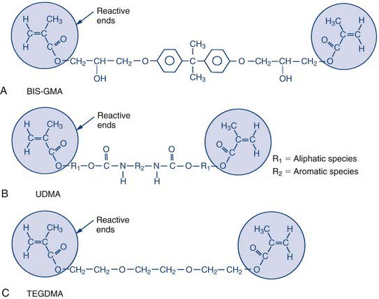
The backbone of a dental composite is basically a liquid acrylic resin made up of bifunctional molecules. These bifunctional molecules have a methacrylate functional group on each end, and these are the groups that tie or link together during the curing process. During the curing process they link to form long molecular chains, which is what causes the material to thicken and eventually harden. They can also form cross-links between chains; the units on the ends of the molecules attach from one chain to another or attach to smaller resin molecules that bridge between the chains. This cross-linking process ties the chains together and stiffens the material, making it more rigid (Figure 2-4).
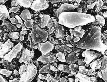
The filler component (Figures 2-5 and 2-6) is largely made up of finely ground glasses, either ground from solid glass frit or manufactured through the sol-gel process, a chemical process that involves the precipitation of small particles out of liquid solutions. The composite includes particles in various size distributions so the smaller ones can fill the spaces between the larger ones, yielding a higher density of packing within a given volume.
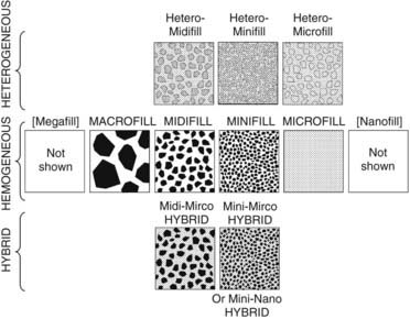
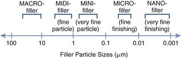
FIGURE 2-6 Composite filler ranges versus particle size (shown on a logarithmic scale).
(From Roberson TM, Heymann HO, Swift EJ: Sturdevant’s art and science of operative dentistry, ed 5, St Louis, 2006, Mosby. Courtesy S.C. Bayne, School of Dentistry, University of North Carolina, Chapel Hill, North Carolina.)
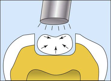
Initiators known as photoactivators, the most common of which is camphorquinone, work in much the same way (Figure 2-7). The camphorquinone will form a radical when excited by a particular wavelength of light. The most common wavelength used today is the blue light with a wavelength of approximately 470 nm. This is what is used to start off the chain reaction of polymerization. The two other, less commonly used initiator wavelengths are 429 and 390 nm and are used to excite different photoinitiator molecules.

Physical Properties of Importance
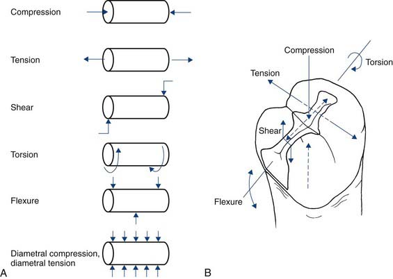
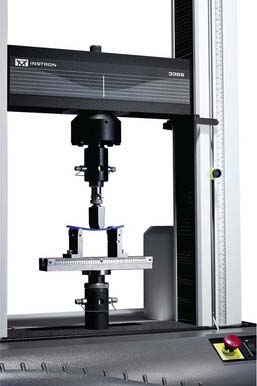
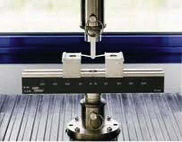
A number of physical properties are commonly measured in composites, some via the ISO Standards testing (Figures 2-8 and 2-9). Some of these properties have direct clinical relevance. The first one is strength. The most common strength measured is flexural strength (Figure 2-10), referring to how much the material will bend or flex before it breaks. It is probably the most relevant property clinically because, when considering how fillings support the forces of mastication, marginal ridges and occlusal tables must be able to support contact stresses. Flexural strength reflects the tensile strength of the material, and this refers to how much one can pull or bend a material before it will break. Most composites have flexural strengths in the 100- to 150-megapascal range. This appears to be the strength required for success from a clinical standpoint for composite restorations.
Another important property for polymers and other composites is how stiff they are—the elastic modulus (Figure 2-11). Stiffness measures indicate how much load a material will support before it starts to deform or how much it will resist deformation and bending. Restorations under loading should not flex significantly. All materials deform under load, but this deformation should not be great enough to break bonds and marginal seals. Ideally the restoration should be stiff enough to resist breaking the bond or the seal around the edges, a property that is also clinically relevant.
The third property measured in composites is toughness (Figure 2-12), which is really a measure of how well the material resists crack growth. All dental restorations sustain damage over time. They undergo loading with chewing, they fatigue, they form cracks, and they form surface defects. Toughness is the ability to resist the growth of those cracks or defects. Filling materials should have a fairly high degree of toughness. Most composites perform fairly well in this area, and all are much tougher than ceramics. If a ceramic has a small crack or defect, its lack of fracture toughness will allow that crack to grow quite easily, whereas a composite will better resist crack growth.
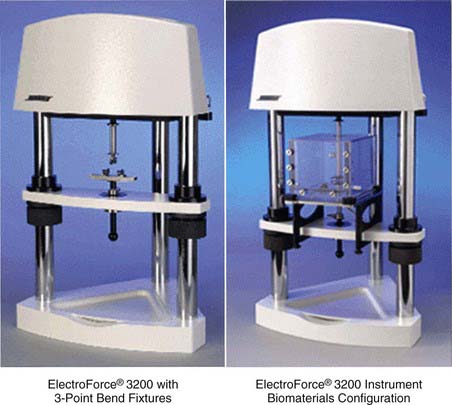
FIGURE 2-12 Measuring toughness using ElectroForce® 3200 test instruments.
(Courtesy Bose Corporation, ElectroForce Systems Group, Eden Prairie, Minnesota.)
Another relevant property is expansion (Figure 2-13). This includes both thermal expansion and hydrolytic expansion. The thermal expansion values of composites are usually about three times those of tooth structure. With hot and cold, composites expand and contract more than the surrounding tooth structure, putting stress on the adhesive interface. This does not affect the composite material per se, but it does alter the bonded interfaces and result in breakdown of adhesion.
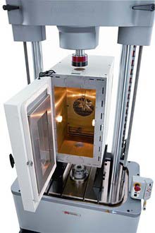
FIGURE 2-13 Thermohydraulic expansion measurement performed on an ElectroPuls™ E10000 linear motor test instrument.
(Courtesy Instron®, Norwood, Massachusetts.)
Another important composite property is polymerization shrinkage (Figure 2-14). One of the inherent properties of a composite that uses methacrylate-based resins that undergo chain polymerization is that they transform from what are called van der Waals spacing to covalent bonds between the molecules. During this polymerization process the molecules actually move closer together, so the material physically shrinks. Composites each have a characteristic curing shrinkage, but shrinkage of the pure matrix resin is 8% to 10%. Typically, by the time all the filler is packed in, much of that resin has been displaced, which brings the shrinkage down to about 2% to 2.5%. As the material shrinks, it puts stress on bonds or can open up margins. Over the years much effort has been expended trying to develop materials with lower and lower shrinkage. When more of the resin is displaced, less shrinkage can result. More filler and less resin results in a lower-shrinking material. Shrinkage and the stress produced during shrinkage are also affected by the volume of material, the shape of the cavity preparation, how fast the materials cure, and how much they cure. Considerable effort has also gone into reducing shrinkage stress by controlling the curing rate of composites. Many factors enter into the curing process, but the lowest shrinking materials are generally in the 1% shrinkage range. No resin matrix composite has yet been able to totally eliminate polymerization shrinkage.
Classes of Composite Materials
The classes of composites are generally based on the size of the filler particles. The earliest class of composites is referred to as macrofilled materials (Figure 2-15). These are not used much anymore and consist generally of composites made with large filler particles. Most of the early chemically cured macrofills used ground glass filler particles measuring up to 10 µm or more in average diameter.
Today hybrid or smaller-particle materials are most common (Figure 2-16). A hybrid contains different-sized filler particles ranging from very small submicron size to 2 or 3 µm in average diameter. This broad range of sizes allows hybrids to achieve extremely dense particle packing. Hybrids tend to be the most highly filled systems available today.

Microfill materials also have a mixture of particle sizes, but across a narrower range of diameters (Figure 2-17). The particles are 0.5 µm or less and can achieve a relatively high packing density. Because the particles are very small, it is also possible to finish and polish them very smoothly. They exhibit good optical characteristics, transmitting light quite well, and a/>
Stay updated, free dental videos. Join our Telegram channel
VIDEdental - Online dental courses


