Wrought Metals
 Critical Question
Deformation of Metals
In Chapter 4, the principles of elastic and plastic deformation are described relative to their effect on mechanical properties. For example, when the stress induced by an applied tensile force is below the proportional limit, the separation between metal atoms is increased a very small amount from the equilibrium interatomic spacing in the crystal structure (Chapter 2). Plastic deformation occurs when the applied stress increases above the elastic limit. We often use the proportional limit as the property of interest here, since it can be determined easily from stress-strain plots and its value is slightly lower than its elastic limit (Chapter 4). Yield strength, which is slightly greater than the elastic limit, is used when the proportional limit is not well defined. When this force is reduced, the interatomic separation returns toward its equilibrium value. However, once the proportional limit of a metal is exceeded at a sufficiently high applied force, permanent (plastic) deformation of the metal occurs. Some alloys, such as dental amalgams, will undergo brittle fracture rather than a significant amount of permanent deformation, as noted in Chapters 4 and 15. Only the elastic strain is recovered after loading is released from a metal that has been loaded beyond its proportional limit.
Theoretical and Observed Shear Strengths of Metals
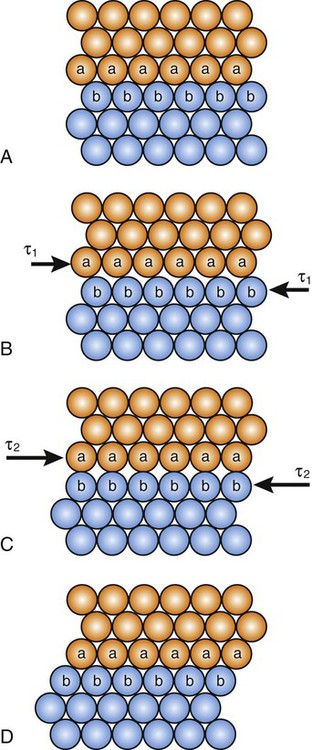
An atomic model illustrating permanent deformation of a metal of perfect crystalline structure subjected to an applied shear stress is illustrated in Figure 17-1. Notice that the deformation or slip process requires the simultaneous displacement of plane A atoms relative to the plane B atoms. If the elastic modulus in shear is known for a given metal, this model can be used to calculate the maximum theoretical shear strength. However, studies have shown that theoretical shear strengths are much higher than those observed from mechanical testing of polycrystalline metals. For example, the differences for copper and iron are approximately 40 times greater and can be as much as 190 times greater for SiC (Table 17-1). The table also shows that only whisker specimens, which are very thin single crystals of pure materials that have near perfection in their atomic lattice, exhibit shear strengths approaching their theoretical values. The key difference between whiskers and bulk polycrystalline specimens of the same material is the presence of crystal imperfections at the atomic level in the bulk material.
TABLE 17-1
Theoretical and Observed Shear Strength
| Materials | Shear Modulus (GPa) | Observed Ultimate Shear Strength* (MPa) | Calculated Ultimate Shear Strength (GPa) | Observed Ultimate Shear Strength† (GPa) |
| Copper | 48 | 220 | 7.7 | 2.1 |
| Iron | 80 | 290 | 12.4 | 9.5 |
| Nickel | 76 | 480 | — | 2.7 |
| Al2O3 | 170 | — | 12.1 | 14.6 |
| BeO | 140 | 280 (tension) | 21.7 | 9.2 |
| SiC | 200 | 170 (tension) | 32.3 | 14.6 |
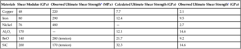
†Whisker; the shape of the whiskers is not conducive to shear testing.
From Eisenstadt M: Introduction to Mechanical Properties of Materials. Upper Saddle River, NJ, Prentice-Hall, Inc, 1971.
 Critical Question
Crystal Imperfections
Crystallization (Chapter 5) from starting nuclei during solidification of a metal does not occur in a regular fashion of atomic plane by atomic plane; instead, growth is likely to be random and imperfect. When lattice positions have missing atoms, displaced atoms or extra atoms, they are called point defects. The edge of an extra plane of atoms in the crystal is called a line defect. The boundaries between crystals or the external surface of the crystal are also considered imperfections in the crystal.
Point Defects
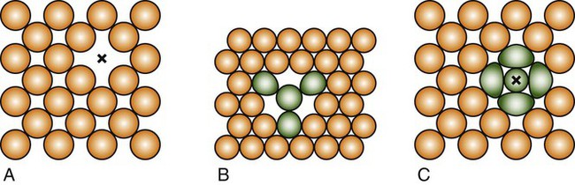
A vacancy or vacant atom site in a crystalline lattice may occur at a single site in the atomic arrangement (Figure 17-2, A), and two vacancies may condense as a divacancy (Figure 17-2, B); a trivacancy may also exist. An interstitial atom is illustrated in Figure 17-2,C. Vacancies and other point defects are equilibrium defects, and a crystalline material that is in equilibrium will contain a certain number of these defects at a given temperature. The most important point defects are vacancies, which provide the principal mechanism for atomic diffusion in crystalline materials.
Line Defect (Dislocations)
The simplest type of line defect, known as an edge dislocation, is illustrated in Figure 17-3, A, for a simple cubic structure. It can be noted that the atomic arrangement is regular except for the single vertical plane of atoms that is discontinuous. The edge dislocation (symbolized by ⊥) is located at the edge of the half plane.
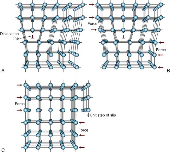
If a sufficiently large shear stress is applied across the top and bottom faces of the metal crystal in Figure 17-3, A, the bonds in the row of atoms adjacent to the dislocation will be broken and new bonds with the next row will be established, resulting in movement of the dislocation by one interatomic distance, as indicated in Figure 17-3, B. Continued application of this shear stress causes similar movements of one interatomic distance until the dislocation reaches the boundary of the crystal. The plane along which an edge dislocation moves is known as a slip plane. It can be seen in Figure 17-3, C, that the result of this dislocation movement across the crystal is that the atomic planes on one side of the slip plane have been displaced one interatomic spacing (one unit of slip) with respect to the atomic planes on the other side of the slip plane. The crystallographic direction in which the atomic planes have been displaced is termed the slip direction, and the combination of a slip plane and a slip direction is termed a slip system.
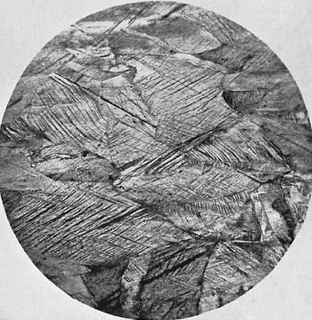
It is evident that much less shear stress is required to cause permanent deformation of the metal crystals that contain edge dislocations (Figure 17-3), since only one row of atomic bonds is broken at a time, compared with the perfect crystal, where all rows of atomic bonds across the two planes (Figure 17-1) must be simultaneously broken for shear deformation to occur. This accounts for the difference in Table 17-1 between the values of theoretical shear strength for a dislocation-free metal whisker and a polycrystalline metal containing dislocations. The proportional limit for a metal generally corresponds to the onset of significant movement of dislocations. The slip lines in Figure 17-4 correspond to slip planes where large numbers of dislocations exit the metal, causing surface offsets that scatter the light used for observation. Thus, one can conclude that plastic deformation of metal is the result of dislocation movement and slip between atomic planes.
 Critical Question
Dislocation Movement IN Polycrystalline Alloys
Figures 17-3 and 17-5, A, illustrate one dislocation moving in a pure metal crystal; it appears that there is little hindrance of a moving dislocation along its slip plane. In reality there are several scenarios in which dislocation movement can be impeded in pure metals and alloys. Alloys contain multiple phases, such as solid solutions and/or precipitates (Chapter 5), in addition to the numerous dislocations and grain boundaries found in pure metals. These crystal structural features represent obstacles that may be overcome by an application of increased stress to promote dislocation movement.
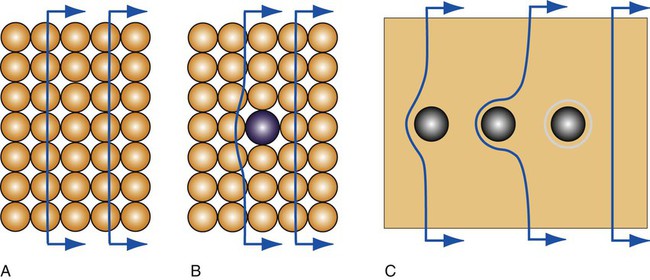
For solid solution alloys, the atomic arrangement near solute atoms is locally distorted. The movement of dislocations along the slip plane will be impeded by the presence of such solute atoms (Figure 17-5, B). Precipitates can be coherent, where the atomic bonds are continuous across the interface with the solid solution matrix, or incoherent, where interatomic bonds are not continuous across the interface. Coherent precipitates generate localized distortion in the atomic arrangement and have the same crystal structure as the matrix phase. Dislocations cannot move through incoherent precipitates but instead form loops of increasing size around these particles (Figure 17-5, C). Additional stress is needed to move dislocations through distorted regions, including coherent precipitates, or around incoherent precipitates.
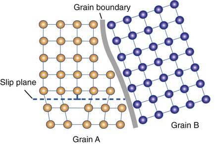
It is difficult for a dislocation to pass into another grain, especially if the adjacent grain is misaligned (Figure 17-6). Grain boundaries represent the end of slip planes where dislocations cease to move and accumulate. As the grain size decreases, there will be more grain boundary area per unit volume to impede dislocation motion. Grain size can be controlled by rapid cooling or quenching (Chapter 5) or by inclusion of a grain refiner (Chapter 16), such as beryllium in Ni-Cr-Be alloys. Cold working also alters the shapes of grains significantly (i.e., the grains may be severely elongated parallel to the wire axis).
 Critical Question
Effects of Strengthening Metals
Based on the principle that impeding the movement of dislocations strengthens cold-worked metals, it follows that the hardness, yield strength, and proportional limit are increased with each of the strengthening mechanisms just described, whereas the ductility is decreased. The corrosion resistance is also decreased for a permanently deformed metal, since the dislocations produce localized regions of strain at the atomic level, which have higher energy than atomic arrangements in the undeformed metal. Corrosion is a process of relieving stored energy (Chapter 3), and it can be minimized by stress relief (discussed later).
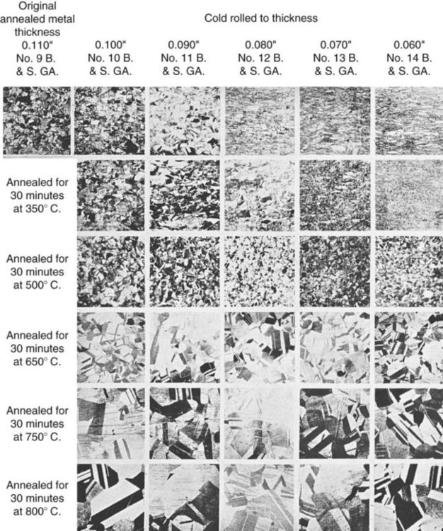
One can visualize the effects of severe cold working on the grain structure of a copper-zinc alloy (brass). This is shown in the first row of photomicrographs (longitudinal sections) of Figure 17-7, where rolling of the metal took place in the plane perpendicular to the plane of these photomicrographs. One can observe that the thinner the specimen becomes, as designated above each photomicrograph, the flatter or thinner the grain appears to be. Although brass is used in this example, the same effect would occur with wrought dental alloys. For the extreme example of a wire, the grains will be elongated parallel to the wire axis and resemble “strands of spaghetti” in a photomicrograph showing a longitudinal section.
Fracture
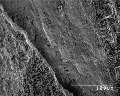
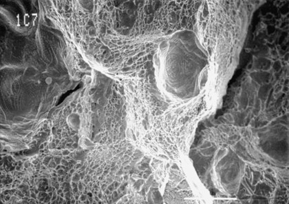
Alloys undergo brittle fracture or ductile fracture, depending on a variety of factors, such as composition, microstructure, temperature, and strain rate. Figure 17-8 illustrates the appearance of a brittle fracture surface for a carbon steel rotary endodontic instrument subjected to torsional loading. In contrast, Figure 17-9 presents a ductile fracture surface for a gold casting alloy specimen that had been loaded to failure in tension. The ductile fracture surfaces of metals are characterized by a typical rupture morphology, where failure has occurred because of the coalescence of microvoids that typically form at impurity particles during the later stages of permanent deformation. The dimpled rupture pattern reflects a map of the local stress field, which represents a characteristic appearance for bending and torsional fracture surfaces of rotary endodontic instruments that are fabricated from stainless steel.
 Critical Question
Plastic Deformation Without Dislocation Movement
An alternative mode of permanent deformation in metals is twinning. Twinning refers to the atomic arrangement within a crystal where a region of the crystal takes on a different crystallographic axis orientation from the rest of the crystal; the structures on either side of the boundary (between the two different orientations) are crystallographically identical as if they are reflections cross across a mirror plane. The boundary is called a twinning plane (Figure 17-10, A). The portion having a lattice orientation that is different from the original orientation is called a twin. Twinning can occur in a metal either during solidification as shown in Figure 17-10, A, or as a result of being stressed to a state of plastic deformation (Figure 17-10, B).
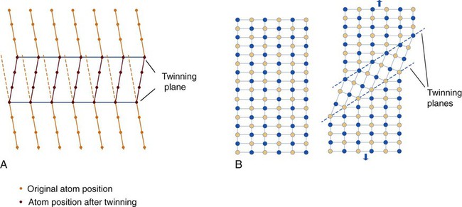
The stress needed to twin a crystal tends to be higher than that required for slip (see Figure 17-1). Therefore, slip is the normal deformation mechanism. Twinning is the favored mechanism at high strain rates and at low temperatures rather than dislocation movements in metals having relatively few slip systems. One should note that plastic deformation by twinning is merely a reorientation of the lattice, and that although the atoms in the twinned portion have moved, their positions relative to each other remain unchanged. On the other hand, plastic deformation by slip occurs along individual lattice planes for which the position of atoms relative to each other has changed.
Twinning has significance for deformation of α-titanium alloys, which are highly important for some dental implants and are gaining interest for cast restorations. In α-titanium the ratio of lattice parameter (c) in the perpendicular direction to the basal plane and the lattice parameter (a) in the basal plane (see Figure 2-8), which is known as c/a ratio, is slightly less than the ideal value of 1.633 for the hcp structure, which results in additional slip planes and the tendency to readily undergo twinning. Twinning is also the mechanism for reversible transformation between the austenitic and martensitic structures in nickel-titanium orthodontic wires, which has considerable clinical significance.
Application of Wrought Metal IN Dentistry
The mechanical properties that enable orthodontic wires to move the teeth to a more desirable alignment are the force the wire delivers and the working range. As demonstrated by a cantilever beam (Figure 17-11), for a given design with known elastic modulus (E), the elastic deflection of the beam is proportional to the force applied. The same relationship also shows that for a given elastic deflection, the force needed to maintain that deflection is proportional to the elastic modulus of the material. A properly designed orthodontic appliance applies forces to the teeth. As the teeth move, the deflection of the device decreases. In response to the reduction in elastic deflection of the appliance, the level of force applied to the teeth is gradually reduced below the threshold level. When this happens, the appliance must be reactivated to increase the force level to its original value.
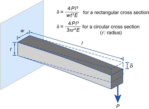
Elastic deflection of a cantilever beam under a load reflects the extent of tooth displacement that the designed appliance can deliver. The maximal amount of force a design can deliver is slightly less than the force needed to cause permanent deformation of the design; therefore, the greater the proportional limit of the wire, the higher the elastic deflection that the wire can deliver. The maximal elastic deflection the wire exhibits is called the working range. An obvious benefit of wrought wires is that they have a greater working range than their cast counterparts. Large elastic deflections are clinically desirable for orthodontic wires. The relationship in Figure 17-11 shows that for a g/>
Stay updated, free dental videos. Join our Telegram channel
VIDEdental - Online dental courses


