Section 5: Future Directions and Dilemmas
Chapter 16
Computer-Assisted Implant Dentistry: Possibilities and Limitations
INTRODUCTION
Implant-supported restorations have become an increasingly common treatment option for edentulous and partially edentulous patients worldwide. The number of implants placed has been increasing every year in the United States. With developments in regenerative techniques and materials, implant placement has been made possible even in patients with bone deficiencies that were previously considered unsuitable for implants. In the early years of dental implantology, implants were placed based on available residual bone. Many studies have shown that implant placements disregarding prosthetic and biomechanical demands leads to compromised definitive prosthesis with jeopardized occlusal scheme, poor aesthetics, and unfavorable biomechanics, even though implants were osseointegrated (Stanford 1999, Kopp, Koslow and Abdo 2003; Duff and Razzoog 2006; Widmann and Bale 2006; Azari and Nikzad 2008a). Implants inclined to a buccal or lingual position are not working in their long axes and are exposed to detrimental lateral forces creating biomechanical problems and even breakages (Rangert et al. 1995; Stanford 1999; Azari and Nikzad 2008a).
To meet functional and aesthetic demands, a philosophy of prosthetic-driven implant dentistry had been adopted as a treatment modality, which combines functional and aesthetic concepts. In prosthetic-driven implant placement, diagnostic casts and diagnostic wax-up of the prosthetic restoration guide the position of implants (Garber 1996; Widmann and Bale 2006). With the concept of “prosthetic-driven implantology,” both the available bone and teeth to be replaced were taken into consideration.
Developments in computer technology have changed diagnostic and surgical possibilities in dental implant dentistry. In modern dental implantology, the goal is not only to improve the precision and predictability of implant placement but also to change an invasive surgical protocol to a minimally invasive procedure and eventual immediate loading with less surgical time (Katsoulis, Pazera and Mericske-Stern. 2009). Preoperative planning of the number of implants to be placed, their size, position, inclination, has been made possible with developments in imaging systems and software programs, and this allows the dental implant surgeon to concentrate on the patient and surgery itself while also shortening the surgical time (Vercruyssen et al. 2008).
In this chapter, we will discuss the current status of computer-assisted implant dentistry, with all its possibilities and limitations. We will first describe what prosthetic-driven implantology means and then will talk about radiographic methods, with an emphasis on computerized tomography (CT) and software planning. A review of surgical guides; a description of advanced computer-assisted design (CAD), computer-assisted manufacturing (CAM), and navigation techniques; and indications and limitations of flapless surgery will be discussed. We will end this chapter with a case report where we combined virtual implant planning with conventional implant surgery.
PROSTHETIC-DRIVEN IMPLANTOLOGY
Prosthetic-driven implantology (PDI) is a modality that combines functional and aesthetic concepts of implant dentistry. In this concept, dental implants are placed according to prosthetic demands. To achieve this goal, the planned prosthesis is brought into the CT images. This way, implant planning takes into account both the jaw bone anatomy and the planned superstructure, which improves the biomechanics and the aesthetics. It is important that the implant axes coincide with the teeth of the fixed denture and fall within the circumference of the occlusal plane of the tooth (Sethi and Sochor 1995; Becker and Kaiser 2000, Vercruyssen et al. 2008, Azari and Nikzad 2008a).
In the early days of implant dentistry, clinicians who believed in the prosthetic-driven implantology concept used wax-up prostheses and/or surgical templates made on hard gypsum surfaces of master casts. To overcome the problem of transferring the prosthetic plan to the operative site, customized radiographic and surgical templates have become a routine part of treatment (Pesun and Gardner 1995; Garber 1996; Becker and Kaiser 2000). However, after a while, the hard surface of casts was found not to equal the soft tissue surface of the oral cavity. Templates fabricated on the diagnostic casts without knowledge of the exact anatomy below the surface was also found to be unreliable (Lal et al. 2006; Widmann and Bale 2006; Azari and Nikzad 2008a). It was soon understood that this type of template cannot be used during radiographic pre-evaluation of bony structures, and this precludes “show-through” of the proposed teeth in the radiographs (Basten 1995; Wat et al. 2002). Working on the subject instead of casts led to double-purpose templates, which can be used not only for radiographic examination and evaluation of the patient but also during surgery and placement of the implants (Cehreli, Aslan and Sahin 2000). Before three-dimensional imaging came into play, conventional dental panoramic tomography and plain film tomography were usually performed with the patient wearing a radiographic template with integrated metal spheres at the position of the wax-up. Based on the magnification factor and the known dimensions of the metal sphere, the depth and dimensions of the implants could be estimated. In fact, double-purpose templates may somewhat relieve the problem of directing the implant to a good position. However, it was soon well established that all x-ray transmission–based radiographs suffer the limitation of being two-dimensional projections of complex, intrinsically three-dimensional anatomy. Conventional radiography has important diagnostic limitations such as expansion and distortion, setting errors and position artifacts (Azari and Nikzad 2008a). Soon after, three-dimensional imaging was introduced, and the prosthetic-driven implantology concept was adapted to three-dimensional imaging.
IMAGING METHODS IN DENTISTRY
Two-Dimensional Radiography
The most commonly used radiographs available to dentists are periapicals, bitewings, and panoramic radiographs. They are useful in providing diagnostic information regarding identifiable landmarks, pathology, and initial estimates of bone availability. They are also readily accessible, simple, and emit acceptable amounts of radiation. Even though in the early days of dental implantology dental surgeons relied on two-dimensional radiography, the use of these radiographs are limited in advanced implant treatment planning. Because of a lack of three-dimensional viewing, radiographs provide limited information regarding anatomical limitations, such as maxillary sinus, bone height estimate, bucco-lingual dimensions, concavities, and inferior alveolar nerve proximity (Jabero and Sarment 2006). Linear tomography can be used in planning of dental implants for a bucco-lingual estimate of bone, but it does not provide accurate imaging; nor does it produce volume images of adjacent structures for precise planning and placement in advanced cases.
Introduction of Three-Dimensional Imaging to Implant Dentistry
One of the most important technological advancements that dramatically enhanced the clinician’s ability to diagnose and plan dental implants has been the computed tomography (CT) scan. Although computerized axial tomography (CAT) scans have been available for medical use since 1973 (Hounsfield 1973), it was not until 1987 that this innovative technology became available for dental applications (Schwarz et al. 1987a, b). One of the major features that draw the dentist’s attention to CT technology is the ability to avoid the superimposition of structures, which makes CT scans more desirable than conventional radiography as a morphometric tool (Azari and Nikzad 2008a).
CT is the most advanced radiographic methodology for dental implant diagnosis (Todd et al. 1993; Gher and Richardson 1995; Jacobs et al. 1999). This technology is different from previous methods in that it includes a radiographic source with circular movements, a digital receptor, and advanced software reformatting processes. The result is a series of axial images that the computer can reformat to provide images in cross-sectional, panoramic, and three-dimensional views. Contrary to other radiographs, there is no exposure onto a radiographic film. Instead, computer files can be seen using software (Jabero and Sarment 2006). CTs are used for the following purposes (Iplikcioglu, Akca and Cehreli 2002):
1. To determine the quality and the quantity of bone
2. To evaluate the potential sites for implant placement
3. To evaluate intra-osseous pathologies
4. To follow up regions where extensive surgery is performed.
CT is now a very common imaging technique. For maxillofacial applications, dedicated software was developed capable of reformatting the data of the axial slices into panoramic images and multiplanar cross-sectional images (Schwarz et al. 1989). Today, the availability of three-dimensional planning software, which, furthermore, allows a reliable transfer of the virtual implant planning into the surgical field through drilling templates, helps the surgeon to achieve an adequate oral implant placement (Van Steenberghe et al. 2002).
Advantages of CT
One of the most promising advantages of CT is its high level of accuracy in comparison to other modalities. There is almost no magnification error caused by geometric distortions, whereas such errors are common in conventional dental radiographs. Some researchers have compared the degree of accuracy and distortion of conventional radiographs and CT (Jemt 1993; Bahat 1993). According to these studies, the least accurate methods were panoramic views (17%), conventional tomography (39%), and peri-apical views (53%), whereas the CT has accuracy as high as 95% (Bassi et al. 1999). Sonick et al. (1994) also compared accuracy of two-dimensional and three-dimensional imaging. The differences between the actual caliper and radiograph were as follows:
- Periapical: 0.5–5.5 mm/average 1.9 mm
- Panoramic: 0.5–7.5 mm/average 3.0 mm
- CT: 0–0.5 mm/average 0.mm
The radiographic distortion differences are:
- Periapical: 8–24%/average 14%
- Panoramic: 5–39%/average 23.5%
- CT: 0–8%/average 1.8%
CT also has ability to measure bone density. Also in CT, multiplanner reformatting allows one to reformat a volumetric dataset in axial, coronal, and sagittal cuts and to build multiple cross-sectional and panoramic views (Schwarz et al. 1987a, b). For the time being, these advantages make CT the most precise and comprehensive radiological technique for dental implant planning.
From the introduction of modern implantology, it was proposed that the success rate of dental implant therapy is influenced by both the quality and the quantity of bone (Ulm et al. 1999; Azari and Nikzad 2008a), and clinical reports have indicated that implant prognosis is significantly affected by bone quality (Jaffin and Berman 1991; Jemt et al. 1992). Conventional dental radiographs, including periapical, panoramic, lateral cephalometric, or even conventional tomography are less useful for diagnosing the bone density.
Concerns Regarding High-Dose Radiation with CT
Studies have demonstrated that the use of CT is associated with significantly higher doses of radiation compared to conventional radiography (Ekestubbe et al. 1993; Frederiksen, Benson and Sokolowski 1994, 1995). The American Academy of Oral and Maxillofacial Radiology (AAOMR) and the European Association for Osseointegration (EAO) recommend the cross-sectional imaging modality for patients receiving implants (Tyndall and Brooks 2000; White et al. 2001; Harris et al. 2002). On the other hand, CT scanner systems have been developed to such an extent that dramatic advances have been. As scanners improved in the speed of image acquisition, so did their versatility. Multiphase scanning with well-defined phases can now be achieved where larger body volumes may be scanned with little relevant time penalty, at a very low possible dose of radiation, and with rapid screening in a variety of guises (Dawson 2004; Azari and Nikzad 2008a).
Cone-Beam Computed Tomography
Continued advancements in CT scanning technology have led to the development of cone-beam CT (CBCT). The cone-beam technique requires only a single rotation to capture the entire object. Scanning time is reduced to 10–40 seconds. While the rotation takes place, a high number of projections are rapidly captured. Later, a reconstruction algorithm renders cross sections. CBCT has become the most advanced type of radiographic technique when compared to traditional spiral and helical CT, based on the following advantages: reduced cost; decreased radiation; decreased scanning time, resulting in less patient movement; smaller and more convenient machinery; and more precise imaging (CBCT: 0.2–0.4 mm slices; CT: 0.5–1 mm) (Jabero and Sarment 2006). CBCT requires 30–90 times less radiation than the conventional CT scanner (Van der Zel 2008). Therefore, the introduction of CBCT, offering imaging at low dose and relatively lower costs, has increased the applicability and feasibility of three-dimensional–based presurgical planning. The surgeon can properly position implants in a virtual reality (Vercruyssen et al. 2008). Data acquisition, slice thickness, and interval of the reconstruction can determine the imaging resolution. One of the characteristics of these CBCT systems is being able to select the region of interest in accordance with the clinical demands (Guerrero et al. 2006).
CT Scanning Appliances
To address the requirements of the concept of prosthetic-driven implantology, some type of radio-opaque CT scan template incorporating information about the position, occlusion, form, and contour of missing teeth gives the data that can be viewed in relationship to the underlying structures (Israelson et al. 1992; Klein, Cranin and Sirakian. 1993; Verde and Morgano 1993; Basten 1995; Borrow and Smith 1996; Amet and Ganz 1997; Azari and Nikzad 2008a). In this way it will be possible for a restorative dentist to visualize the location of planned implants from an aesthetic and biomechanical standpoint. There are three generations of scanning appliance designs described (Rosenfeld, Mandelaris and Tardieu 2006, Azari and Nikzad 2008a).
1. A barium-coated silhouette of the proposed prosthesis
2. A radiopaque tooth from the vacuum-formed template filled with acrylic resin/barium
3. The Tardieu Scannoguide, which is a differential barium gradient–scanning appliance.
The Tardieu Scannoguides allow the clinician to transfer the prosthetic outcome and define the soft tissue on the CT. This offers the potential for fabrication of specialized surgical drilling guides for flapless implant surgery (Rosenfeld, Mandelaris and Tardieu 2006).
It is necessary to have some degree of expertise to correctly interpret the CT’s printed images, and this is not easy in routine dental practice. The images obtained from CT are really two-dimensional, which requires a process of mental integration of multiple sections by the observer to derive three-dimensional information (Gillespie and Isherwood 1986). These two-dimensional views are easier to show on the computer, but they are basically a digitized version of printed images. To overcome these obstacles, we need systems that allow simultaneous visualization of two-dimensional reformatted images as well as three-dimensional–derived bone surface representations. In this way we have the opportunity for interactive placement of implant-like CAD models on the images obtained from CT data (Azari and Nikzad 2008a).
FROM IMAGES TO PRACTICE
Virtual Implant Planning
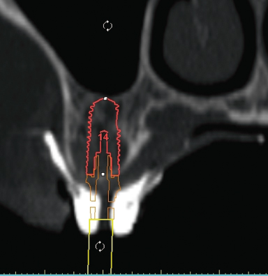
By using software programs, clinicians have the ability to view and interact with the CT scan data to place the implant presurgically and visualize the restorative implications virtually. It is possible to reformat the CT scan data to provide an accurate three-dimensional view of the anatomy of the bone in which the clinician can interactively introduce implant planning into the CT images (Jabero and Sarment 2006; Azari and Nikzad 2008a). Today, many specific software programs have been developed for planning dental implant surgery in the maxilla and mandible. Specific software applications have been developed that can directly import Digital Imaging and Communication in Medicine (DICOM) data into a diagnostic and interactive treatment planning tool (Vercruyssen et al. 2008). All reconstructed images, as well as three-dimensional virtual reconstructions, are visible, and measurements of bone height, width, and density are always available. Tracing of anatomical landmarks such as the mandibular nerve is possible, and placement of virtual implants to select an appropriate size and position is simple (Jabero and Sarment 2006). These software programs allow the clinician to plan the best position, angulation and size of the implant relative to the designed prosthesis and proximity of vital structures (Figure 16.1). After implants are virtually placed in the best position, it is possible to see the bone density around the implants. This allows the implant surgeon to have an idea of what the primary stability would be; therefore, the surgeon can plan final drill sizes to get best primary stability since surgical guides make it difficult to feel bone density during drilling. Most of the surgical guides are designed for medium bone density, which could be hard to have in posterior maxilla.
Figure 16.1 Virtual implant planning using software to verify implant size and relationship to prosthesis and vital structures.
Transferring Computer Plan into Surgical Site
Transferring the computer plan into actual patient treatment has been made possible first by the revolutionary CAD/CAM techniques.
There are mainly two guided-surgery systems: (1) static guides and (2) dynamic systems.
Static Surgical Guides
Traditional surgical guides are acrylic appliances used during surgery to place implants properly by conveying the decisions for implant positions made during the diagnostic and treatment planning stages. These templates are made by duplicating the diagnostic teeth or reproducing the long axis of future restorations using. However, providing a surgical guide does not guarantee the recommended location of implants because bone may not be available to accommodate the desired positions or anatomical limitations. Use of traditional surgical guides designed from stone models with the assistance of periapical, bitewing, and panoramic x-rays can lead to multiple limitations for advanced implant guidance that may compromise the overall execution of treatment (Jabero and Sarment 2006). Therefore, radiographic surgical guides and CAD/CAM technology came into play.
CAD/CAM Surgical Guide
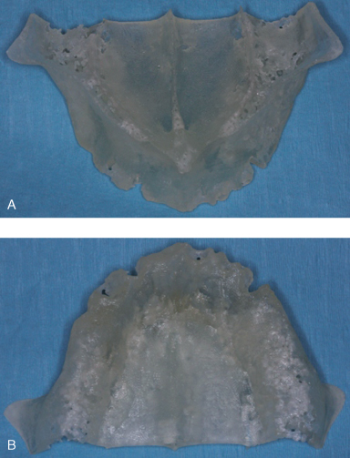
To address concerns inherent in traditional surgical guides, further computer software programs have been developed using sophisticated modalities of CAD as well as fabrication of surgical guidance models with CAM. CAD/CAM technique was the first attempt to bring virtual planning into reality. Early data regarding the incorporation of CAD/CAM techniques into implant dentistry were for eliminating the surgical bone impression phase of the subperiosteal implant modality (Truitt et al. 1988). With CAD/CAM technology, for the first time it was possible to physically feel the area of interest, such as maxilla or mandible. Physical models are very helpful because they offer the opportunity to hold the model in the hand, which provides the clinician with a direct understanding of complex anatomical details that otherwise cannot be obtained from imaging on a screen (Figure 16.2).
Figure 16.2 (A and B) Physical models of maxilla.
CAM methods for implant applications include three-dimensional printing techniques or computer-driven model drilling. These guides are used during surgery to improve accuracy, confidence, and rapidity. CAD/CAM surgical guides require CT scanning and computer software programs that assist in diagnosis and planning. Once the CT data and implant planning procedures have been determined, surgical guide fabrication can be manufactured in a variety of three-dimensional printing or computer-driven drilling systems (Jabero and Sarment 2006).
Three-Dimensional Printing Guides—Rapid Prototyping
The layer data format of CT scanners quickly prompted the realization that it may be possible to convert the data to be compatible with rapid prototyping (RP) machine requirements. By definition, RP refers to the fabrication of three-dimensional physical models directly from a CAD model. Currently, the most developed CAD/CAM surgical guide methods use three-dimensional printing. The model is built layer by layer according to three-dimensional data (Jacobs 1992; Cooper 2001). This type of mechanical prototyping is capable of quickly fabricating complex shaped, three-dimensional parts directly from CAD models. This may differ from just milling, which has been a routine procedure in normal CAD technology (Azari and Nikzad 2008a).
One of the three-dimensional printing methods called stereolithography uses a laser-cured resin model (SurgiGuide, CSI Materialise, Glen Burine, MD) (Ganz 2003). The process begins with the patient receiving a CT scan. It is preferable to provide a scanographic template. Implant planning is performed with final prosthetic planning being visible. After acquisition, the CT files are submitted to the company, and reformatting is performed. The implant planning team then receives a small proprietary file via e-mail that contains all images. Planning takes place using software (Sim-Plant, CSI Materialise, Belgium), and alterations can be made until a satisfactory treatment plan is agreed upon. The planning files can then be submitted by e-mail for processing. For tooth-supported CAD/CAM guides, a stone model must also be mailed together with the file because a separate optical scanning of the model is necessary. The rapid modeling process can then begin, using a computer-driven laser that cures a thin layer of liquid polymer, followed by additional stacked layers, resulting in a three-dimensional model. Once the process is complete, metal sleeves are inserted into the guide, providing guidance for implant placement. This method also produces a three-dimensional template of the anatomical model. A series of guides are produced to accommodate drill size (Jabero and Sarment 2006).
There are many software programs in the marketplace for CT-based modeling and RP-made surgical templates, such as Simplant, Implant 3D, Vimplant, NobelGuide, Implant Master, CADImplant, Galileos, 10DR, and DDent/DDent plus I.
Computer-Driven Drilling
Another method of CAD/CAM surgical guide fabrication uses computer-driven drilling without producing three-dimensional models. One of these systems (CADImplant, CADImplant Inc., Medfield, MA) uses such drilling. The process begins with the fabrication of a surgical template from prosthetic study mod/>
Stay updated, free dental videos. Join our Telegram channel
VIDEdental - Online dental courses


