Dental Amalgams
Amalgam Alloys
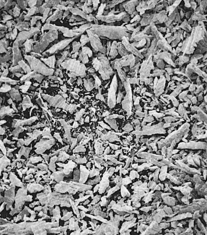
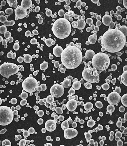
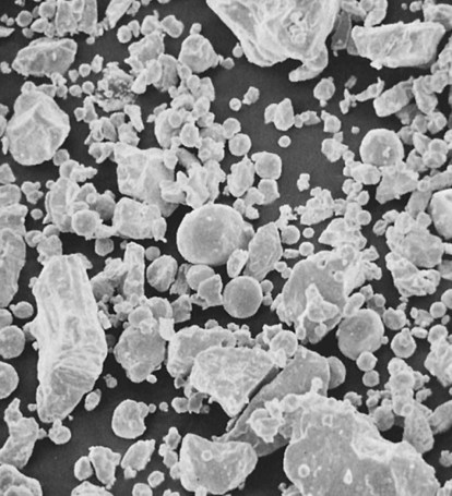
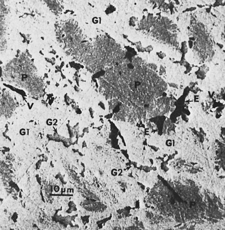
Before these alloys are reacted with mercury, they are known as dental amalgam alloys or alloys for dental amalgam. They are usually provided as (1) irregularly shaped particles (Figure 15-1) produced by milling or lathe-cutting a cast ingot of the amalgam alloy, (2) as spherical particles (Figure 15-2) produced by atomizing the liquid alloy in a chamber filled with inert gas, or (3) as a mixture of both lathe-cut and spherical particles (Figure 15-3).
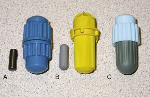
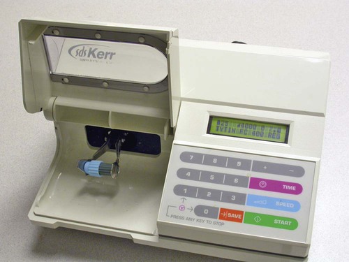
Originally, the dentist dispensed alloy powder and mercury in a mortar and mixed them together with a pestle by hand. The process of mixing is called trituration. Later, the powder was compacted in the form of pellets, which were dispensed along with mercury in a reusable capsule with a pestle (Figure 15-4, A) and triturated by a power-driven triturator or amalgamator (Figure 15-5). Today, disposable amalgam capsules are widely available (Figure 15-4, B & C). Each capsule contains a predetermined amount of alloy powder and mercury in a sealed pouch, and the capsule is sealed to prevent evaporation of the mercury.
Composition
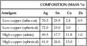
The introduction of a higher copper content in amalgam alloys marked a significant change in the properties of amalgams. It is now customary to classify amalgam alloys as either low-copper (conventional) or high-copper alloys (Table 15-1). In both types, the major components of the alloys are silver and tin.
TABLE 15-1
Composition of Some Typical Commercial Amalgam Alloys
| COMPOSITION (MASS %) | ||||
| Amalgam | Ag | Sn | Cu | Zn |
| Low copper (lathe-cut) | 70.3 | 25.9 | 2.8 | 0.9 |
| Low copper (spherical) | 72.0 | 25.0 | 3.0 | – |
| High copper (admix) | 69.5 | 17.7 | 11.8 | 1.0 |
| High copper (spherical) | 61.0 | 26.0 | 13.0 | – |
The Silver-Tin System
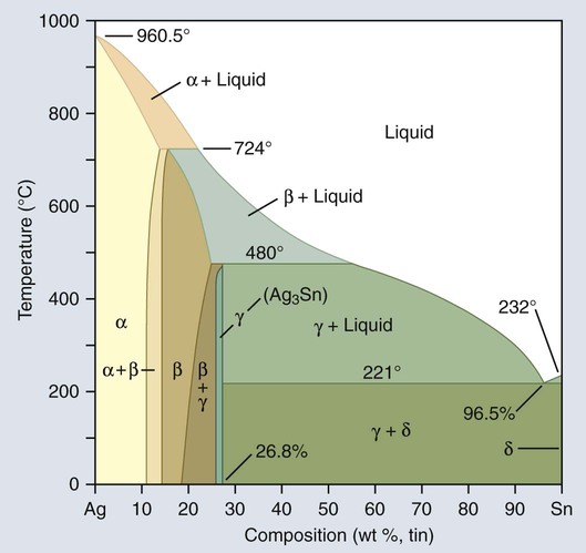
Figure 15-6 is an equilibrium-phase diagram of the silver-tin alloy system. Conventionally, starting from the left of the phase diagram, each phase is designated with a Greek letter in alphabetical order from 0% Sn to 100% Sn. The ratio of silver to tin in Table 15-1 shows that amalgam alloys have a narrow range of compositions, falling within the β + γ and the γ phases of the diagram shown in Figure 15-6.
Amalgamation
Low-Copper Alloys
The main reactions of low-copper alloy produce alloy phases including the body-centered cubic Ag2Hg3 (γ1) phase and the hexagonal Sn7-8Hg (γ2) phase (Figure 15-7). Both phases are designated as the γ phase because they happen to be the third phase of the respective Ag-Hg and Sn-Hg systems. Since the solubility of silver in mercury is much lower than that of tin, the Ag2Hg3 phase precipitates first and is designated as γ1, whereas the Sn7-8Hg phase precipitates later and is designated as γ2. There is evidence from x-ray diffraction and thermal analyses of set amalgam that a δ phase, which is richer in mercury than γ2, is present in low-copper alloy instead of γ2. The existence of γ2 or δ phases in low-copper amalgams remains an unresolved question. For the purpose of this discussion the Sn-Hg phase is designated as γ2 in this chapter.
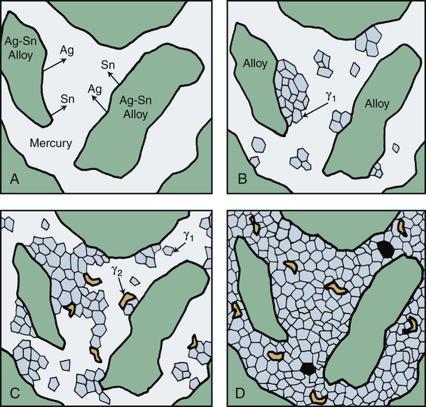
The low-copper alloy is usually mixed with mercury in a ratio of about 1 : 1. This is an insufficient amount of mercury to consume the original alloy particles completely; consequently, unconsumed particles are present in the set amalgam. Thus, a typical low-copper amalgam is a composite in which the unconsumed particles are embedded within γ1 and γ2 phases. The sequence of amalgamation of the silver-tin alloy is shown schematically in Figure 15-8.
A reaction between Cu3Sn (ε phase) and γ2 also occurs and yields Cu6Sn5 (η′ phase). Because of the low copper content, a majority of γ2 remains. Figure 15-9 illustrates the features found in a typical microstructure of amalgam made from a lathe-cut, low-copper alloy. As described later, the addition of more than 6% of copper by weight can reduce or eliminate the γ2 phase by formation of the Cu-Sn phase.
High-Copper Alloys
Admixed Alloys
When mercury reacts with an admixed powder, silver in Ag-Cu spheres and silver and tin from Ag-Sn particles dissolve into the mercury. Whereas both γ1 and γ2 crystals form, as in lathe-cut alloys, the tin in mercury diffuses to the surfaces of the Ag-Cu alloy particles and reacts with the copper to form a layer of η′ phase crystals on the surface. The η′ layer on the surface of Ag-Cu alloy particles also contains γ1 crystals, since γ1 and η′ phases form simultaneously. As in the low-copper amalgams, γ1 is the matrix phase (i.e., the phase that binds the unconsumed alloy particles together). In this reaction, the γ2 phase does form along with the η′ phase but later reacts with copper from Ag-Cu particles, yielding additional η′ phase (the secondary solid-state reaction in Figure 15-7). The γ2 phase can be eliminated with at least 11.8% of copper by weight in the alloy powder.
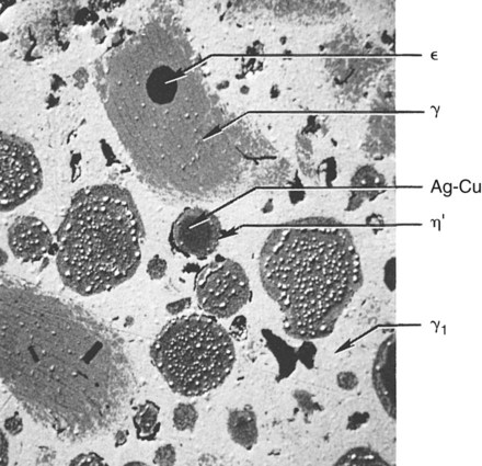
Figure 15-10 illustrates the microstructure of an admixed amalgam. Included in this structure are the γ phase particles, Ag-Cu particles, ε particles, the γ1 matrix, and η′ reaction layers. In some admixed amalgams, a small number of the η′ crystals are also found amid the γ1 matrix.
Single-Composition Alloys
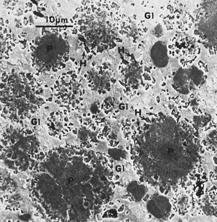
When triturated with mercury, silver and tin from the Ag-Sn phases dissolve in mercury. Very little copper dissolves in mercury. The γ1 crystals grow, forming a matrix that binds together the partially dissolved alloy particles. The η′ crystals are found as meshes of rodlike crystals at the surfaces of alloy particles, dispersed in the matrix. In most single-composition amalgams, little or no γ2 forms (Figure 15-7). Figure 15-11 shows the microstructure of a typical single-composition amalgam. This structure includes unconsumed alloy particles (P), γ1 grains (G1), and η′ crystals (H).
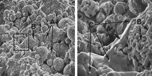
Figure 15-12, A, shows a scanning electron micrograph of a high-copper single-composition amalgam fractured a few minutes after condensation when the amalgamation reaction was still taking place. Two kinds of crystals are seen on the surface: polyhedral crystals (γ1), shown by arrow A, between the unconsumed alloy particles, and meshes of η′ rod crystals, shown by arrow B, for the unconsumed alloy particles.
Figure 15-12, B, shows details of the marked areas in Figure 15-11, A. In addition to a mesh of η′ crystals (arrow B), which formed on an unconsumed particle, η′ rods (arrow C) are seen embedded in a γ1 crystal (A). Meshed η′ crystals on unconsumed alloy particles may strengthen bonding between the alloy particles and γ1 grains, and η′ crystals dispersed between γ1 grains may interlock γ1 grains. This interlocking is believed to improve the amalgam’s resistance to deformation.
Clinical Manipulation of Amalgam for Restorations
Mechanical Trituration
Triturators
The main mixing mechanism of a mechanical triturator is a reciprocating arm that holds the capsule under a protective hood. The purpose of the hood is to confine mercury that might escape into the room or to prevent a capsule from being accidentally ejected from the triturator during trituration. A commonly used older model is a single-speed device with an automatic timer for controlling the length of the mixing time. Later models have multiple speed settings. A modern triturator is often microprocessor controlled (Figure 15-5) and contains preset trituration programs for a number of materials. It can also be programmed by the operator to include other materials. A cylindrical metal or plastic piston of smaller diameter than the capsule is inserted into the capsule, and this serves as the pestle (Figure 15-4, A & B). Spherical alloys often do not need a pestle (Figure 15-4, C).
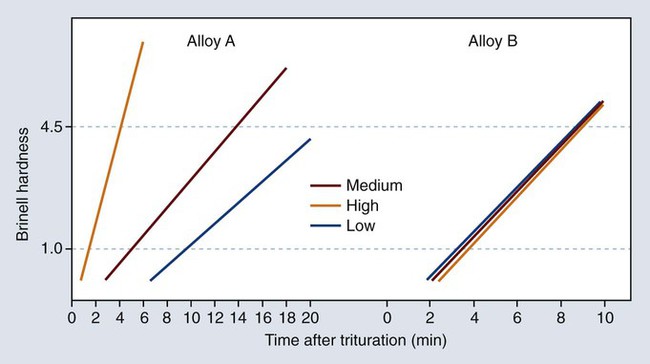
Manufacturers often provide a list of recommended time schedules and speed settings for their alloys and various types of triturators. Because of the speed variations in triturators, the schedule should serve only as a rough guide. Dentists and assistants can adjust the amalgamation time required to attain a mix of correct consistency. For a given alloy and mercury/alloy ratio, increased trituration time and/or speed shorten the working and setting times. In addition, alloys differ in their sensitivity to trituration time (Figure 15-13).
Consistency of the Mix
The proper time of mixing can be determined by observing the consistency of the mix. For example, the very grainy mix (Figure 15-14, A) indicates undertrituration. Not only will the amalgam restoration made from this mix be weak, but also the rough surface left after carving of the granular amalgam will increase its susceptibility to tarnish. If the trituration has produced an amalgam of the general appearance shown in Figure 15-14, B, the strength will be optimal and the smooth carved surface will retain its luster long after polishing. Because of the friction between particles during trituration, such an amalgam mix should be warm (not hot) when it is removed from the capsule. This will have no effect on the physical properti/>
Stay updated, free dental videos. Join our Telegram channel

VIDEdental - Online dental courses


