Standard Analytic Model Planning for Orthognathic Surgery
• Controversies Surrounding Model Planning for Orthognathic Surgery
• Standard Facial Records for Orthognathic Surgery
• Key Measurements Obtained via Direct Visual Examination to Define Planned Maxillomandibular Surgical Change
• Face-Bow Registration and Transfer to the Semi-Adjustable Articulator
• Use of the Erickson Model Table to Define the Spatial Orientation of an Articulator-Mounted Maxillary Unit
• Use of the Erickson Model Table to Define the Spatial Orientation of an Articulator-Mounted Mandibular Unit
• Separation of the Maxillary Cast from the Articulator Base
• Use of the Erickson Model Table Measurements to Reorient the Maxillary Cast
• Intermediate Splint Construction for the Positioning of the Maxilla During Operation
• Reorientation of the Mandibular Cast to Register the Final Occlusion
• Final Splint Construction for the Positioning of the Mandible During Operation
• Finishing of the Prefabricated Acrylic Splints
• Accuracy of the Described Analytic Model Planning Technique: Review of Study
Unlike most surgical procedures, orthognathic surgery involves not just the thorough medical assessment of the patient but also precise preoperative dental, radiographic, and facial aesthetic planning. The surgeon must carry out a detailed face-to-face examination of the patient to determine variations from normal (Fig. 13-1).
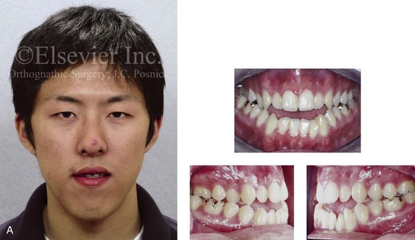
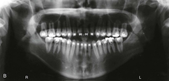
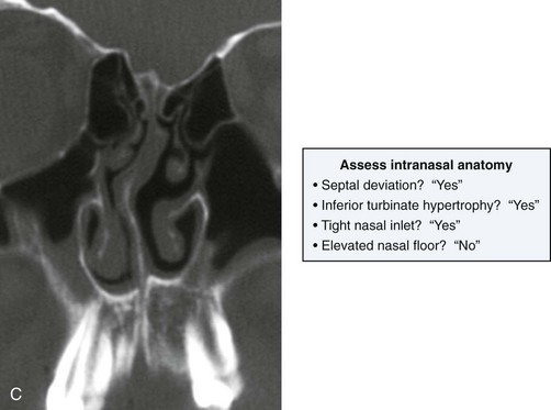
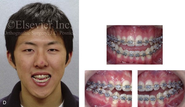
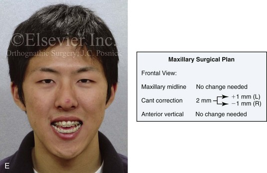
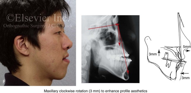
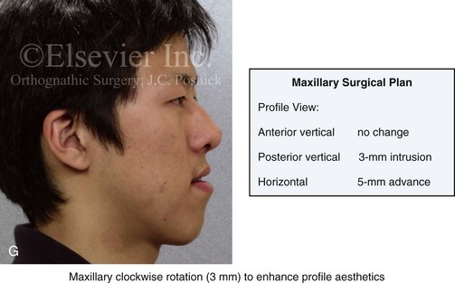
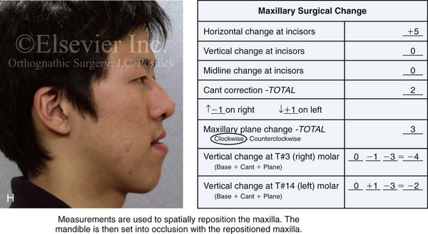
Figure 13-1 A 19-year-old man of Asian descent presented with a maxillary deficient and relative mandibular excess growth pattern. He has an Angle Class III anterior open bite with negative overjet malocclusion as well as a lifelong history of obstructed nasal breathing. The maxillofacial dysmorphology causes difficulties with speech, chewing, swallowing, breathing, and lip closure/posture, and it also negatively affects his facial aesthetics. The upper facial skeleton is symmetric and proportionate; the soft-tissue envelope is distorted but not malformed. There is a good range of motion of the neck and mandible without temporomandibular disorder. After evaluation, a comprehensive orthodontic and surgical approach was discussed and approved. Orthodontic (dental) decompensation required 10 months of active treatment. No extractions were required. Six weeks before surgery, the patient returned for a direct visual examination and the taking of records that included alginate impressions of the maxilla and mandible, centric bite registration, face-bow registration, and the transfer of the data to a semi-adjustable articulator. Decisions were made regarding critical measurements for the surgical repositioning of the jaws. The procedures carried out included the following: a Le Fort I osteotomy in segments (horizontal advancement, cant correction, arch expansion, and clockwise rotation); bilateral sagittal split ramus osteotomies (mandibular adjustment); osseous genioplasty (minimal vertical shortening and horizontal advancement); and septoplasty and inferior turbinate reduction. A, Frontal view in repose and occlusal views before treatment. B, A Panorex radiograph. This is useful to assess basic condylar morphology and to look for mandibular and dental pathology, including root resorption. C, The patient’s history of lifelong nasal obstruction—in combination with an intranasal speculum and a sinus computed tomography scan examination—confirms a deviated septum (bone and cartilage) and hypertrophic inferior turbinates. Both of these conditions required surgical correction to improve the airway. D, Frontal view with smile and occlusal views with orthodontic decompensation in progress. E, A frontal facial view confirms that the maxillary midline matches the upper facial midline; that there is a satisfactory lip–tooth relationship in repose and with smile; and that there is canting of the maxilla at the molars (2 mm) as compared with the upper face. F, Analysis of the facial profile and the lateral cephalometric radiograph before surgery provides useful information about facial height, incisor inclination, A-point to B-point relationship, maxillary and mandibular projection, and chin morphology. G, The direct visual examination of this patient in profile as well as Andrew’s analysis confirms the following: an advantage of horizontal advancement at the maxillary incisors (5 mm); no need for vertical change at the maxillary incisors; an advantage of 3-mm clockwise rotation of the maxillary plane (3-mm intrusion at the first molars); and no need for horizontal change at the mandibular incisors. Note that 5-mm horizontal advancement at the incisors will correct the negative overjet and that 3-mm clockwise rotation of the maxillary plane (intrusion at the first molars) will be helpful to restore profile aesthetics and to overcome maxillary incisor procumbancy. H, The planned maxillary surgical change is recorded on the orthognathic data sheet. These measurements will be used to spatially reposition and reorient the maxilla first on the articulator for intermediate splint construction and then at the time of Le Fort I osteotomy. During surgery, through sagittal split ramus osteotomies, the mandible will then be set into occlusion with the repositioned maxilla.
Immediate presurgical records include the following: 1) dental impressions of the maxilla and mandible 2) an accurate bite registration in centric relation (CR) 3) a face-bow recording of maxillary orientation in relationship to the condyles and the upper face and 4) the measurement of specific facial landmarks that includes deviations from normal (Figs. 13-2 and 13-3).
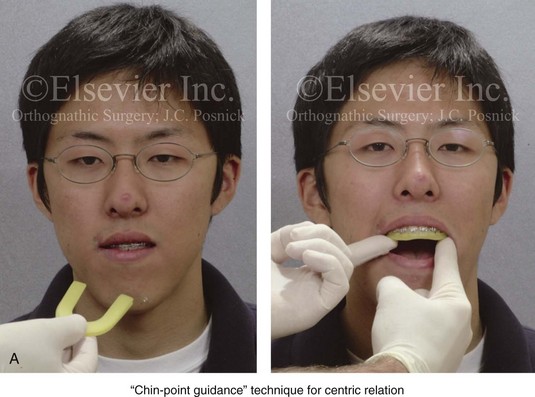
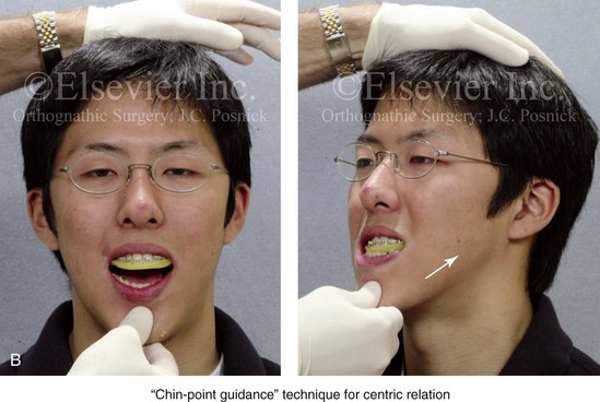
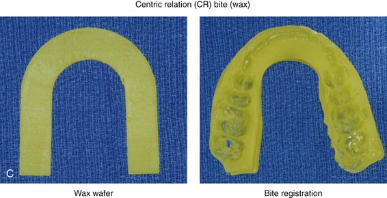
Figure 13-2 The chin-point guidance technique is used to capture (register) the centric relation bite. The patient is seated upright and in the natural head position. The chin-point guidance technique is accomplished by using one hand to apply pressure to the subject’s chin and the other hand to apply counter pressure to their occiput. This allows the clinician to apply posterior and superior “vectored” force on the anterior aspect of the mandible. By doing so, the condyles will be seated in a superior-anterior location within each glenoid fossa (i.e., centric relation). A, The registration of the patient’s maxillary occlusion into soft wax. B, Applying pressure to the chin with the patient’s muscles relaxed. The condyles are seated, and the mandible is rotated up until the teeth first occlude. It is essential to avoid a shift (slide) from the centric relation into a centric occlusion. This may occur in a patient with malocclusion if he or she is allowed to fully clench the teeth together. C, Wax wafer before and after bite registration.
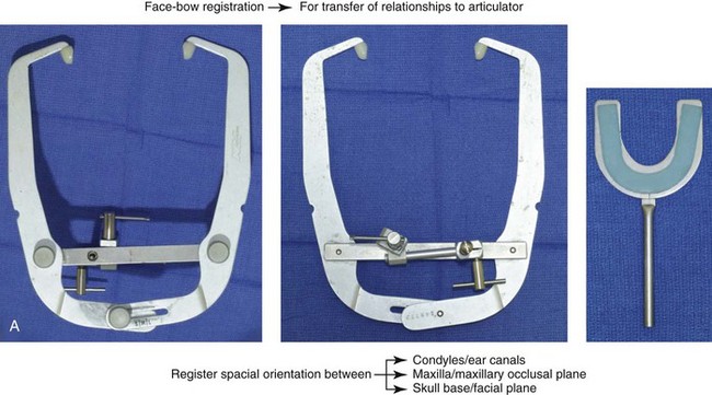
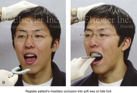
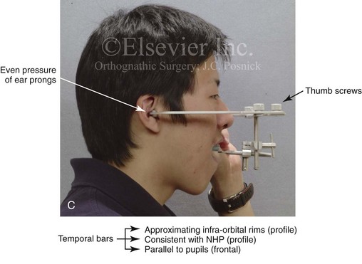
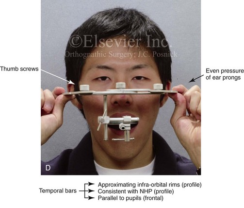
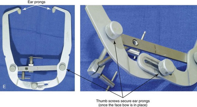
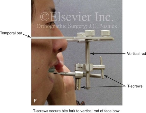
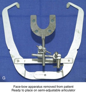
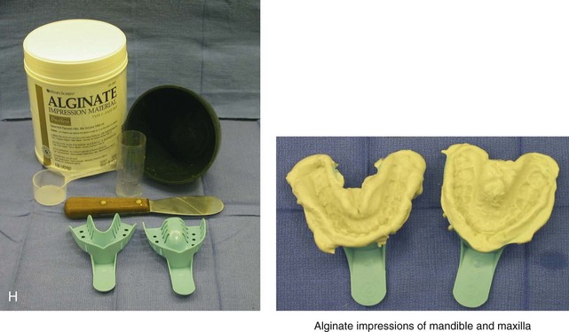
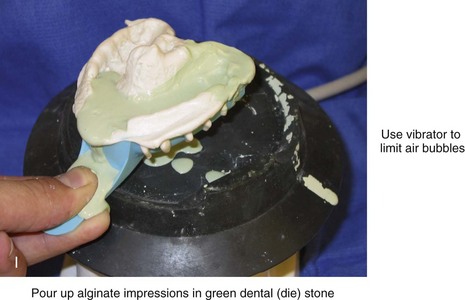
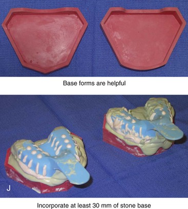
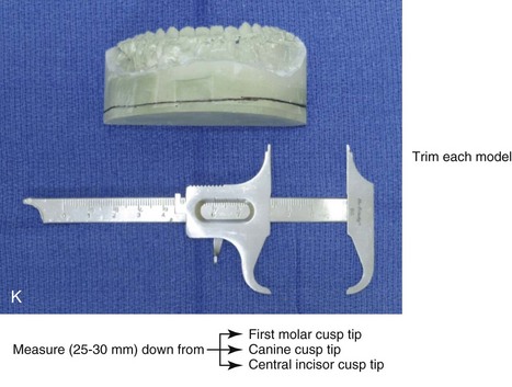
Figure 13-3 A, Bite fork with soft wax placed on the upper side is demonstrated. The face-bow apparatus is shown from both the bird’s-eye view and the worm’s-eye view. B, The patient’s maxillary occlusion is registered into soft wax on the bite fork. C, The face bow apparatus is held in place through even pressure of the ear prongs in each ear canal. The three thumbscrews are then tightened. D, The temporal bar is set parallel with the interpapillary line and consistent with the natural head position. E, A close-up view is shown of the thumbscrews that secure the ear prongs in place. F, T-screws secure the bite fork to the vertical rod of the face-bow apparatus. The T-screws are turned clockwise to secure the face bow after confirming that the temporal bar extensions are parallel to the interpupillary line (frontal view) and consistent with the natural head position (profile view). G, With the T-screws tight, the thumbscrews are loosened to release the face-bow apparatus from the patient. The face bow is now ready to place on the articulator. H, Impression trays are selected to fit the patient’s arch form. The alginate is mixed, placed in the trays, and then taken to the maxillary and mandibular arches, in turn. Negative impressions of the dentition are recorded in the alginate. I, The alginate impressions are “poured up” in green dental (die) stone. The use of a vibrator during this process will limit air bubbles. J, Base formers are useful when incorporating additional dental stone to achieve at least 30 mm of height for each dental cast. K, After the die stone is set (≈30 min), the models can be trimmed to achieve a consistent 25-mm base on the maxillary cast and a 30-mm base on the mandibular cast.
The maxillary model is mounted on a semi-adjustable articulator in accordance with the face-bow recording. The mandibular model is occluded to the mounted maxillary cast with the use of the CR bite1,2,14,17,18,21,30,52,62,63 (Fig. 13-4). The mounted dental casts are then used to complete model planning12,50 (Figs. 13-5 through 13-8). Splints made of acrylic are fabricated and used intraoperatively to further ensure the reliable execution of predetermined facial aesthetic and functional objectives (Figs 13-9 through 13-11).
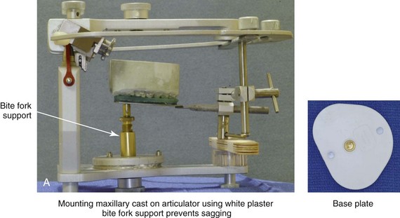
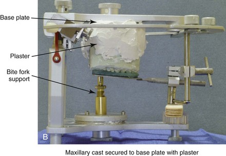
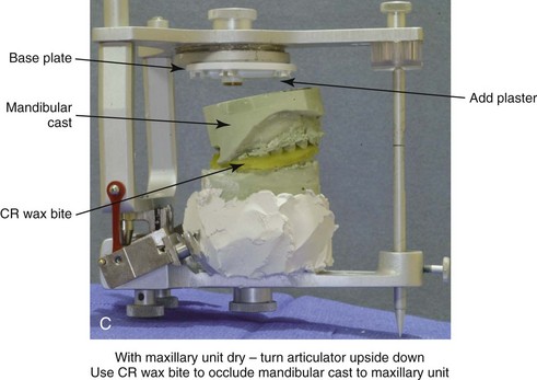
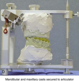
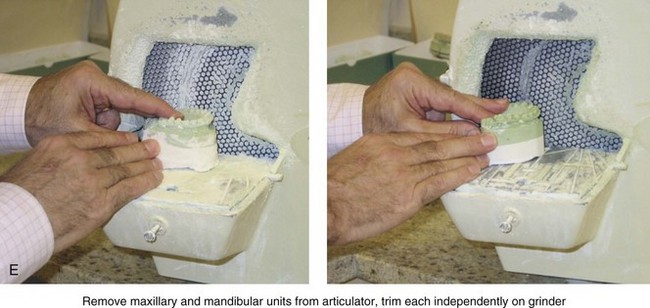
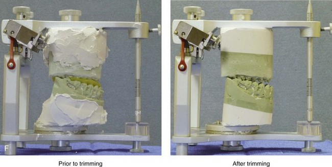
Figure 13-4 A, The trimmed dental casts are then mounted on the semi-adjustable articulator with the use of the face-bow apparatus. The temporal arms of the face bow are maintained parallel to the upper aspect of the articulator and the counter top. Base plates for the maxillary and mandibular units are secured to the articulation. A bite-fork support is useful to prevent the sagging of the face-bow apparatus when mounting the maxillary cast. B, The plaster is mixed and added in between the maxillary dental cast and the base plate. C, With the maxillary unit initially set (≈15 min), the articulator is turned upside down. The centric relation wax bite is occluded to the maxillary cast. The trimmed mandibular cast is then occluded to the other side of the wax bite. D, With the base plate secured to the articulator, the space that separates the mandibular dental cast from the base plate is filled with white plaster. E, The maxillary and mandibular units are removed from the articulator and taken to the grinder for trimming. F, The mounted dental casts are shown on the semi-adjustable articulator before and after trimming.
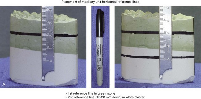
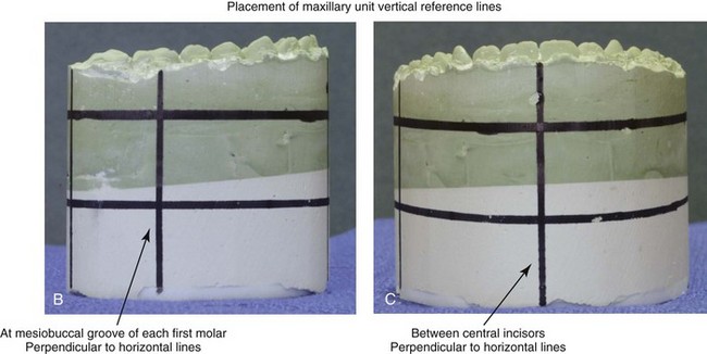
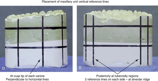
Figure 13-5 Marking horizontal and vertical reference lines on the articulated dental casts. A, The maxillary unit horizontal reference lines are placed parallel to the base plate. The first horizontal reference line is placed entirely in the green stone. The second is placed entirely in the white plaster, with 15 mm to 20 mm of separation between the lines. B, A maxillary unit vertical reference line is placed at the mesiobuccal groove at each first molar, perpendicular to the horizontal lines. C, The next maxillary unit vertical reference line is placed between central incisors, perpendicular to the horizontal lines. D, Additional maxillary unit vertical reference lines are placed at the cusp tip of each canine, perpendicular to the horizontal lines. E, Vertical maxillary unit reference lines are also placed posteriorly in the tuberosity regions. Two reference lines are generally placed on each side, adjacent to the alveolar ridges. Similar horizontal and vertical reference lines are placed on the mandibular unit.
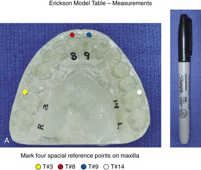
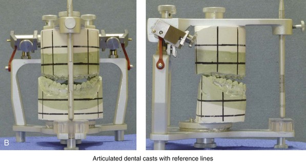
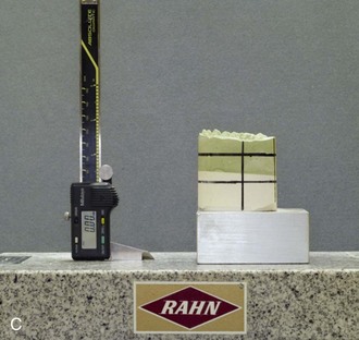
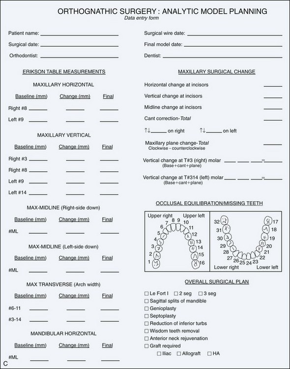
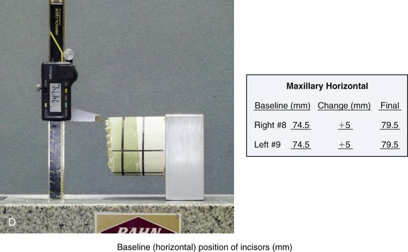
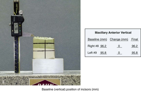
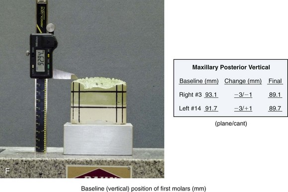
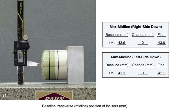
Figure 13-6 The Erickson Model Table (EMT) is used to register the baseline maxillary orientation in all three planes in space. The baseline measurements are then used to assist with the accurate repositioning and reorienting of the maxilla in accordance with clinical requirements. A, With a Sharpie marking pen, a reference dot is placed at the mesiobuccal cusp tip of each maxillary first molar and the midpoint of each maxillary central incisor. B, The articulated dental casts with horizontal and vertical reference lines already marked are now ready for baseline maxillary reference measurements taken from the EMT. C, The maxillary unit is attached to the EMT base mount from which measurements will be made. C, The standard orthognathic surgery model-planning data sheet is shown. D, The EMT is used to measure the baseline horizontal position of the incisors in millimeters. This is the distance between the base of the EMT and the incisal edge of each maxillary central. The millimeter number is recorded on the data sheet. The desired horizontal surgical change at the maxillary incisors is also written on the data sheet. The final preferred horizontal position of the maxillary incisors, as a result of model planning, is calculated and recorded. E, The EMT is used to measure the baseline vertical position of the incisors in millimeters. This is the distance between the base of the EMT and the incisal edge of each maxillary central incisor. The millimeter number is recorded on the data sheet. The desired vertical surgical change at the maxillary incisors is also written on the data sheet. The final preferred vertical position of the maxillary incisors, as a result of model planning, is calculated and recorded. F, The EMT is used to measure the baseline vertical position of each maxillary first molar. This is the distance between the base of the EMT and the mesiobuccal cusp tip of each maxillary first molar. The millimeter number is recorded on the data sheet. The desired vertical surgical change at each maxillary first molar is also written on the data sheet. The final preferred vertical position of the maxillary molars, as a result of model planning, is calculated and recorded. G, The EMT is used to measure the baseline transverse midline position of each incisor in millimeters. This is an indication of the maxillary dental midline position from both the right side down and left side down directions. The base measurement is recorded on the data sheet. The desired transverse change at the maxillary incisor is written on the data sheet. The final preferred transverse midline position of the maxillary incisor, as a result of model planning, is calculated and recorded.
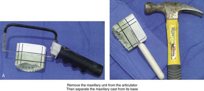
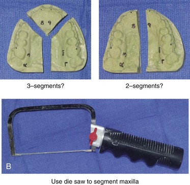
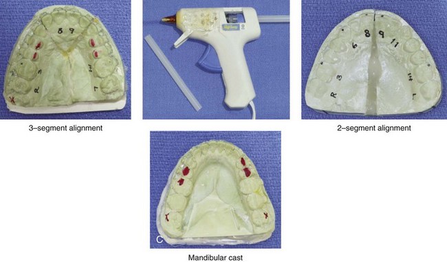
Figure 13-7 The maxillary unit is now removed from the articulator. A, The maxillary cast is separated from its base. This is accomplished with the use of a die saw to cut a groove and a knife that is placed into the groove, which is then hit with a hammer. B, If indicated, segmentation of the maxillary cast is carried out. This is done in accordance with patient-specific needs to correct the maxillary arch form. Segmentation is generally carried out either as two parts (i.e., between the central incisors and then through the hard palate) or as three parts (i.e., between the lateral incisor and the canine on each side and then through the hard palate). The maxilla is cut by hand with a die saw instrument. C, If segmentation of the maxillary cast is required, the cut segments are placed into the corrected arch form by aligning the segments over the mandibular arch. It is important to maintain a physiologic orientation of the interdental papilla, with tight contact between the teeth. Ideally, the adjacent roots are also parallel, with minimal divergence. The maxillary segments are secured together in the corrected arch form with the use of hot glue from a glue gun.
 NOTE: If occlusal equilibration is required to achieve the preferred articulation, it is completed on the casts and recorded at this time. The actual occlusal equilibration procedure is completed during surgery.
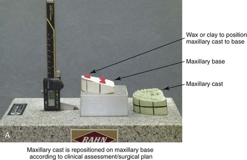
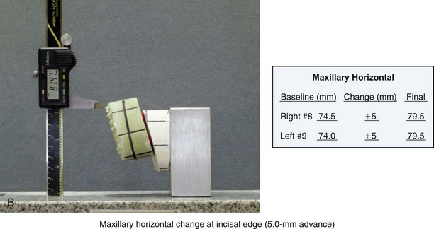
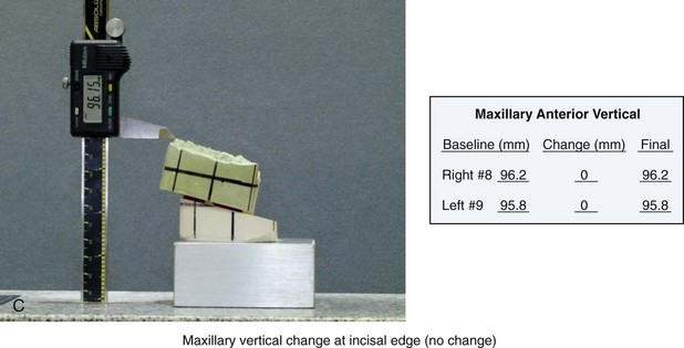
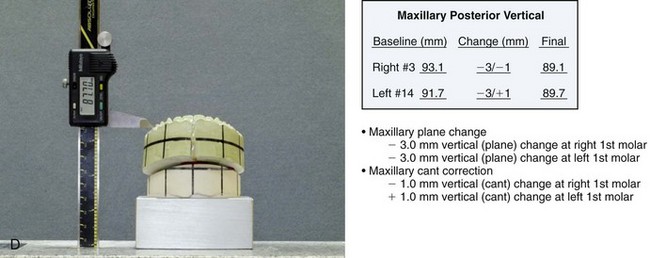
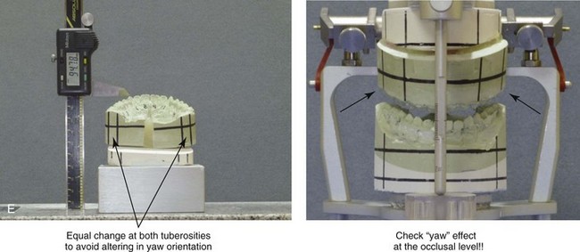
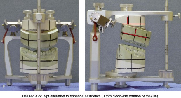
Figure 13-8 A, The maxillary cast is next repositioned and reoriented on the maxillary base in accordance with the clinical assessment and the surgical plan. The Erickson Model Table (EMT) is used to ensure the correct spatial reorientation of the maxillary cast to achieve the clinical objectives. B, The EMT is used to accurately reposition the maxilla. For this patient (see Fig. 13-1), the maxillary horizontal change at the incisal edge is a 5-mm advancement. C, In this case, the EMT also confirms that no vertical change will occur at the maxillary incisal edge. D, The EMT is used to accurately reposition the maxilla at the molars. The confirmation of correct positioning at the mesiobuccal cusp tip of each first molar is essential. The vertical change incorporates the desired three-dimensional roll and pitch changes. E, When repositioning the maxilla, the EMT is useful to check for any yaw effect. Establishing equal side-to-side changes at both tuberosity regions is required to avoid a yaw change of the posterior maxilla. The reoriented maxillary unit is placed back onto the articulator for viewing. F, The vertical pin on the articulator should remain neutral throughout the process.
 NOTE: Before going forward with intermediate splint construction, confirming the yaw orientation of the maxilla relative to the mandible is essential.
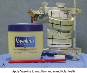
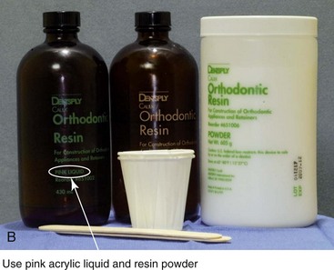
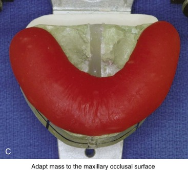
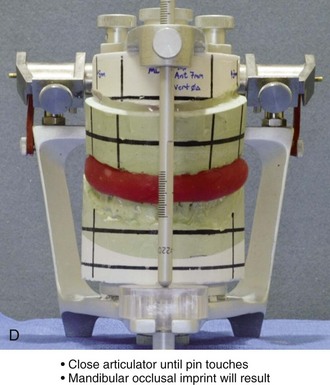
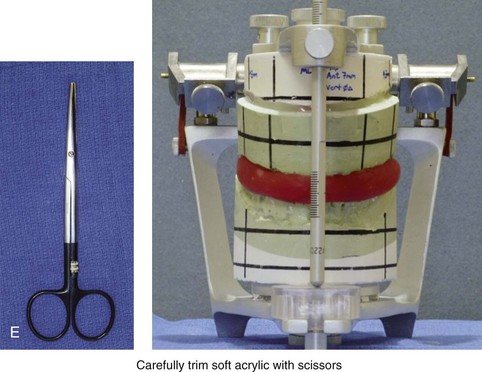
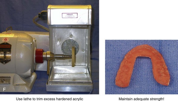
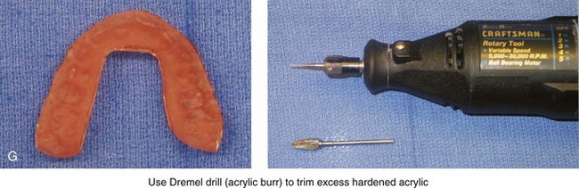
Figure 13-9 Construction of the intermediate splint. A, Apply a thin coat of Vaseline to the maxillary and mandibular teeth. B, Use pink acrylic liquid and orthodontic resin powder, and mix them until the mass does not slump. C, Roll the mixed acrylic mass into a log shape. Adapt the mass to the maxillary occlusal surface. D, Close the articulator until the vertical pin touches in a neutral location. A mandibular occlusal surface imprint will result. E, Limit “undercuts” from brackets by carefully trimming the soft acrylic with scissors. F, When the acrylic is dry, use a lathe to trim excess hardened acrylic. Maintain adequate strength of the splint to prevent bowing or breakage during surgery. G, Use a rotary drill (e.g., a Dremel drill) with an acrylic bur to further trim excess hardened acrylic.
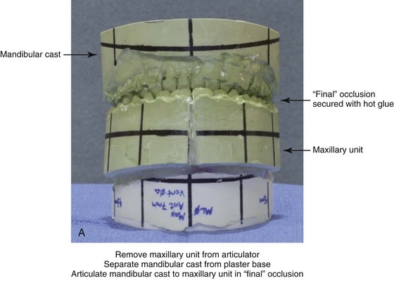
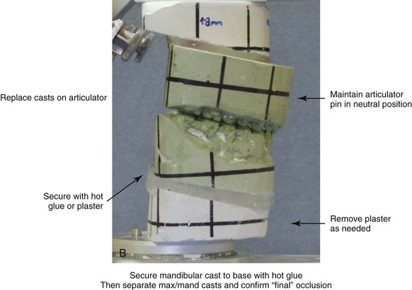
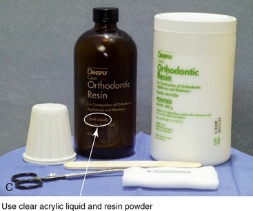
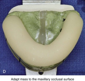
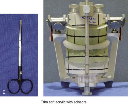
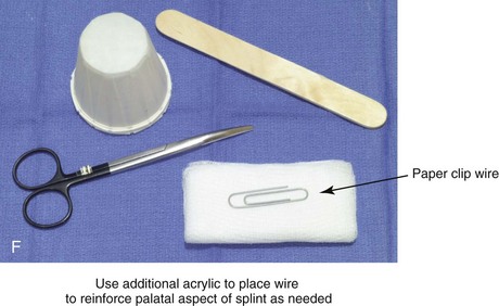
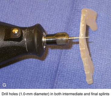
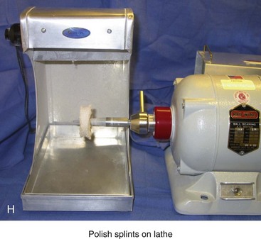
Figure 13-10 Construction of the final splint. A, Remove the maxillary unit from the articulator. Separate the mandibular cast from the plaster base as previously described for the maxillary unit (see Fig. 13-7, A). Next, articulate the mandibular cast with maxillary unit in the final desired occlusion. Secure the final occlusion with hot glue from a glue gun. B, Secure the mandibular cast back to the base with the use of either hot glue from a glue gun or white plaster. Maintain the articular pin in a neutral position to achieve this objective. It is generally necessary to remove as least some plaster from the mandibular base during this process; only then is the hot glue or additional plaster used to secure the mandibular cast back to the base. The dried glue that secured the occlusion together is now released. The desired occlusion is confirmed to be accurate before the construction of the final splint. C, Use clear acrylic liquid and orthodontic resin powder for the final splint. Mix the two together until the mass does not slump. D, Roll the mixed acrylic mass into a log shape. Adapt the mass to the maxillary occlusal surface. E, Close the articulator until the vertical pin touches in a neutral position. The mandibular occlusal surface will imprint into the acrylic as a result. Limit “undercuts” from the brackets by carefully trimming the soft acrylic with scissors. F, Use additional acrylic to place a metal wire, if needed, to reinforce the palatal aspect of splint. This will prevent bowing or breakage of splint when segmental osteotomies are carried out and when extensive arch expansion is required. G, Use a lathe and a rotary drill (e.g., a Dremel drill) to trim excess acrylic from the hardened final splint. Next, place each splint (i.e., intermediate and final) in turn on the maxillary cast, and determine the best location and direction for each interdental drill hole. Complete 1-mm drill holes with the use of a rotary drill (e.g., a Dremel). H, Polish the splints on a lathe with the use of a cloth buffing wheel (i.e., pumice and Acrilustre) (Robert Bosch, 1800 W. Central Road, Mt. Prospect, IL).
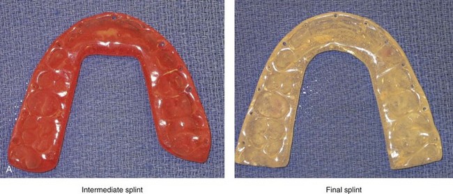
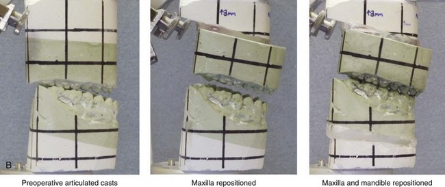
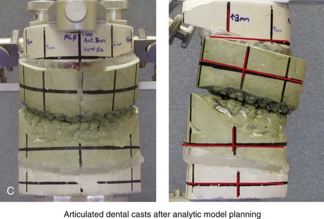
Figure 13-11 Dental casts on the semi-adjustable articulator to demonstrate model planning and a view of the finished splints. A, Intermediate and final splints finished and ready for use. B, Lateral views of articulated dental casts first mounted in a centric relation bite and then after maxillary and final mandibular repositioning. C, Frontal and side views of articulated dental casts demonstrating model planning. In this case, note the extent of the maxillary clockwise rotation (3 mm) needed to achieve a preferred A-point to B-point relationship and also to overcome the procumbency of the maxillary incisors.
Although clinical decision making regarding the preferred aesthetic reorientation and repositioning of the jaws in the operating room remains both an art and a science (see Chapter 12), the technical aspects of planning should be precise and consistent. Analytic model planning and the use of prefabricated splints continue to represent the standard of care for bimaxillary and segmental maxillary osteotomies.8,9,15,16,22,26,44,55,77,78,80,85,86
Despite the benefits of this time-honored approach, there is the potential to introduce error. For example, during bimaxillary surgery, if an inaccurate bite registration is obtained from the patient preoperatively in the clinic setting, this will be transferred to the articulated models; this leads to inaccurate splint construction and then to intraoperative errors when the splints are relied on during surgery. The surgeon’s ability to obtain an accurate and reproducible bite registration in CR during the immediate presurgical clinical examination, is one of the essential steps to avoid unintended errors.10,28–35,42,43,49,58,60,64,65,71–76,82
Controversies Surrounding Model Planning for Orthognathic Surgery
Articulator and Face-Bow Device Options
For orthognathic surgery, analytic model planning typically involves the use of an articulator that provides an approximation of the anatomic relationship between the hinged axis and the incisors. This type of articulator mechanism is designed to approximate the individual’s actual mandibular autorotation. This is especially important for bimaxillary surgery, when autorotation of the maxillomandibular complex helps to dictate the position of the maxilla before the mandibular osteotomies are completed. Marko conducted research to demonstrate that the mathematical difference in the horizontal projection achieved when such advancement is carried out in combination with a maxillary impaction of 5 mm is significantly affected by the type of articulator that is used.46 An average error of 2 mm was found with use of the Galetti articulator (simple hinge), whereas only 0.2 mm of error occurred with the Hanau articulator (semi-adjustable).46
 NOTE: The use of a semi-adjustable articulator in bimaxillary surgery will be more accurate and is therefore preferred to the use of a simple hinge articulator.
O’Malley and Milosevic compared three face-bow semi-adjustable articulator systems to measure any differences in the recorded steepness of the occlusal plane that was produced.52 The three articulators studied were the Dentatus type ARL; the Denar MkII; and the Whip Mix Quickmount 8800. The recorded measurement of the steepness of the occlusal plane was taken as the angle between the face-bow bite fork and the horizontal arm of the articulator. This measurement was then compared with the angle of the maxillary occlusal plane to the Frankfort plane as measured via lateral cephalometry. Of the three semi-adjustable articulators tested, the Whip Mix Quickmount 8800 came closest to achieving the maxillary occlusal plane (with respect to the Frankfort plane) as measured via lateral cephalometry; it flattened the occlusal plane by only 2 degrees (P < .05). The results of the Dentatus and Denar MkII articulators demonstrated flattening of the occlusal plane by 5 degrees and 6.5 degrees, respectively. Ellis also demonstrated how commonly used methods of face-bow registration may erroneously capture the spatial relationship of the maxilla with the Frankfort horizontal plane.18 This is likely to be problematic if the surgeon intends to use the Frankfort horizontal from the patient’s cephalogram as the reference plane from which facial aesthetic objectives will be planned.
Stay updated, free dental videos. Join our Telegram channel
VIDEdental - Online dental courses


