CHAPTER 11 Surveying
For a removable prosthesis, the necessity for appropriately planned and executed tooth preparation, followed by verification of a well-fitting prosthesis that engages the teeth as planned, is equally important. As was briefly mentioned in Chapter 7, a dental surveyor is vitally important to the planning, execution, and verification of appropriate mouth modifications for a removable partial denture. Although it does not necessarily affect the occlusal rest preparations on abutment teeth, use of the surveyor is critical for planning the modifications of all tooth surfaces that will be involved in support, stabilization, and retention of the prosthesis. In this role, the use of a surveyor to determine the needed mouth preparation is vitally important in helping to provide stable and comfortable removable prostheses.
Description of Dental Surveyor
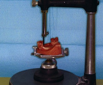
The most widely used surveyors are the Ney (Figure 11-1) and the Jelenko (Figure 11-2). Both of these are precision-made instruments. They differ principally in that the Jelenko arm swivels, whereas the Ney arm is fixed. The technique for surveying and trimming blockout is therefore somewhat different. Other surveyors also differ in this respect, and the dentist may prefer one over another for this reason.
The principal parts of the Ney surveyor are as follows:
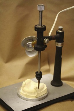
Because the shaft on the Ney surveyor is stable in any vertical position—yet may be moved vertically with ease—it lends itself well for use as a drill press when a handpiece holder is added (Figure 11-4). The handpiece may thus be used to cut recesses in cast restorations with precision with burs or carborundum points of various sizes in a dental handpiece.
Purposes of the Surveyor
Surveying the Diagnostic Cast
Contouring Wax Patterns
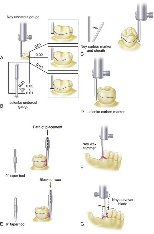
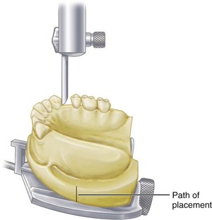
The surveyor blade is used as a wax carver during this phase of mouth preparation, so that the proposed path of placement may be maintained throughout the preparation of cast restorations for abutment teeth (Figure 11-7).
Surveying Ceramic Veneer Crowns
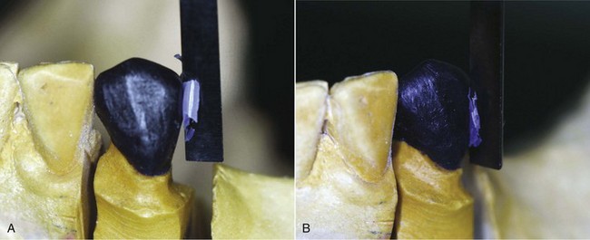
Ceramic veneer crowns are often used to restore abutment teeth on which extracoronal direct retainers will be placed. The surveyor is used to contour all areas of the wax pattern for the veneer crown except the buccal or labial surface. It must be remembered that one of the principal goals in using a porcelain veneer restoration is to develop an esthetic replica of a natural tooth. It is unlikely that the ceramic veneer portion can be fabricated exactly to the form required for the planned placement of retentive clasp arms without some reshaping with stones. Before the final glaze is accomplished, the abutment crowns should be returned to the surveyor on a full arch cast to ensure the correct contour of the veneered portions or to locate those areas that need recontouring (Figure 11-8). The final glaze is accomplished only after the crowns have been recontoured.
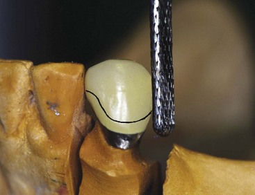
Figure 11-8 Resultant metal-ceramic surveyed crown from Figure 11-7, which is being refined to maintain the distal guide plane and buccal height of the contour previously designed. Final glaze has not been placed on the veneer crown and required alterations of surfaces to conform to ideal placement of the retainer (solid line) can be performed by machining. Final glaze is produced only after necessary recontouring is accomplished.
Placement of Intracoronal Retainers (Internal Attachments)
In the placement of intracoronal retainers, the surveyor is used as follows:
Placement of Internal Rest Seats
An internal rest differs from an internal attachment in that some portion of the prosthesis framework is waxed and cast to fit into the rest seat rather than a matched key and keyway attachment used (see Figures 6-13 and 6-14). The former is usually nonretentive but provides a definite seat for a removable partial denture or a cantilever rest for a broken-stress fixed partial denture. When they are used with fixed partial dentures, nonparallel abutment pieces may be placed separately.
The internal rest in partial denture construction provides a positive occlusal support that is more favorably located in relation to the rotational axis of the abutment tooth than the conventional spoon-shaped occlusal rest. It also provides horizontal stabilization through the parallelism of the vertical walls, thereby serving the same purpose as stabilizing and reciprocal arms placed extracoronally. Because of the movement of a distal extension base, more torque may be applied to the abutment tooth by an interlocking type of rest, and for this reason its use in conjunction with a distal extension partial denture is considered to be contraindicated. The ball-and-socket, spoon-shaped occlusal, or noninterlocking, rest should be used in distal extension partial denture designs. Use of the dovetailed or interlocking internal rest should be limited to tooth-supported removable restorations, except when it is used in conjunction with some kind of stress-breaker between the abutments and the movable base. The use of stress-breakers has been discussed in Chapter 9.
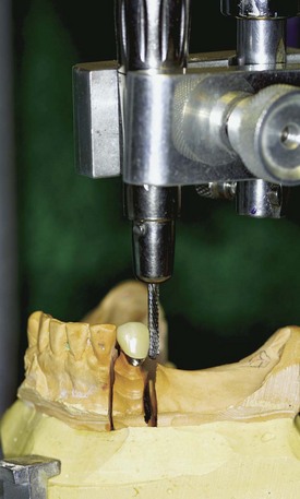
Machining Cast Restorations
With a handpiece holder attached (see Figure 11-4), the axial surfaces of cast and ceramic restorations may be refined by machining with a suitable cylindrical carborundum point. Proximal surfaces of crowns and inlays, which will serve as guiding planes, and vertical surfaces above crown ledges may be improved by machining, but only if the relationship of one crown to another is correct (see Figure 14-9). Unless the seating of removable dies is accurate and they are held in place with additional stone or plaster, cast restorations should first be tried in the mouth and then transferred, by means of a plaster or acrylic-resin index impression, to a reinforced stone cast for machining purposes. The new cast is then positioned on the surveyor, conforming to the path of placement of the partial denture, and vertical surfaces are machined with a true-running cylindrical carborundum point.
Surveying the Master Cast

Stay updated, free dental videos. Join our Telegram channel
VIDEdental - Online dental courses


