11
Endodontic Techniques
Technically, endodontic treatment of teeth comprises three major phases that may be of equal importance for the outcome of the treatment. The three phases are:
— preparation for treatment,
— root canal instrumentation,
— root canal obturation.
In the last decade it has become common practice to use an operating microscope during the various phases of endodontic treatment. (Fig. 11.1). The microscope offers magnification, but almost as important, it gives excellent light directly through the lenses into the access cavity. This gives the operator tremendous advantages, especially in difficult cases, and in straight root canals it is possible to observe the canal all the way to the apical foramen.
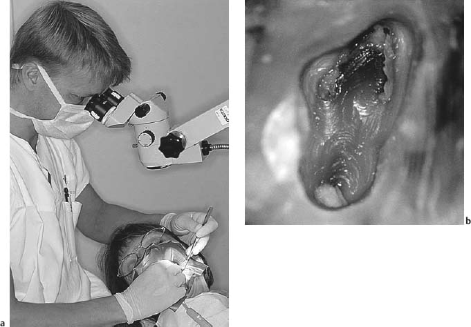
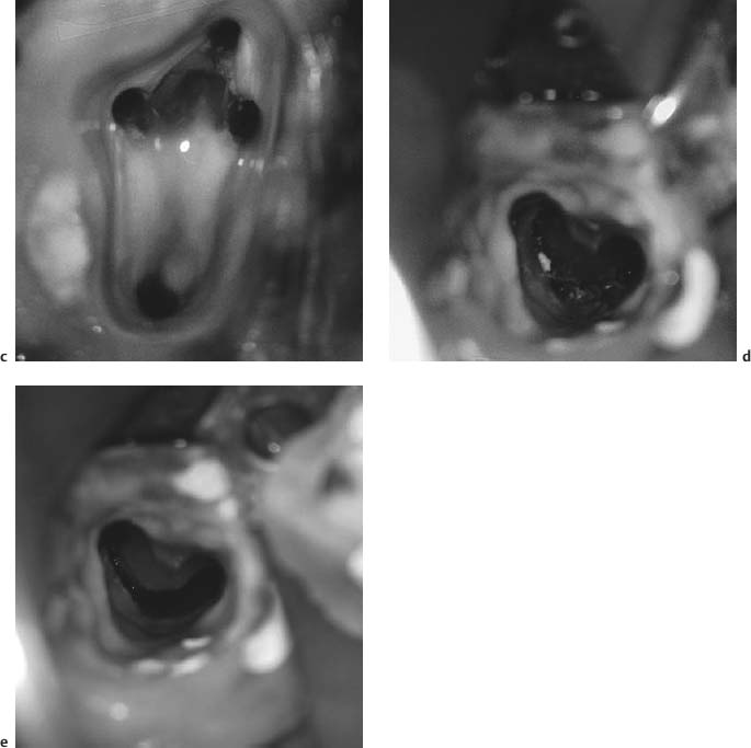
Fig. 11.1
a Operating microscope in use during root canal instrumentation.
b Pulp chamber floor of maxillary molar photographed through the microscope. A certain magnification and the direct light into the access cavity make it easier to locate and instrument the canals.
c Four canals instrumented.
d Pulp chamber floor of tooth with apparent irregular root canal anatomy.
e During instrumentation it became evident that the tooth had a C-shaped canal that was effectively prepared with relative ease using the microscope.
Preparation for Treatment
Preparation for treatment entails the establishment of the root canal to be treated in an aseptic field of operation. It consists of the preparation of an adequate access cavity, the secure placement of a rubber dam, and disinfection of the rubber dam, the tooth, and the pulp chamber.
Access Cavity
The objective of the access cavity is to provide as unobstructed an access to the root canal(s) of the tooth as possible. When mishaps occur during the instrumentation and obturation phases of the treatment, they can most frequently be attributed to an inadequately or incorrectly prepared access cavity. The most common mistake is an access opening that has been made too small. As a result, canals are missed or the manipulation of the root canal instruments is unnecessarily hindered by the cavity walls. Also, tissue may be left behind in the coronal pulp, especially in the pulp horns, leading to discoloration of the tooth. On the other hand, tooth structure should not be removed indiscriminately since that would lead to an unnecessary weakening of the tooth and would complicate the restorative procedures. The access cavity should expose the entire pulp chamber, including the pulp horns. In addition, cusps may have to be reduced to provide proper access to certain canals or to prevent uncontrolled fractures if they are weak.
Before the preparation of the access cavity begins, a good radiograph of the crown of the tooth, taken with a long-cone paralleling technique, is studied (Fig. 11.2). Especially the distance from an occlusal or incisal point of reference to the roof of the pulp chamber is noted. This distance may be marked on the bur to be used for the penetration of the crown to the pulp. Carious dentin is always removed, and fillings and restorations which might prevent a direct view to the root canals are removed as well. Also, all undermined cusps are reduced at this time in order to prevent crown-root fractures which might jeopardize the treatment of the tooth.
For the actual penetration to the pulp chamber, a long-shank round carbide bur is used in a low-torque ultraspeed handpiece. A long-shank bur is not necessarily used because of the distance to be penetrated, but more because it allows for better visibility and a better possibility of angling the bur correctly in relation to the long axis of the tooth. Porcelain crowns are penetrated by standard-length, round, diamond-coated burs and the access cavity is then finished with the long-shank carbide bur. When the penetration to the pulp has been achieved, the roof of the pulp chamber is removed by pulling strokes with the bur from the chamber in an occlusal or incisal direction (Fig. 11.3). In this way the entire pulp chamber is exposed without overhangs of occlusal tooth substance and without danger of perforations laterally or in the furcation region. The coronal pulp tissue, vital or necrotic, is then removed. A round bur no. 2 may be used with advantage to ensure complete removal of tissue in the pulp horn areas of incisor teeth.
A double-ended endodontic explorer (DG-16) which offers two angles of probing is then used to locate the orifices of the root canals on the floor of the pulp chamber. The use of the explorer will also indicate whether the access cavity is adequate or whether, as is often the case, a cavity wall has to be flared more or a cusp be cut to improve the access to the canals. Often it will be evident clinically and radiographically that a root canal is calcified in the orifice area. The microscope is then extremely useful. Sometimes a rigid explorer may be used to penetrate the calcified material. Other times a long-shank bur is used to remove hard tissue to expose the canal. Since the exact location of the root canal is not always known, the bur is used with careful shaving motions in the orifice area. The explorer is used at frequent intervals in an effort to break through the calcified tissue. Exact placement of a 37% phosphoric acid gel for 60 seconds on the calcified orifice may be helpful as well. The access cavity preparation is complete when the root canals have been located and are accessible for treatment.
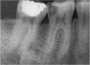
Fig. 11.2 Radiograph of mandibular teeth. The distance between the occlusal surface and the roof of the pulp chamber should be determined prior to the preparation of an endodontic access cavity.
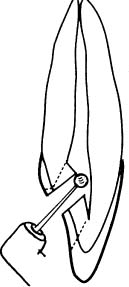
Fig. 11.3 Diagram illustrating penetration of the pulp chamber with a bur. The roof of the pulp chamber is then carefully removed with outward pulling strokes of the bur.
The access cavity is prepared prior to the application of a rubber dam to ensure maximal visibility of the teeth and the relationship between their crowns and roots. This will prevent root perforations and is especially important during the location of the root canal orifices. However, all subsequent treatment is carried out aseptically with the use of a rubber dam.
Rubber Dam
A rubber dam is placed on a tooth to be treated endodontically mainly for three reasons:
1) to obtain a field of operation that can be disinfected,
2) to protect the patient from accidentally aspirating or swallowing a root canal instrument, and
3) to protect the patient from the effect of irrigating solutions and other drugs during the treatment.
In addition, there are other advantages with the use of a rubber dam. It makes the treatment faster and, in many ways, less difficult in that it physically eliminates any interference from the oral environment.
Normally, only the tooth to be treated is exposed through a hole in the rubber dam (Fig. 11.4). A medium-weight dam will give a good seal around the tooth, usually without the use of a dental floss ligature. A wide variety of clamps are available to hold the rubber dam in place (Fig. 11.5), and the use of clamps with wings allows a rapid application of the rubber dam. A rubber dam frame of a radiolucent material that can be left in place during the taking of radiographs should be used (Fig. 11.4). The frame should also make it possible to cover the nose of the patient to prevent contamination of the field of operation by nasal microorganisms.
If the tooth to be treated is severely broken down, it may be practical to restore it temporarily before the root canal treatment begins. This is also done to strengthen the tooth, but mainly to facilitate the placement of a well-sealing rubber dam. A quick and adequate method, if enough retention is available, is to restore the tooth with a resin after acid-etching the remaining tooth structure (Fig. 11.6). In such instances the pulp chamber may be filled with tightly packed cotton pellets to prevent the resin from blocking the root canal orifices and to facilitate an easy recapitulation of the access cavity. In severely broken-down molar teeth, an orthodontic band may be useful to ensure asepsis. The band must fit snugly at the cemental–enamel junction and should be about 2 mm high to allow an adequate hold for the rubber dam clamp and easy access to the root canals. The floor of the chamber is again packed with hard cotton pellets and the band is filled with zinc oxiphosphate cement and cemented to the tooth. When the cement has set, the cotton pellets are removed, the access cavity is recapitulated, and the preparation is redefined as needed. If the tooth is fractured at the gingiva, a slight gingivectomy, preferably using electrosurgical instruments to prevent bleeding, may make it possible to apply an adequate rubber dam. In such instances it is also possible to apply the rubber dam to teeth adjacent to the one to be treated (Fig. 11.7).
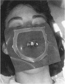
Fig. 11.4 Rubber dam applied to a maxillary central incisor for endodontic treatment. Only the tooth to be treated is exposed and the rubber dam is held in place by a clamp placed on this tooth and the use of a rubber dam frame. Note that the patients’s nose is covered by the rubber dam. This is imperative in order to maintain a bacteria-free field of operation. (The frame is outside the rubber dam for demonstration purposes only.).
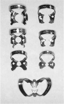
Fig. 11.5 Example of rubber dam clamps. A wide variety of clamps are available for most clinical situations.
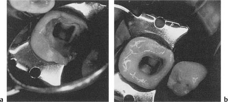
Fig. 11.6
a Deep mesial cavity making it difficult to obtain effective isolation of the tooth with a rubber dam.
b Cavity is acid-etched, and a mesial wall is fabricated by means of light-cured resin. A dry field of operation is now readily obtained.
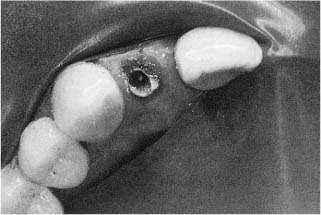
Fig. 11.7 Endodontic treatment of a severely broken down maxillary lateral incisor. The rubber dam is attached to neighboring teeth and although not ideal, protects the patient and helps establish a dry, clean field of operation. However, great care must be taken during the use of root canal irrigants and other medicaments in such situations.
Special considerations in the preparation of access cavities in the various groups of teeth are discussed in Chapter 12.
When the rubber dam has been applied and the tooth to be treated is effectively sealed from the oral environment, an aseptic field of operation is established. The access cavity, the tooth, and the rubber dam are disinfected by effective surface-active agents, usually chlorhexidine or iodine preparations combined with hydrogen peroxide or ethanol.
Root Canal Instrumentation
At this time, the instruments used for the preparation of the access cavity and the application of the rubber dam are removed, and a tray with sterile instruments to be used for the root canal instrumentation is made available (Fig. 11.8).
Length determination. Regardless of technique used, step-back or crown down, hand instruments or motorized instruments, before the actual instrumentation begins the length of the root canal is determined. A small K-file, most often no.15, is introduced into the canal to a level near the apex of the root and a radiograph is taken (Fig. 11.9). The apical level of instrumentation is determined based on the location of the tip of the file in relation to the apex of the root as seen in the radio-graph. The length of instrumentation from an occlusal or incisal point of reference, i. e., the working length, is then calculated. Please note that it is the apex of the root that most often serves as the radiographic landmark and not the apical foramen or apical constriction. The reason for this is that the apex of the root is almost always distinguishable in a radiograph, whereas the foramen rarely is. Obviously, in the few instances when the apical foramen is actually seen radiographically, it should be used to determine the working length.
Electronic devices are available to determine the location of the apical foramen of teeth. The use of these so-called electronic apex locators is based on the hypothesis that the electrical resistance between the periodontal ligament and the oral mucosa is virtually constant. The instrument is calibrated by measuring the resistance between the gingival crevice and the lip. An endodontic instrument attached to the crevice electrode is then inserted into the root canal until the same electrical resistance is registered. It is then assumed that the tip of the instrument has reached the periodontal ligament at the apical foramen.
With clinical practice the electronic apex locator may become a valuable aid in routine endodontics, but even more so in special clinical situations when the radiographic image of the root apices is unclear, when there is suspicion of a root perforation or root fracture, when radiographs are contraindicated, etc. In addition, the instrument offers an excellent opportunity for quick and, if needed, frequent checks on whether the correct working length is actually maintained during the instrumentation phase of the treatment. The electronic apex locator has a definite place in modern endodontic therapy.
Extirpation of the pulp. When the working length has been established, the pulp of vital teeth is removed. A K-type instrument with as large a diameter as possible is introduced into the canal to the predetermined apical level of instrumentation. The instrument is then rotated as much as possible in contact with the root canal wall in an effort to sever the pulp at this level. If this is successful, the pulp may come out in one piece and a pulp stump with a clean-cut wound is left behind in the root canal (Fig. 11.10). If it is not successful, the pulp tissue will instead be removed in bits and pieces during the subsequent instrumentation of the canal.
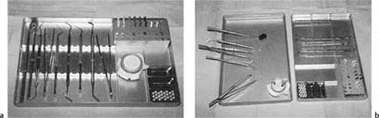
Fig. 11.8
a Practical endodontic tray. It contains hand instruments needed during the aseptic phase of the treatment as well as a holder with root canal instruments. The hand instruments: mirror, explorer, pair of pliers, endodontic explorer (DG16), periodontal probe, root canal spreader (D11), spoon excavator (31 L), plastic instrument (Glick no. 1), curved, heavy anatomical pliers. The root canal instruments: K-files (size 15–80), Hedstrom files (size 15, 20, 30, 40, and 50), finger spreaders (size B and D).
b The lid of the tray is used as a work surface. The tray itself should remain sterile throughout the treatment. The anatomical pliers are used to move instruments from the tray to the lid.
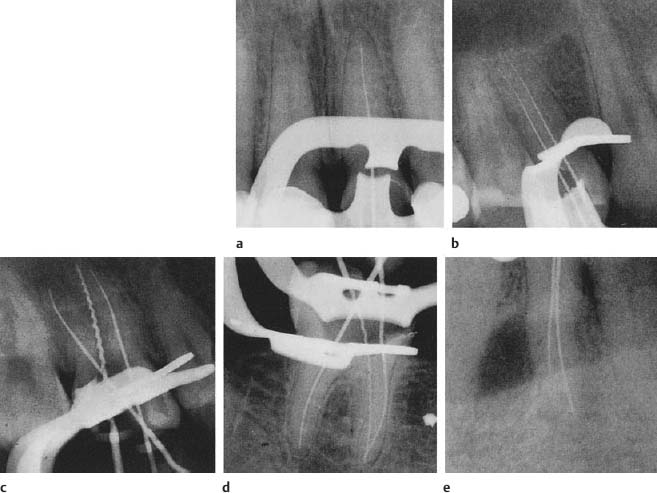
Fig. 11.9 a–e Radiograph to determine the tooth length of various types of teeth. In multirooted teeth and especially in roots with more than one canal it is advantageous to use different types of root canal instruments to readily determine which canal is which. In these radiographs, Hedstrom files are consistently used in palatal and lingual canals and K-files in buccal canals. Roots with more than one canal must be exposed at an angle (usually about 15°) to separate the canals in the radiographs.
In nonvital teeth with ischemic necrosis, the pulp may be extirpated using the same method. However, in teeth with liquefaction necrosis of the pulp, there is usually so little tissue left in the root canal that an extirpation as such is not feasible. Rather, the tissue remnants will be removed during chemomechanical instrumentation.
Chemomechanical instrumentation. The principles and goals of the instrumentation phase of endodontic treatment are the same regardless of instruments or technique used (see Chapters 5 and 6). However, the actual preparation of the canal may vary, depending on, among other things, the preferred obturation technique.
Step-Back Preparation
With the step-back technique, the diameter of the root canal at the apical level of instrumentation is kept as small as possible to resist extrusion of filling material beyond the canal. In addition, the apical part of the canal is given a moderately tapered form in an attempt to retain the obturating materials within the canal. Further coronally, the canal is flared as much as necessary according to the anatomy of the canal and to facilitate the obturation of the canal. The flare of the canal is especially pronounced with the use of thermoplasticized gutta-percha obturation techniques which require the insertion of rather large and rigid instruments to the apical region of the canal (see p.191).
The degree of instrumentation most apically in the root canal is determined by the size of the first K-file that binds in the canal at the apical level of instrumentation. The canal is then enlarged an additional two instrument sizes at this level. This means that if a no.15 file binds, the canal is enlarged to a size 25. The last file used most apically, in this instance no. 25, is called the master apical file. The apical taper is then accomplished by a step-back use of instruments of increasing sizes (Fig. 11.11). Between each change of file, the full length of the canal is recapitulated with the master apical file. Further coronally, the canal is then flared with hand or engine-driven instruments to give it the desired continuous tapered shape.
The step-back technique can be used in all teeth. However, if the root canal is wide apically so that little natural resistance is offered, a more definite shelf may have to be prepared in the canal wall to help prevent overfilling during the obturation phase. Also, when the step-back technique is used, it must be remembered that the root canal in many teeth is considerably wider in a buccolingual than in a mesiodistal direction. The first instrument that binds will do so in the narrowest part of the canal, and an enlargement of two to three instrument sizes, which most often will mean 0.10–0.15 mm, may not be enough to reach the walls at the widest part of the canal. Thus, tissue commonly is left behind apically with the step-back technique, especially on the lingual aspect of the root canal wall (Fig. 11.12).
Apical Box Preparation
An important result of morphometric studies of the root canals of human teeth is that apically the canals may be wider than assumed and should be enlarged more than has commonly been done—in some groups of teeth, like the incisors, considerably more (see Chapter 12). The apical box preparation technique was developed with this information in mind. With this technique, one attempts to give the apical 2–5 mm of the root canal a cylindrical shape rather than the tapered shape of the step-back technique (Fig. 11.13). In this way it is hoped one can obtain clean walls consistently in the important apical part of the root canal. K-type instruments are used with filing and rotary cutting actions, stainless steel files sizes 08–20, and nickel-titanium files sizes 25 and up. Further coronally, the canal is flared to a continuous taper with Hedstrom files or engine-driven instruments as with the step-back technique.
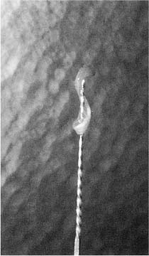
Fig. 11.10 Pulpectomy. The pulp has been severed in the apical area of the root canal by means of a reamer and is removed in one piece.
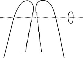
Fig. 11.11 Diagram illustrating the step-back preparation of a root canal. A moderately tapered form of the apical end of the root canal is obtained by a step-back use of instruments of increasing size. No attempt is made to obtain a circular shape of the canal, which usually remains wider in a buccolingual direction than in a mesiodistal direction.
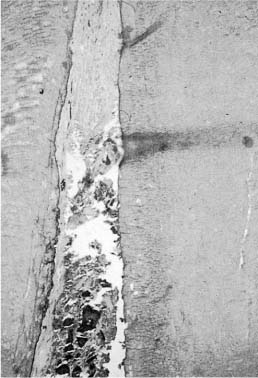
Fig. 11.12 Buccolingual longitudinal section of the apical area of the root canal of a pulpectomized tooth instrumented with the step-back technique. The pulp has been nicely severed, but since the root canal is wider buccolingually than mesiodistally, the buccal and lingual walls are not well instrumented and pulp tissue is left behind on the lingual wall (hematoxylin-eosin).
The apical part of the root canal is opened up with a K-file used with filing motions until the file moves freely in the canal. The file is then rotated with its tip at the exact working length to begin making a shelf in the root canal wall. The next size file is introduced into the canal with twiddling motions until the tip is again at the exact apical level of instrumentation. The instrument is then carefully rotated or, if necessary, used with filing strokes first until it can safely be rotated at the desired apical level. The preparation of the apical part of the canal continues systematically with filing and reaming actions until the canal is enlarged two to three instrument sizes. The canal is then flared, beginning with a Hedstrom or engine-driven file one size smaller than the last instrument used apically. The patency of the apical part of the canal is checked at regular intervals during the flaring of the coronal part of the canal.
When the flare is considered adequate, the preparation of the apical part of the canal is completed with K-type hand or engine-driven instruments, again mainly with rotary cutting actions. In this way, a shelf is prepared in the root canal wall at the apical-most level of instrumentation (Fig. 11.13). However, due to the noncutting tip of modern root canal instruments, the apical shelf will not be abrupt, but rather have a sloping form (Fig. 6.11). Still, the shelf constitutes an effective apical stop against which a master gutta-percha point of the same size as the final apical instrument can be seated. Also, since the final apical instrumentation is carried out with rotary cutting actions, the apical part of the root canal will, if at all possible, have taken on the shape of a cylindrical box.
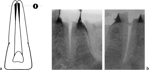
Fig. 11.13
a Diagram illustrating differences in the shape of an apical root canal after step-back and apical box preparation. With the apical box preparation technique, an attempt is made to give the apical root canal a circular shape.
b Radiographs showing (left) a mandibular premolar with step-back preparation and (right) the contralateral tooth with apical box preparation of the root (final reamer no. 70). Note that the two methods differ only in the preparation of the apical part of the canal. The enlargement and flare of the canals further coronally are similar.
The degree of apical enlargement is determined by the size, shape, and form of the root of the tooth as seen in preoperative radiographs. However, since root canals often are widest in the buccolingual direction, which normally cannot be evaluated in radiographs, information on the size and shape of the root canals in the various groups of teeth is utilized as well (see Chapter 12).
The preparation of a cylindrical apical box with a sufficient diameter can be accomplished with great regularity in all groups of teeth (see Chapter 12). Theoretically, the technique presents the greatest problems in teeth with thin oval roots because in such roots the canal is usually ribbon-shaped. However, studies have shown that ribbon-shaped />
Stay updated, free dental videos. Join our Telegram channel
VIDEdental - Online dental courses


