Chapter 11
Disinfection of the Root Canal System by Sonic, Ultrasonic, and Laser Activated Irrigation
Luc van der Sluis
Department of Conservative Dentistry, Center for Dentistry and Oral Hygiene, University Medical Center, Groningen, The Netherlands
Bram Verhaagen
MIRA Institute for Biomedical Technology and Technical Medicine en MESA+ Institute for Nanotechnology, University of Twente, Enschede, The Netherlands
Ricardo G. Macedo
The Academic Centre for Dentistry in Amsterdam (ACTA), University of Amsterdam, Amsterdam, The Netherlands
Michel Versluis
MIRA Institute for Biomedical Technology and Technical Medicine en MESA+ Institute for Nanotechnology, University of Twente, Enschede, The Netherlands
Introduction
Apical periodontitis (AP) is defined as an oral inflammatory disease caused by a reaction of the host immune system to the presence of microorganisms (planktonic state or biofilm) or their products that are close to or in the root canal system or at the outside around the root apex (1). The goal of a root canal treatment is to prevent or heal AP; therefore, the microorganisms in both planktonic and biofilm state should be removed from the root canal system. Unfortunately, because of the complexity of the root canal system containing isthmuses, oval extensions, and lateral canals, a complete removal of biofilm from the root canal system is not feasible during a root canal treatment (1). Furthermore, the tooth and root structure consist of dentin, a porous material containing tubules with a typical diameter of 0.6–3.2 µm and length of 1–2 mm and are accessible for microorganisms (1). Therefore, minimization of the number of microorganisms after treatment should be attempted.
A noninstrumentation technique to clean the root canal system would be ideal. This would avoid instrumentation-related disadvantages like smear layer and dentin debris production, iatrogenic errors, weakening of the root structure, and apical crack formation (2–5). This was recognized by Lussi and coworkers (6) who introduced an irrigation device for root canal cleaning without instrumentation. Promising results (in-vitro and in-vivo) were published; however, it was found that further improvements were needed and hence the system is currently not commercially available (7). Establishing an alternating negative and positive pressure that would enable an effective irrigation procedure without instrumentation and extrusion of the irrigant seems, for the moment, not to be possible. Therefore, it is still necessary to create space in the root canal system with instruments to be able to apply disinfection solutions or medicaments.
When the root canal system is infected, dentin debris and the smear layer also are infected, unfortunately. The smear layer can be defined as a mixture of dentin debris, remnants of pulp tissue, odontoblastic processes, and microorganisms (if present), which are strongly attached to the root canal wall and can penetrate up to 40 µm into the dentinal tubules (2, 8). Dentin debris may be defined as dentin chips, tissue remnants, and particles attached to the root canal wall or present in the root canal. Both dentin debris and smear layer can inactivate the root canal medicaments and irrigants and block their access to the biofilm (9). Recently, it was shown that the production of dentin debris and the subsequent blockage of isthmuses may be a larger problem than anticipated (10). After the first instrument is used in the root canal, the wall is covered with an infected smear layer at the sites where the file touches the canal wall. At these sites, the biofilm is mechanically disrupted but also merges with the smear layer. At the sites where the files do not touch the walls, biofilm is present, possibly covered with or blocked by dentin debris. This typical situation hinders disinfection procedures, and consequently the removal of dentin debris and smear layer plays a crucial role in the disinfection process.
Smear layer, dentin debris, and untouched biofilm can be removed only by irrigation. For an effective irrigation procedure, both the mechanical detachment of pulp tissue, dentin debris and smear layer (instrumentation products), microorganisms (planktonic or biofilm) and their products (now on referred to as substrate) from the root canal wall, their removal out of the root canal system, and the chemical dissolution or disruption are important. Both these mechanical and chemical aspects are related to the flow of the irrigant. Furthermore, irrigants are chemically inactivated after their reaction with the biofilm and therefore need to be mixed with fresh irrigants. Consequently, insight in the flow of the irrigant during a root canal treatment is crucial to understand the importance of the disinfection of the root canal system.
The objectives of irrigation are to create a flow that
- goes to the full extent of the root canal system, in order to come in close contact with the substrate, carry away the substrate, and provide lubrication for the instruments.
- ensures an adequate delivery throughout the root canal system, refreshment, and mixing of the irrigant, in order to retain an effective concentration of the active chemical component(s) and compensate for its rapid inactivation.
- ensures a force on the root canal wall (wall shear and normal stress), in order to detach/disrupt the substrate.
- is restricted within the constraints of the root canal, thus preventing irrigant extrusion toward the apical tissues.
During the irrigation procedure, two phases can be distinguished: a flow phase, during which the irrigant is delivered and flows in and out of the root canal, and a rest phase, where the irrigant is at rest in the root canal. As syringe irrigation alone has control concerning the flow produced (11), activation of the irrigant could help to improve irrigant delivery throughout the root canal system and also enhance the mixing, refreshment, and the chemical properties of the irrigant. Irrigant activation systems introduce an additional activation phase, enhancing the streaming of the irrigant by an energy source. This chapter discusses the operational characteristics, fluid dynamics, and mechanical and chemical interactions involved with sonic, ultrasonic, and laser activated irrigation (LAI).
Research evaluating the smear layer of the root canal wall is not discussed in this chapter because the reliability of the methodology is not fully developed (12).
Mechanical properties of biofilms in relation to fluid dynamics
As described in another chapter, biofilm consists of a substantial extracellular matrix of mainly proteins and polysaccharides (EPS, extracellular polymeric substance), which effectively protects microorganisms (13). The EPS can make up more than 80% of the biofilm content, which makes the biofilm a viscoelastic fluid (14), causing it to exhibit elastic behavior at low stress and viscous flow behavior at high stress (15), thereby protecting the contained bacteria. Therefore, in order to obtain an effective disinfection, disintegration of the matrix structure is essential. Its specific constitution depends mainly on the type of the microbial species (e.g., in one root canal, around 600 bacterial species have been found (16)) and the environmental conditions during growth such as nutrition and typical substances present (17). For example, metal ions like Ca++ can be incorporated in the matrix, causing cross-links of the negative binding sides of polysaccharides thus reinforcing the matrix (18).
Forces on the biofilm exerted by irrigant flow could disrupt the top layers of biofilm, or its EPS matrix (cohesive failure), or could completely remove the biofilm (adhesive failure). Disruption of the top layers or EPS matrix facilitates irrigant penetration in the biofilm and could therefore enhance the chemical effect of the irrigants. However, not much information is available in the literature on the effect of fluid flow on a biofilm, mainly because of a large variety in constituents and associated physical properties, which makes it a difficult multidisciplinary subject. Furthermore, measurement of the mechanical properties should take place on a short time scale (within minutes), because the biofilm is a living organism and will adapt to its environment (19). Critical loads necessary to disrupt biofilms by a variety of different techniques have recently been reviewed (20). It was found that the sensitivity to certain loading modes, such as normal or shear stresses, varies extensively among biofilms. Furthermore, the reported values of adhesion strength depend greatly on the testing technique, which range from coarse macroscale measurements down to atomic force microscopy (AFM) operating on a nanoscale (20). Typical values found in the literature give an elastic modulus of the order of 10−1 to 102 Pa and a cohesive shear strength of 101 to 103 Pa (19–21). Pressures and shear stresses produced by different irrigation techniques show that some techniques are able to remove biofilm completely (Table 11.1). Unfortunately, the mechanical properties of an endodontic biofilm are not known; therefore, a prediction of the effect of fluidic stresses on biofilm removal in the root canal is not yet possible.
Table 11.1 Characteristics of irrigation and irrigant activation techniques, assuming a root canal of size #35/0.06 filled with water.
| Technique | Characteristics | Fluid velocity | Shear stress | Pressure |
| Positive pressure syringe irrigation Flow through a needle | Needle size: 27–31 G Flow rate: 0.2 ml/s (Boutsioukis et al. (11)) | Inside the needle: 10 m/s (Boutsioukis et al. (11)) Outside the needle: depends strongly on needle type and location in the root canal Limited flow into lateral canals | Up to 500 N/m2 Shear stress distribution depends on needle type, but highest near outlet (Boutsioukis et al. (11)) | Apical pressure: ca. 10 kPa (Boutsioukis et al. (11)) |
| Negative-pressure syringe irrigation Flow aspirated through a needle | Flow rate: 0.05 ml/s (Brunson et al. (29)) Needle size: 30 G | Inside needle: 1 m/s Outside needle: 0.2 m/s between the needle and the walls; apical area unknown Limited flow into lateral canals | Up to 100 N/m2 Highest near the tip of the microcannula | Apical pressure: Unknown, but expected to be small |
| Sonic activated irrigation Oscillation of a plastic tip | Frequency: ca. 100 Hz Amplitude: ca. 1 mm File diameter: 200 µm (Data for EndoActivator) (Jiang et al. (22)) Oscillating file has one node and one antinode | Steady: (does not exist) Oscillating: 1 m/s, only near the free end of the plastic tip | Steady: (does not exist) Oscillating: 8 N/m2 (if it could oscillate unconstrained) Highest shear stress near the tip | Next to tip: Steady: (does not exist) Oscillatory: 7 Pa Apical pressure: Unknown, but expected to be small |
| Ultrasonic activated irrigation Oscillation of a file | Frequency: 30 kHz Amplitude: 50 µm File diameter: 200 µm Oscillating file has around 6 nodes and 6 antinodes, with a spacing of ca. 5 mm (Verhaagen et al. (23)) | Steady: 2.5 m/s Oscillating: 10 m/s Maximum velocities at each antinode; decreasing toward the nodes Jets in the direction of oscillation | Steady: 3000 N/m2 Oscillating: 2 N/m2 Highest shear stresses at each antinode | Next to oscillating file: Steady: 3 kPa Oscillating: 9 kPa Apical pressure: Unknown, but expected to be small |
| Laser activated irrigation Transmission of laser energy into the irrigant | Laser type: Er:YAG Laser energy: <250 mJ/pulse Pulse repetition rate: 1–25 Hz (De Groot et al. (24)) | Bubble collapse with velocities of 1–10 m/s (Blanken and Verdaasdonk (25), De Groot et al. (24)) | 1000 N/m2 (De Groot et al. (24)) | Apical pressure: Unknown, but irrigant extrusion is reported (George et al. (30)) |
Recently, a 3D numerical study on the effect of fluid flow on biofilm has shown that for high EPS matrix stability, only exposed structures at the surface of the biofilm are detached. Low EPS matrix stabilities might lead to the detachment of large portions from the top of the biofilm (Figure 11.1). Interestingly, it has been observed that a smooth basal biofilm surface structure remains after detachment (26). This is confirmed by another study where smooth base biofilms remain after the biofilm had been subjected to high shear stresses using the fluid dynamic gauging (FDG) technique (27). These observations can be explained by the stratification of biofilms, which leaves older, stronger layers at the base of the biofilm, typically adhering strongly to the substrate (27, 28). Therefore, complete removal of biofilm from the root canal wall could be a difficult task and a combination of mechanical and chemical stress on the biofilm remains crucial. Figure 11.2 shows the possible biofilm removal mechanisms related to irrigant flow.
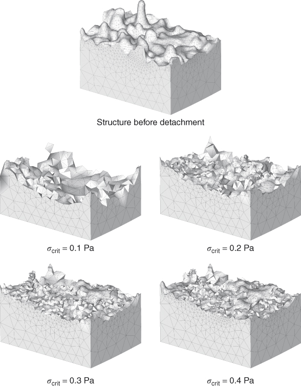
Figure 11.1 Biofilm structure before and after detachment at different strengths σcrit.
(Böl et al. (26) Figure 7. Reproduced with permission of John Wiley and Sons, Inc.)
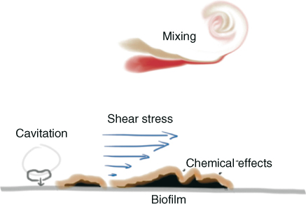
Figure 11.2 Sketch of the removed mechanisms of a biofilm from a surface. The biofilm may be attacked chemically, after which the consumed irrigant has to be replaced by mixing with fresh irrigant. Refreshment of the irrigant involves a flow that exerts shear stress on the wall. Finally, cavitation (formation and collapse of bubbles) may enhance the biofilm removal locally.
Sonic, ultrasonic, and laser activated irrigation systems
Sonic activation: operational characteristics
Sonic activation makes use of instruments that have an enforced vibration at one end (at the handpiece) and are allowed to vibrate freely at the other end. Sonic devices operate at audible frequencies
(below 20 kHz) and have file oscillation amplitudes up to 1 mm (22). The sonically driven instruments exhibit a simple bending pattern, consisting of a large amplitude at the tip (antinode) and a small amplitude at the driven end (node) where the piezo-actuation takes place (31) (Figure 11.3). Because the amplitude at the antinode may be as large as 1 mm, which is larger than the diameter of a root canal, frequent wall contact occurs resulting in reduced effectiveness (22).
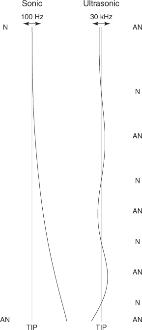
Figure 11.3 The sonically and ultrasonically driven instruments exhibit distinct patterns of nodes (N) and antinodes (AN). The exact pattern depends on the file geometry and material properties. The displacement is largest at the tip.
Ultrasonic activation: operational characteristics
Like sonic activation, the instruments used during ultrasonic activation have an enforced vibration at one end (at the handpiece) and are allowed to vibrate freely at the other end. Ultrasonic devices operate at higher frequencies (typically 20–200 kHz) and have amplitudes less than 100 µm (23, 32, 33). The higher frequency employed by ultrasonic activation leads to a more complex pattern of nodes and antinodes than those of sonic devices. Instruments driven by a piezoelectric element near 30 kHz exhibit a pattern of approximately three wavelengths, or six nodes and antinodes spaced approximately 5 mm apart (23) (Figure 11.3). The exact oscillation pattern depends on the instrument geometry and material. The oscillation amplitude of the tip of such instruments is on the order of 10–100 µm in the direction of oscillation; there is also an oscillation perpendicular to the main oscillation direction with a relative amplitude of approximately 10% (23, 34).
The cross-section of instruments available for ultrasonic activation is circular or square. Instruments with a square cross-section are mostly cutting because they are originally used for instrumentation of the root canal and consequently have an associated risk of damage to the root canal wall when used for irrigation purposes. In 1980, Weller et al. (35) proposed a smooth instrument and intentional wall contact; however, it was shown later that when intentional contact was prevented, irrigant streaming improved (36). Recently, it has been demonstrated in an in-vitro study involving 30 endodontists that contact with a root canal wall nearly always takes place, albeit unintentional. The amount of contact depends not only on the power setting used, but also on the instrument stiffness and on the force with which the instrument is pushed against the root canal wall. But light contact should not affect its cleaning mechanisms of streaming and cavitation, as the file oscillation is not damped out. Instead, it builds up a secondary oscillation at audible frequencies during which the file displaces away from the wall and keeps oscillating at the driving ultrasonic frequency (37). The term ultrasonic activated irrigation (UAI) has been suggested to replace passive ultrasonic irrigation (PUI) in order to avoid confusion.
Laser activation: operational characteristics
Another technique for cleaning the root canal system is LAI, which employs laser energy to agitate the irrigant. These lasers are typically of the type Er:YAG or ErCrYSGG, with a wavelength in the infrared region (2796–2940 nm) that is absorbed well in water (38). The dynamics of LAI have been studied using high-speed imaging (24, 25) showing the generation and implosion of a large vapor bubble at the tip of the fiber, generated by the absorption of laser energy and fast heating of the irrigant. The collapse of this bubble may induce a shock wave and additional bubbles throughout the root canal system. The laser fiber tip may be placed near the apex of the root canal, or in the pulp chamber with normal fibers or specially developed fibers (photon-initiated photoacoustic streaming, PIPS) (39, 40).
Laser activated irrigation is an indirect technique, not relying on direct ablation of the biomaterial.
Flow characterization during sonic, ultrasonic, and laser activated irrigation
Sonic and ultrasonic activation
The sonic or ultrasonic oscillation of an instrument induces streaming of the fluid around it, which leads to alternating pressures and shear stresses on the root canal wall. The streaming also gives rise to the mixing of the irrigant, so that irrigant consumed during its reaction with biomaterial is replaced by fresh irrigant. When ultrasonically activated needles or a continuous flow in the pulp chamber is used, the irrigant will also be refreshed.
The pattern of nodes and antinodes along the instrument determines the flow around the file in the axial direction (Figure 11.4). The single antinode and node displayed by instruments driven sonically can induce a flow from the tip to the driven end of the file. The multitude of antinodes and nodes on an ultrasonically driven instrument leads to a more complex pattern of microstreaming along the instrument. The lateral flow induced by both instruments is advantageous for cleaning lateral extensions (lateral canals, isthmuses, oval extensions) of the root canal (41), which are difficult to clean with a flow created by positive (syringe) or negative pressure irrigation (41).
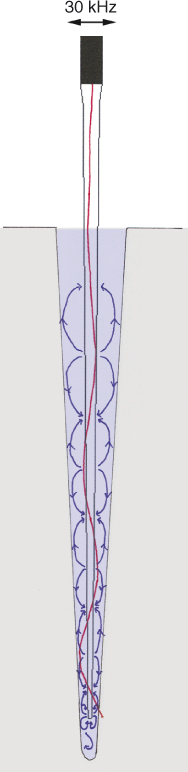
Figure 11.4 Microstreaming (blue arrows) induced inside a root canal model by an ultrasonically oscillating file that exhibits a pattern of nodes and antinodes (red line).
Neither sonic nor ultrasonic activation introduces a large fluid velocity into the apical direction (42), making extrusion of the irrigant unlikely. On the other hand, it necessitates the placement of these files near the apex. Nevertheless, the mixing and refreshment of irrigants and dentin debris removal take place when the ultrasonically activated instrument is inserted until 3 mm from working length (43).
The curvature of a root canal may affect the cleaning of the apical area (44), mostly because of the limited access for the instrument. When an instrument is inserted to or near working length, its oscillation may be affected by severe contact or binding of the instrument with the root canal wall (45). Therefore, it is advised to insert the ultrasonically driven instrument just in the beginning of the curvature without bending the instrument. The flow itself should not be affected by the curvature, because the radius of curvature is typically much larger than the scale on which the streaming takes place (43).
Increasing the intensity of the ultrasound will result in more effective cleaning (46).
Acoustic streaming
Lateral streaming is induced at each of the antinodes along the file; this lateral component of the flow is typically much stronger than the axial component. Acoustic streaming is a phenomenon already introduced in 1884 by Rayleigh (47) and extended to the case of a cylinder oscillating with high amplitude (48) inside another cylinder (49, 50). Ultrasonic cleaning with acoustic streaming induced by an oscillating cylindrical object was already described by Williams and Nyborg in 1970 (51, 52), who used a thin, oscillating capillary or tungsten wire to remove biomaterial from a surface.
Typically, acoustic streaming is a superposition of two flows, one being an oscillatory component and the other a steady component whose strengths depend on the oscillation amplitude. A simple theory of acoustic streaming was used by Ahmad and coworkers (53) to support ultrasonic activation in endodontics; however, only the steady part of the flow was considered. It was shown recently that it is crucial to also include the oscillatory component (54) (Figure 11.5).
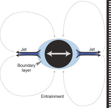
Figure 11.5 Schematic representation of the acoustic streaming that is induced by an ultrasonically oscillating instrument (black circle). Near the instrument there is a boundary layer in which the fluid oscillates together with the file (oscillatory component). In the direction of oscillation, jets are formed (steady component) that may impact on a nearby root canal wall and flow back toward the file (steady component) (entrainment).
The oscillatory part of the acoustic streaming makes the flow oscillate forward and backward together with the file. In doing so, the fluid exerts an alternating pressure and shear stress on (the material on) the root canal wall. The fluid near the file oscillates with the same velocity (u_o) as the file

where A is the oscillation amplitude (in m) and ω the oscillation frequency (in Hz). This velocity decreases rapidly with the distance from the file. The pressure and shear stress on a nearby wall can be of the order of 100 and 1 kPa, respectively (54), which is larger than the typical biofilm attachment strengths as reported earlier. The values for the pressure and the shear stress are similar to those reported for syringe irrigation using a very high flow rate (0.26 ml/s) (11); however, for syringe irrigation these forces occur only near the outlet of the needle, whereas for ultrasonic activation these forces are present near every nodal section of the instrument. The oscillatory nature of the pressure and the shear stress may furthermore induce fatigue to the material that needs to be removed from the root canal wall (19). However, as the oscillatory component decreases rapidly with distance from the oscillating file, this effect is most pronounced when the file is close to the wall.
Nonlinear effects of the fluid lead to a steady (nonoscillatory) streaming (jets) in the direction of oscillation (55), with a velocity us:

where ω is the oscillation frequency (in Hz), y the oscillation amplitude (in m), and R the radius of the file (in m). The jet velocity is typically 1 m/s and increases with increasing amplitude or power setting (46).
This steady part of the flow is doing the actual transport and mixing of the fluid. The jets also exert a pressure (1 kPa) and shear stress (10 Pa) onto (the material on) the wall (54) even at relatively large distances from the instrument as the velocity of the jet decreases only slowly with increasing distance from the file. These values can be one or two orders of magnitude lower than the oscillatory components, depending on the proximity of the root canal wall, which has a significant effect on the streaming. The pressure is highest in the center of the jet; the shear stress is highest off-center, at a distance of 0.1 times the distance between the oscillating file and the wall (56, 57). Because of these jets, the direction of oscillation of the file should be taken into account in particular when cleaning oval canals, isthmuses, and lateral canals (55).
Acoustic streaming is induced for all of the cross-sectional designs of the current instruments, although the details of the streaming may change (58). Acoustic streaming or cavitation (see “Cavitation” section) is not possible for sonic activation because its frequency and associated oscillatory velocity are too low (22).
Cavitation
During the high-amplitude oscillation of the instrument during ultrasonic activation, cavitation may be induced. Cavitation is defined as the nucleation, the growth, and collapse of bubbles within a liquid (59, 60).
In order to create a vapor bubble, the stress within the liquid has to be larger than the tensile strength of the liquid, which is of the order of 107 Pa for pure water (61). However, in nonpure water (tap water, distilled water), there are often tiny pockets (cavitation nuclei) with entrapped gas on surfaces of walls or particles, from which it is much easier to grow bubbles (a process called heterogeneous cavitation), as only the ambient pressure of 105 Pa (plus the vapor pressure of 103 Pa) has to be overcome (59). The typical velocity u necessary to generate this negative pressure ΔP in a liquid of density ρ can be estimated from the Bernoulli relation:

In water, the velocity threshold is around 15 m/s, which is feasible with the current endodontic ultrasonic devices, but not with sonic devices (62).
Bubbles grow during the negative phase of a pressure wave and collapse when the pressure becomes positive. Near a solid hard wall, bubbles tend to collapse in the direction of the wall. Alternatively, during bubble collapse next to a soft wall (like a biofilm covering a wall), the soft material might be pulled from the wall toward the bubble (63). High-velocity jets (hundreds of meters per second), with associated local pressures of 1 GPa and shear stresses of 1 MPa (64) and shock waves, are reported to accompany the bubble collapse a.k.a. the water hammer effect (59, 65).
The bubble collapse can also trigger a couple of consecutive bubble growths and collapses, until it is damped out. T/>
Stay updated, free dental videos. Join our Telegram channel
VIDEdental - Online dental courses


