CHAPTER 10 Principles of Removable Partial Denture Design
Difference in Prosthesis Support and Influence on Design
Some of the biomechanical considerations of removable partial denture design were presented in Chapter 4. The strategy of selecting component parts for a partial denture to help control movement of the prosthesis under functional load has been highlighted as a method to be considered for logical partial denture design. The requirements for movement control are generally functions of whether the prosthesis will be tooth supported or tooth-tissue supported.
Differentiation Between Two Main Types of Removable Partial Dentures
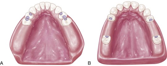
On the basis of the previous discussion, it is clear that two distinctly different types of RPDs exist. Certain points of difference are present between Kennedy Class I and Class II types of partial dentures on the one hand and the Class III type of partial denture on the other. The first consideration is the manner in which each is supported. The Class I type and the distal extension side of the Class II type derive their primary support from tissues underlying the base and secondary support from the abutment teeth (Figure 10-1, A and Figure 10-2). The Class III type derives all of its support from the abutment teeth (Figure 10-1, B and Figure 10-2).
Differences in Support
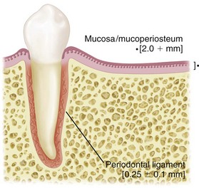
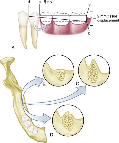
The distal extension partial denture derives its major support from the residual ridge with its fibrous connective tissue covering. The length and contour of the residual ridge significantly influence the amount of available support and stability (Figure 10-3). Some areas of this residual ridge are firm, with limited displaceability, whereas other areas are displaceable, depending on the thickness and structural character of the tissues overlying the residual alveolar bone. The movement of the base under function determines the occlusal efficiency of the partial denture and also the degree to which the abutment teeth are subjected to torque and tipping stresses.
Impression Registration
Differences in Clasp Design
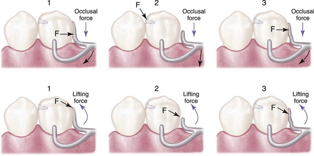
In the combination tooth and tissue–supported RPD, because of the anticipated functional movement of the distal extension base, the direct retainer adjacent to the distal extension base must perform still another function, in addition to resisting vertical displacement. Because of the lack of tooth support distally, the denture base will move tissue-ward under function proportionate to the quality (displaceability) of the supporting soft tissues, the accuracy of the denture base, and the total occlusal load applied. Because of this tissue-ward movement, those elements of a clasp that lie in an undercut area mesial to the fulcrum for a distal extension (as is often seen with a distal rest) must be able to flex sufficiently to dissipate stresses that otherwise would be transmitted directly to the abutment tooth as leverage. On the other hand, a clasp used in conjunction with a mesial rest may not transmit as much stress to the abutment tooth because of the reduction in leverage forces that results from a change in the fulcrum position. This serves the purpose of reducing or “breaking” the stress, hence the term stress-breakers, and is a strategy that is often incorporated into partial denture designs through various means. Some dentists strongly believe that a stress-breaker is the best means of preventing leverage from being transmitted to the abutment teeth. Others believe just as strongly that a wrought-wire or bar-type retentive arm more effectively accomplishes this purpose with greater simplicity and ease of application. A retentive clasp arm made of wrought wire can flex more readily in all directions than can the cast half-round clasp arm. Thereby, it may more effectively dissipate those stresses that would otherwise be transmitted to the abutment tooth. A discussion of the limitations of stress-breakers has been presented in Chapter 9.
The amount of stress transferred to the supporting edentulous ridge(s) and the abutment teeth will depend on: (1) the direction and magnitude of the force; (2) the length of the denture base lever arm(s); (3) the quality of resistance (support from the edentulous ridges and remaining natural teeth); and (4) the design characteristics of the partial denture. As was stated in Chapter 7, the location of the rest, the design of the minor connector as it relates to its corresponding guiding plane, and the location of the retentive arm are all factors that influence how a clasp system functions. The greater the surface area contact of each minor connector to its corresponding guiding plane, the more horizontal the distribution of force (Figure 10-4).
Essentials of Partial Denture Design
In developing the design, it is first necessary to determine how the partial denture is to be supported. In an entirely tooth-supported partial denture, the most ideal location for the support units (rests) is on prepared rest seats on the occlusal, cingulum, or incisal surface of the abutment adjacent to each edentulous space (see Figure 10-1, B). The type of rest and amount of support required must be based on interpretation of the diagnostic data collected from the patient. In evaluating the potential support that an abutment tooth can provide, consideration should be given to (1) periodontal health; (2) crown and root morphologies; (3) crown-to-root ratio; (4) bone index area (how tooth has responded to previous stress); (5) location of the tooth in the arch; (6) relationship of the tooth to other support units (length of edentulous span); and (7) the opposing dentition. (For a more in-depth understanding of these considerations, review Chapters 6 and 12.)
In a tooth and tissue–supported partial denture, attention to these same considerations must be given to the abutment teeth. However, equitable support must come from the edentulous ridge areas. In evaluating the potential support available from edentulous ridge areas, consideration must be given to (1) the quality of the residual ridge, which includes contour and quality of the supporting bone (how the bone has responded to previous stress) and quality of the supporting mucosa; (2) the extent to which the residual ridge will be covered by the denture base; (3) the type and accuracy of the impression registration; (4) the accuracy of the denture base; (5) the design characteristics of the component parts of the partial denture framework; and (6) the anticipated occlusal load. A full explanation of tissue support for extension base partial dentures is found in Chapter 16.
Denture base areas adjacent to abutment teeth are primarily tooth supported. As one proceeds away from the abutment teeth, they become more tissue supported. Therefore it is necessary to incorporate characteristics in the partial denture design that will distribute the functional load equitably between the abutment teeth and the supporting tissues of the edentulous ridge. Locating tooth support units (rests) on the principal abutment teeth and designing the minor connectors that are adjacent to the edentulous areas to contact the guiding planes in such a manner that the functional load is dispersed equitably between the available tooth and tissue supporting units will provide designs with controlled distribution of support (see Figure 10-4).
The second step in systematic development of the design for any removable partial denture is to connect the tooth and tissue support units. This connection is facilitated by designing and locating major and minor connectors in compliance with the basic principles and concepts presented in Chapter 5. Major connectors must be rigid so that forces applied to any portion of the denture can be effectively distributed to the supporting structures. Minor connectors arising from the major connector make it possible to transfer functional stress to each abutment tooth through its connection to the corresponding rest and also to transfer the effects of the retainers, rests, and stabilizing components to the remainder of the denture and throughout the dental arch.
The third step is to determine how the removable partial denture is to be retained. The retention must be sufficient to resist reasonable dislodging forces. As was stated in Chapter 7, retention is accomplished by placement of mechanical retaining elements (clasps) on the abutment teeth and by the intimate relationship of the denture bases and major connectors (maxillary) with the underlying tissues. The key to selecting a successful clasp design for any given situation is to choose one that will (1) avoid direct transmission of tipping or torquing forces to the abutment; (2) ac/>
Stay updated, free dental videos. Join our Telegram channel

VIDEdental - Online dental courses


