Management of non-surgical root-canal treatment failure
• the rationale for retreatment was established in Chapter 3
• the decision-making process and planning for retreatment were discussed in Chapter 5
• non-surgical and surgical retreatment armamentaria were described in Chapter 6
• the general principles of non-surgical root-canal treatment were discussed in Chapter 8.
Diagnosis of non-surgical root-canal treatment failure
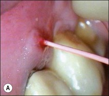
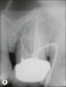
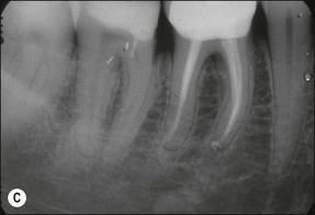
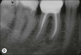
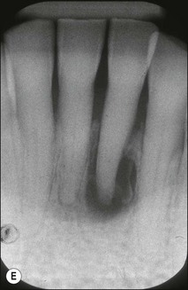
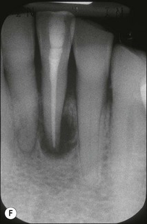
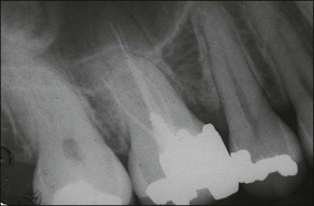
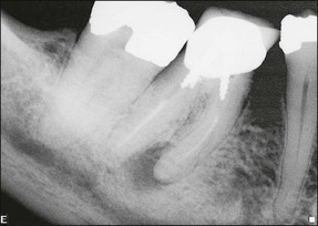
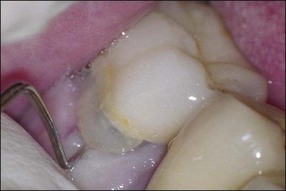
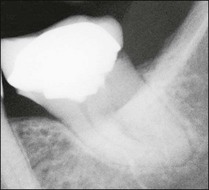
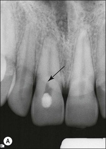
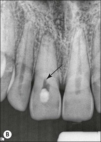
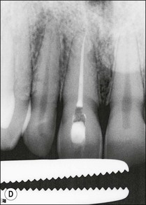
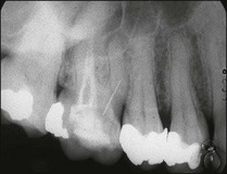
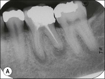
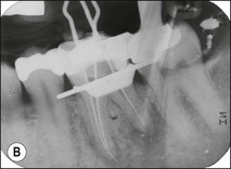
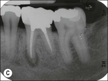
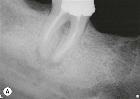
Non-surgical root-canal treatment failure is diagnosed based on the following clinical and radiographic criteria (Fig. 9.1):
• presence of clinical signs (swelling, sinus, tenderness to pressure or percussion) and/or symptoms (pain of endodontic origin)
• enlargement of existing periradicular radiolucent lesion associated with the tooth
• development of new periradicular radiolucent lesion associated with the tooth
• persistence of periradicular radiolucent lesion associated with a tooth that had root-canal treatment at least 4 years previously.
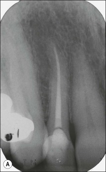
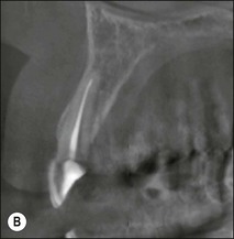
It is of the utmost importance to distinguish persistent pain of endodontic origin from chronic non-odontogenic, neuropathic or neuromuscular pain by adopting the assessment approaches described in Chapters 4 and 16. The two-dimensional limitations of conventional periapical radiography may be overcome by three-dimensional cone-beam-computerized tomography (CBCT) to increase sensitivity, if necessary, for confirmation of the periapical status of root-treated teeth exhibiting no obvious periapical radiolucency but associated with persistent pain (Fig. 9.2).
Decision-making process
i. judgement about what is wrong with the tooth: factors to decide on will include the presence of a crack, and whether the infection is likely to be intraradicular or extraradicular or whether some other pathosis is at play
ii. judgement about treatment options and the correct choice: factors to decide on will include whether the dentist can improve upon previous root-canal treatment and, if so, in what way; non-surgical retreatment may involve removal of restorations, retention aids, root-filling material and correcting iatrogenic problems
iii. judgement about prognosis of different options in their hands: the dentist will need to be sure that the tooth is predictably restorable and a viable future unit, as well as determine how each treatment option could be executed together with a realistic prognosis
iv. judgement about prognosis in the hands of specialist(s): if the dentist is unsure about the prognosis in their hands, they should offer referral to a specialist who may be able to provide the complex care with a better prognosis
v. cost of different options: the dentist will need first to visualise the procedures virtually, in the mind’s eye, to assess the practical process, resource and time required. The better versed and experienced they are the more precise their estimation.
Non-surgical root-canal retreatment
Indications for non-surgical root-canal retreatment
Non-surgical root-canal retreatment is indicated under the following three circumstances:
1. when, having confirmed treatment failure, it is judged that the residual infection is principally intraradicular and that it is accessible through a conventional access, having negotiated any obstructions. It is self-evident that this decision presupposes that obstructions can be removed or bypassed without compromising the remaining tooth structure; the purpose is to treat the residual infection
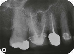
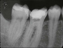
2. when a new and complex restoration is required for a tooth with a technically poor root filling (Fig. 9.3) but which exhibits no evidence of pathoses or symptoms; the purpose is to correct the technical quality of the root-canal treatment, as the ownership will lie with the restoring dentist
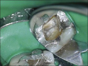
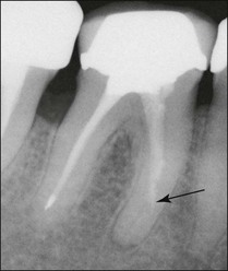
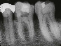
3. when it is suspected that a tooth with an adequate or inadequate root filling has been contaminated due to leakage or loss of its restoration (Fig. 9.4); the purpose is to decontaminate the root-canal system and place a new root filling and restoration.
Principles of root-canal retreatment
1. the resident infection is likely to have been altered through artificial selection to one with a reduced diversity, dominated by Gram-positive bacteria, and a microbiota that is more difficult to eradicate
2. access to the residual infection may be compromised by the presence of various types of obstructions, including dentine debris, iatrogenic errors in preparation, root-filling material, radicular dowel and restorative material
3. the tactile feel of the natural canal will have been altered through changes in shape, packed organic/inorganic debris, iatrogenic conditions, chemical treatment, impacted foreign materials.
The specific principles of root-canal retreatment are therefore to:
1. remove all restorative material as atraumatically as possible, where possible sacrificing restorative material rather than tooth structure; the exception will be when a new and sound restoration has recently been placed and can be excluded as part of the aetiology
2. assess the restorability of the tooth and, if deemed so (see Chapter 14), stabilize it for root-canal retreatment to prevent recontamination during treatment
3. remove all root-filling material without sacrificing any additional dentine, if possible; the exception will be only if the canals were previously inadequately prepared but, even under those circumstances, avoid instrumenting dentine at this stage; it will be easier to determine iatrogenic errors as belonging to the previous procedure
4. gauge the canal to understand its previous shaping and identify any missed anatomy or root canals once all root-filling material has been removed and apical patency and length of canal have been determined
5. refine and modify the shape of the root-canal system as necessary to deliver irrigant and root-filling material to the termini; the skills of gauging come into their own in such cases
6. complete root-canal treatment at this stage as if it were a de novo case; except if elements of obstruction could not be corrected.
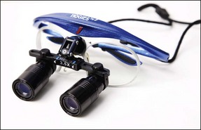
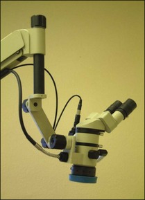
The most common error in non-surgical root-canal retreatment is removal of excessive dentine with the consequence of further weakening the tooth and creating new iatrogenic problems. It is critical to use some form of magnification when required; for example, for creating a trough of dentine around a post or fractured instrument requires good magnification (Figs 9.5, 9.6), good lighting, and a steady hand. Longer appointments are required for retreatment cases, in particular for removal of foreign material from root canals.
Removal of coronal restorations
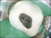
All coronal restorations should be removed prior to treatment if they are either leaking or if caries is present (Figs 9.7, 9.8). This also applies to full coverage crowns. If the restoration is sound it is better to leave it in place during treatment and access the pulp chamber through the restoration. It is easier to place a rubber dam and to keep the operating field dry by cutting through an existing restoration (Figs 9.9, 9.10).
Removal of bridges
Any bridge that has become decemented must be removed. In most cases, when an abutment tooth requires retreatment, the patient should be forewarned of the possible need for a new bridge. If a new bridge is already planned then it is immaterial if it is damaged during its removal, providing an adequate temporary bridge can be constructed and placed. The easiest method for removing a bridge is to make a vertical cut through the retainer on the buccal aspect and then to break the cement lute with an instrument, such as a Mitchell’s trimmer by inserting it into the cut and twisting the blade. There are, however, many devices (see Fig. 6.17) which can be used to remove bridges – most of them causing both the operator and patient varying degrees of aggravation.
Removal of posts
There are many different systems and gadgets on the market specifically made for the removal of posts (see Fig. 6.18). The success and ease of removal depends on the type, length, quality of fit of the posts and the cement material. Posts can be broadly classified into prefabricated or custom laboratory-made cast metal posts. Prefabricated posts include screw or cemented wrought gold, stainless steel or titanium metal posts, zirconia ceramic posts, or carbon or glass (quartz) fibre posts. Ceramic and fibre posts are likely to be used with aesthetic ceramic crowns and have a lower radiodensity than stainless steel or gold posts.
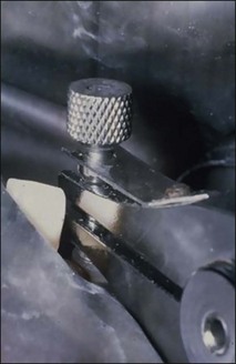
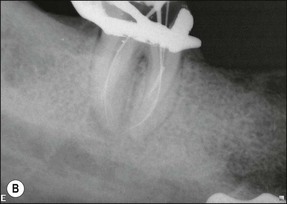
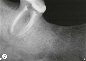
For metal posts, first attempts at removal are usually made by use of ultrasonic vibration. The crown is first removed by cutting a vertical slot to allow leverage and expansion of the margins. Excess cement is then taken away. A solid curved tip is inserted in the ultrasonic hand-piece and applied gently around the incisal edge of the core under water coolant (Fig. 9.11). The power is varied while the ultrasonic tip is in contact with the core to achieve the desired effect. When the right power setting is reached, cement particles may be observed vibrating at the base of the core. If this does not loosen the post after a few minutes, a fine tip can be used to cut a narrow trough around the post to reduce the retention (Fig. 9.12a,b). The first step is then repeated with the blunt tip. This procedure will remove the majority of posts (Fig. 9.12c). In the case of an excessively long, non-threaded post, when ultrasonic vibration is not successful, one of the post-extracting devices may have to be used (Fig. 9.13).
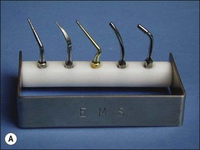
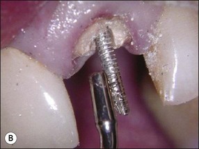
Fig. 9.11 (a) Ultrasonic tips; (b) ultrasonic tip applied to a post (predictable restorability may be questionable)
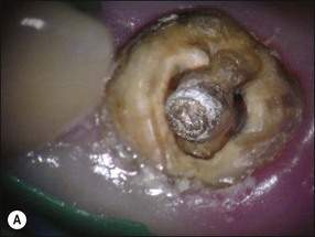
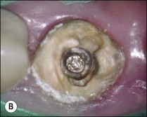
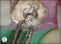
Fig. 9.12 (a) Post fractured at canal orifice; (b) troughing cut around post with ultrasonic file; (c) loosened post removed with fine-beaked forceps (predictble restorability may be questionable)
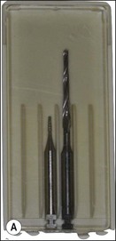
Ceramic posts are likely to be cemented with resin- or glass ionomer-based cements. Well-fitting ceramic posts with resin cement are extremely difficult to remove. Fibre posts are much easier to remove than metal, they can be disintegrated by applying ultrasonic tips, Piezo or Gates–Glidden drills, a small stainless steel rosehead bur or specially designed drills (DT Light-post removal kit, Bisco, Inc., Schaumburg, IL, USA) into the centre of the post (Fig. 9.14).
Removing gutta-percha
The first stage of removing well-condensed gutta-percha (GP) involves gaining access to the pulp chamber and clearing it. This may be accomplished with a high-speed bur and hand excavators. A GP root filling that has been in place for many years tends to become vulcanized and can be brittle and hard, making it more difficult to remove. Ultrasonic tips, nickel–titanium orifice openers, Hedstroem files and chloroform are useful for removing gutta-percha (Fig. 9.15). There are three stages to the procedure:
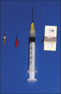
Fig. 9.15 Nickel–titanium orifice openers, Hedstroem files and chloroform are useful for gutta-percha removal
1. A simple way to remove the coronal bulk of the GP is to use a narrow ultrasonic fine scaler tip or a nickel–titanium rotary instrument (Fig. 9.16a–c)
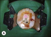
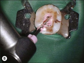

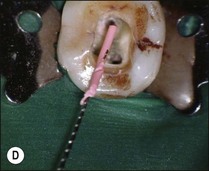
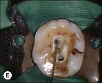
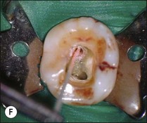
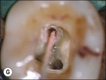
Fig. 9.16 (a) Gutta-percha in distal canal; (b) orifice opener removing gutta-percha with hand-piece – speed at 700 rpm; (c) set hand-piece speed at 700 rpm for gutta-percha removal; (d) apical portion of gutta-percha removed with Hedstroem file; (e) chloroform placed in canal entrance using a syringe; (f) file placed in canal to mix chloroform and gutta-percha then wicked with paper points; (g) remaining gutta-percha dissolved in chloroform and wicked with paper points
2. Most of the remaining bulk of the GP can be removed with Hedstroem files (Fig. 9.16d). The largest file that will not bind to the canal wall is placed in the canal and rotated by hand to engage the GP only. The depth of penetration required can be judged from the preoperative radiograph but mostly by tactile feel
3. The final stage consists of “wicking” with paper points, once the bulk of the gutta-percha has already been removed. The canal is flooded with chloroform from a disposable dispenser (Fig. 9.16e) to dissolve remaining tags of gutta-percha adhering to the canal walls. The chloroform should not overflow the pulp chamber otherwise the rubber dam may be dissolved. The chloroform is then stirred using a small hand file to ensure the solution dissolves the GP completely (Fig. 9.16f). The largest paper points that fit into the canal are then selected and used to soak up the dissolved mass. Wicking is achieved by inserting several points one after the other into the canal (Fig. 9.16g). The process is repeated until no further pink discoloration is discerned on the paper points. The canal is then thoroughly washed with irrigants.
Negotiating a ledge
When the previous root filling is short of the apex, there may either be a ledge or debris packed into the canal. It may be possible to detect a ledge radiographically if the angle is favourable (Fig. 9.17). Deviation of the apical extent of the root filling from the centre may be suggestive of a ledge. Ledges may be negotiated once the coronal portion of the canal has been cleaned out; a size 08 or 10 stainless steel file with a sharp precurve at the tip may be used to explore for the canal opening. Once found it is threaded in and is worked gently to file away the ledge (Fig. 9.18).
Packed dentine debris
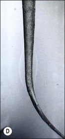
The aetiogenesis of a ledge is usually preceded by blockage of the canal by dentine debris (Fig. 9.19a). The first challenge is to detect and diagnose the presence of blockage by dentine debris, which can only be achieved by tactile sense. There is no easy method for unpicking the debris blockage except by the patient use of a small file in a deliberate, controlled but firm picking motion. This is facilitated by chemical dissolution with EDTA for the inorganic component and sodium hypochlorite for the organic component; the two should be used alternately in copious amounts and delivered by agitation with a file or if necessary with a well-fitting gutta-percha point. Should these measures fail, it may be worth trying a small precurved ultrasonically energized file to loosen the debris (Fig. 9.19b–d). The danger is that when the debris is packed very tightly it may be as hard as the surrounding dentine and attempts to remove it may result in a false canal leading to a perforation.
Sclerosed canals
1. additional, irregular tertiary dentine, which makes the canal narrower and the surface more irregular but retains the canal pathway for instrument negotiation
2. dentine tubule sclerosis, which makes the dentine harder to instrument but retains the canal pathway
3. dystrophic calcification of the pulp, which also narrows the canal irregularly but may be more prone to cause blockage.
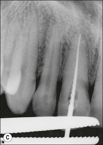
The key is that the canal orifice should be located first. Once located, the challenge is patiently to negotiate it to its length by gentle stem-winding of size 06, 08, 10 hand files with lubricant containing EDTA. When the file begins to meet resistance, a larger file is sensitively advanced and the procedure repeated; the steps are size 10, 15, 20 and then back to size 06, 08, 10. The goal is to eliminate coronal binding likely to be the cause of interrupted advancement. It is cases such as these that demand tactile skills, for which there is no technological substitute (Fig. 9.20).
Removal of metal instruments and silver points
It should be emphasized that a fractured instrument in itself does not cause failure. It does not endanger the health of the patient nor itself produce any symptoms, providing it lies entirely within the canal system. If, however, it prevents access to the apical infection, then it will clearly compromise the potential for a favourable outcome and should be removed, if technically feasible without incurring further iatrogenic damage. A preoperative radiograph will show where the metallic object is located together with its conjunction. The simple classification below will help the operator decide how best to proceed. Examples are presented in Figures 9.21–9.23.
Class 2 lies within the straight part of the canal. An attempt is initially made to bypass the obstruction with a small hand file and lubricant. If the canal can be negotiated to the working length and prepared, it may not be necessary to remove the metallic object but simply to obturate the canal so that the object is embedded within the filling material. However, care should be taken not to push the bypassed material, which may have been detached from the canal wall/niche, into the apical tissue and compromise periapical healing (Fig. 9.24).
If the object cannot be bypassed, a narrow trough is cut around the embedded object with an ultrasonic tip. When the coronal 2.0 mm is exposed, it can be removed using an extractor or specifically designed instrument removal system (Fig. 9.25).
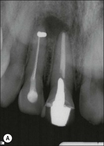
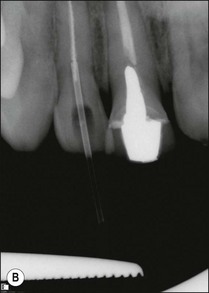
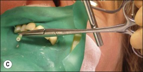
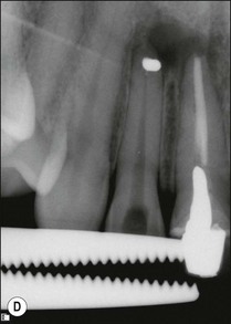

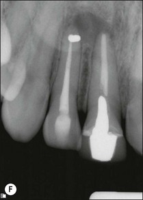
Fig. 9.25 (a) Fractured instrument embedded during retrograde amalgam placement in the 12; (b) Cancellier tube fitted over the exposed instrument; (c) Cancellier tube tapped out with artery forceps; (d) fractured instrument successfully removed; (e) Hedstroem file securely glued in Cancellier tube; (f) canal prepared and obturated
Class 3 lies beyond a curve in the canal. The majority of these metallic objects cannot be removed without excessive removal of dentine and risk of canal perforation. An attempt is made to bypass the fragment using a fine stainless steel file with a lubricant. A small curve is placed at the tip of the instrument to help locate a passage past the object. Canals are not round and, therefore, there should be a gap between the metal and the wall of the canal. Alternatively, it may sometimes be possible to thread an instrument into a spiral flute if it is large enough and not engaged into dentine. Once the instrument can be bypassed, larger instruments are used until the canal is prepared to the desired shape (Fig. 9.26).
Stay updated, free dental videos. Join our Telegram channel

VIDEdental - Online dental courses


