Laser physics and laser-tissue interaction
Luciano Bachmann – Denise Maria Zezell
Introduction
In this chapter we intend to describe the nature of laser light and its interactions with biological tissues. Our aim is to place physics inside a “black box” laser sale apparatus for non-specialist professionals; and to make the mechanism responsible for the effects observed after laser irradiation clear. Bearing the objectives in mind, we will make use of many graphical resources as well as common sense examples to aid the reader’s understanding of this issue.
Associations with common sense examples must be handled carefully because they are only analogies that will be used to describe the abstract concepts of physics and the interaction mechanism of laser with matter. For a more specialized theory about laser physics the reader must look in to other books [1,2] and search for laser-tissue interaction in [3,4].
Table 1.1 lists the physical parameters and the constants used in this chapter. One example is the name given to the energy distribution on a certain area.
This laser parameter has different names: energy density, radiant exposure, fluence, or dose. In this chapter we use the name that is recommended by the International Systems of Units [5]: radiant exposure, which is expressed in [J/m2]. In the same way the parameter representing the power distribution on a certain area will be designated: irradiance, and will be expressed as [W/m2].
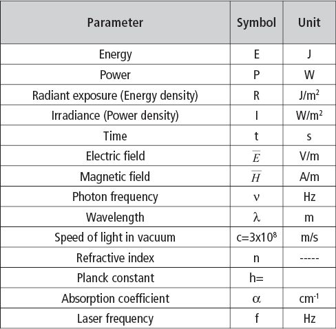
Table 1.1 • Physical parameters and constants used in this chapter.
Light Waves
Light emanating from sources, laser sources or not, is wavelike in nature.
To visualize the wave characteristic of light is not an easy task for non-specialists, but this concept will be clarified in this section.
Light can be described by a combination of time-varying propagation of electric (E) and magnetic (H) fields through space.
These fields oscillate at a certain frequency (ν); i. e., the field value increases and decreases ν times in one second.
The frequency at which these fields oscillate and their wavelength (λ) are related by: λν=c/n, where c is the speed of light in a medium with refractive index n.
To visualize the electric and magnetic (electromagnetic) field we can compare the action of this field with the gravitational field.
For example, a ball which falls down on the earth surface is in fact attracted by the earth, because the earth is “a bigger ball” with a larger mass than the ball, and both are attracted together.
Another mechanic example is a mass coupled with a spring: if our ball is coupled with a vertical spring suspended in the air, the ball does not fall to the earth surface; the spring restores the movement back up and the ball oscillates vertically to dissipate all the energy heating the environment.
The electromagnetic field acts likewise on the charges of atoms and molecules: when a positive (or negative) charge is placed under an electromagnetic field, it will be displaced from its position; when the field oscillates with frequency ν, the charge will also oscillate at the same frequency.
As we know, our body is fulfilled with charges. When an electromagnetic field interacts with our tissues, the molecules will oscillate at the same frequency of the wave. This will heat our body, trigger chemical reactions, or lead to other mechanisms.
In Figure 1.1 we can visualize the explanation for the electromagnetic field in the space (Figure 1.1a); and in time (Figure 1.1b). When a charge is submitted to the influence of a wave its movement can also be described by the electromagnetic wave observe Figure 1.1c and consider a positive charge at the origin; when the electric field vector of a wave, described by the arrow, interacts with the charge, its movement will follow the amplitude of the electric field. Figure 1.1c shows the electric field at a certain angle; if all photons have their electric field running in the same direction, the beam is named polarized beam; if the photons oscillate at a nonspecific direction, the beam is nonpolarized as represented in Figure 1.1d. The different frequency of the electromagnetic field will determine the energy of the wave (photon). The frequency range of different photons can be visualized in the upper scale in Figure 1.2; the second scales correspond to the energy, and the third to the wavelength.
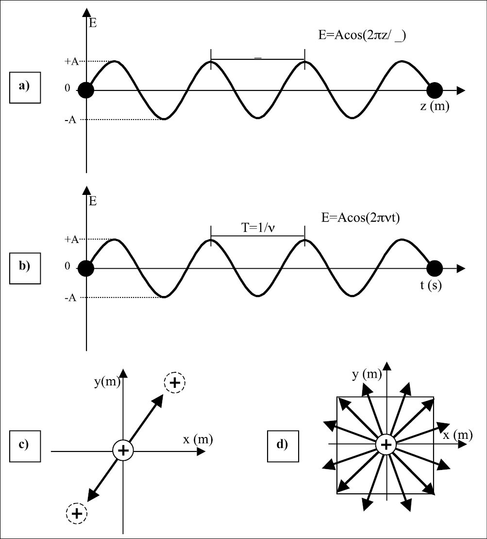
Figure 1.1 • a) The electromagnetic wave is a function of the distance at a certain time (t=0). The separation between two maxima of the wave amplitude is the wavelength λ. b) Amplitude of an electromagnetic wave as a function of time at a point in space (z=0). The period T is the time necessary for the wave to complete one cycle; i. e., starting from an amplitude +A, decreasing to –A and returning to the initial value +A. The inverse of the period is the frequency of the wave; i. e, number of cycles carried out in one second. c) Crossection of item (a) with representation of a positive charge displaced by the action of an electromagnetic field. If the wave oscillates in a determined direction, the electromagnetic field is named polarized, and the charge will be displaced in the same direction of the wave. Otherwise, if the wave is nonpolarized (item d), the wave can oscillate in any direction and therefore the charge will be displaced in any direction.
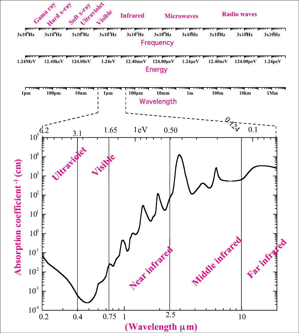
Figure 1.2 • Electromagnetic spectrum. The first upper scale represents the frequency of wave oscillation. The higher values represent the gamma ray and hard x-ray; when the frequency is decreased there are the soft x-ray, ultraviolet, visible, infrared, microwaves, and radio waves. The second scale represents the respective photon energy and the third gives the wavelength of the photon. The main interest in laser applications is the ultraviolet, visible, and infrared radiation; these three spectral regions are better visualized in the graphic and compared with the water absorption spectrum [6].
The correlation of the energy (E) of a photon with its frequency (ν) and wavelength (λ) is giving by the following equation:
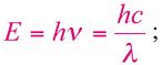
where h is the Planck constant (6.625×10⁻³⁴Js) and c is the speed of light. A more useful equation is:
where E is given in eV and λ in μm. In the same Figure 1.2, the most interesting spectral region for laser application is expanded and compared with the water absorption spectra (adapted from [6]).The absorption coefficient is expressed in cm-1, the wavelength of the photons can be visualized in the lower scale and is given in micrometers (µm), and the upper scale gives the photon energy in eV.
Laser physics
Laser design
Some basic conditions must be satisfied so that a functional laser system can be obtained. First of all there must be a material named active medium, that allows population inversion. It is unlikely that this inversion occurs in nature but it can occur in some materials. The most probable behavior for electrons is to remain at the ground energy level, whereas in an active medium excited electrons are located at a higher energy level for a longer period of time, allowing the stimulated emission. This phenomenon will described in the following paragraphs. In Figure 1.4 it is possible to visualize the description of the main instruments for a laser system. The active medium will be excited by means of a pumping source, which can be another laser, an electric current or a nonlaser source. When population inversion occurs, stimulated emission will take place and an avalanche of photons will emitted. These photons can resonate between the two mirrors; the output mirror is a partially reflected mirror, thus allowing photon emission.
Stimulated emission
In nature all systems tend to reach the lower energy state. A typical example is a rock on a hill; the rock tends to roll down to reach the valley, river, or the sea. Electrons act in the same way, occupying states with lower energy. This phenomenon is represented in Figure 1.5a; if the lower state is totally occupied, the second lower state will start being occupied. But when the system has more energy, like thermal energy, the electron can acquire this energy and transit to upper states. The origin of stimulated emission can be visualized in Figure 1.3 by four boxes. Figure 1.3a represents the nonexcited atom with its electron in the ground state. Stimulated absorption of one photon will excite the atom and the electron will transit to an upper energy state (Figure 1.3b). When a spontaneous emission occurs (Figure 1.3c) a photon will be emitted and will stimulate the emission of another photon (Figure 1.3d). For the stimulated emission to occur, it is necessary that the active medium presents population inversion. This situation is described by the energy-state-transition diagram of Figure 1.5c: the most populated state is not the ground state, but an upper state, named long-lived excited stated. With all the electrons in this upper state, stimulated emission can occur more efficiently, thus producing the laser beam.
Monochromaticity
The monochromaticity of laser light originates from the different energies during the stimulated emission described in Figure 1.3. When a photon is emitted spontaneously, its energy is well-defined and the other photons stimulated by the first one have the same energy. As a consequence, the laser beam output is composed of well-established photon energy; i. e., a specific wavelength. If the source does not emit photons with the same energy, the emission spectra will be broad as in the case of a LED (Light Emitting Diode) or the sun in Figure 1.7.
Directionality
Laser emission occurs only in the direction toward which the system resonates; i. e., in the longitudinal axis connecting by the first mirror to the two late-ral faces of the laser medium and the second mirror (Figure 1.6). Otherwise, photon emission can occur randomly at any direction in a lamp bulb, spreading out the energy: consequently leading to a much lower irradiance than that of a laser beam.
Coherence
Laser light has spatial and temporal coherence. This coherence means that all the photon waves that compose a laser pulse are correlated in space and time. As described before, all the photons oscillate at the same frequency (monochromaticity), and beyond this frequency oscillation of the laser photons starts at the same time. In other words, when the amplitude of the electric field of one photon (Figure 1.1b) is at its highest value, all photons have amplitude at this highest value too, which means temporal coherence.
Consider that in a certain position the amplitude of the electric field has a particular value. Spatial coherence means that at a certain time, all the other wave photons will have the same amplitude value at λ meters away from the first photon, and the next surrounding wave photons will also have the same amplitude value. Therefore, all photons will be correlated with the first photon. The origin of spatial and temporal coherence in a laser beam is described in Figure 1.8 and a common sense analogy to explain the coherence is presented in Figure 1.9.
Laser systems in life science
The main laser wavelengths applied in life science are listed in Table 1.2. The Excimer lasers, nitrogen, and higher harmonic of neodymium lasers emitting at the ultraviolet spectral region with the highest photon energy. The main interaction mechanism for these lasers is photoablation. There are laser systems with emission wavelengths in the visible spectral region and their main interaction mechanism can be described as photochemical. Finally, the laser systems with emission in the infrared spectral region exhibit an interaction mechanism dominated by thermal action. The photon energy changes with its wavelength. Fo/>
Stay updated, free dental videos. Join our Telegram channel
VIDEdental - Online dental courses


