3D diagnosis and SimPlant planning
3D planning of a single-tooth implant
Clinical examination is followed by extensive diagnostic investigations. Apart from dental cast analysis, radiographic diagnosis is of key importance: it should include at least a panoramic radiograph with measuring template and, best of all, a CBCT or CT scan.
The panoramic image already provides an overview of the anatomical situation (Fig 2-1a). However, 3D diagnosis and planning are far more precise and reliable on the CBCT image. The third dimension, the width of the residual ridge, can be seen on the cross-sectional image (Fig 2-1b).
In such cross sections, the implants can be aligned in the buccolingual direction, while alignment in the mesiodistal direction is generally performed using the panoramic radiograph. Based on the measurements in this case, a wide platform (WP) implant, 13 mm long and 5 mm in diameter, was planned for the replacement of tooth 45. For the provisional loading, a 1-mm high CeraOne (Nobel Biocare) abutment was planned as the connecting component for the provisional crown.
Detailed planning was performed using the SimPlant program (Dentsply). Here, the WP implant was taken from the program library (color code pale blue in this case), virtually placed into the jaw and adjusted in all the planes (Fig 2-1c). The CeraOne abutment (color code pink) was also virtually placed onto the implant. For better visualization of the forces involved, the extension of the implant axis is represented as a yellow bar. If the structures lying behind the implant or in the same plane are to remain visible, the implant can be shown in outline only (Fig 2-1d). The inferior alveolar nerve, as the most important anatomical structure in the mandible, can be marked, allowing its course in relation to the planned implants to be assessed (Fig 2-1e). The marked nerve also appears on the cross-sectional images, so that its position relative to the implants can also be accurately evaluated in this plane (Fig 2-1f).
Moreover, the 3D reconstruction gives a very vivid visual depiction of the positioning of the implants and their relation to the nerve. In this mode, the bone structure can be shown in semi-transparent view (Fig 2-1g) or can even be faded out completely, to visualize the relationship of the implants to the nerve in isolation (Fig 2-1h).
For the treatment course, see page 60.
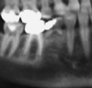
Fig 2-1a Section from the panoramic radiograph.
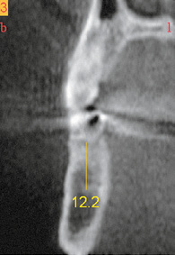
Fig 2-1b Cross section through the jaw.
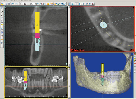
Fig 2-1c SimPlant planning.
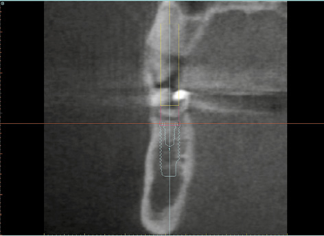
Fig 2-1d Outline of the planned implant on the cross section.
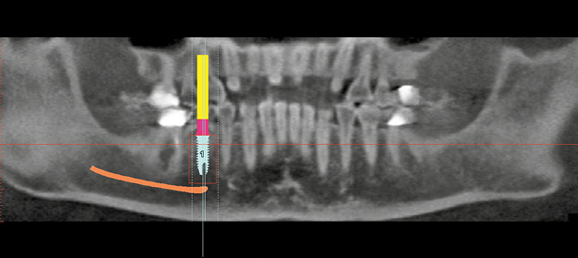
Fig 2-1e Marked inferior alveolar nerve.
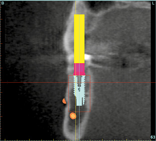
Fig 2-1f The implant in relation to the nerve in the cross-sectional view.
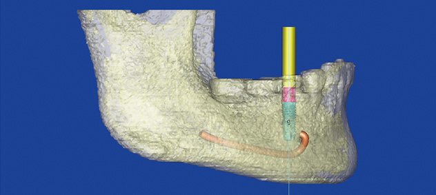
Fig 2-1g Relation of the implant to the nerve in a semi-transparent view of the jaw.
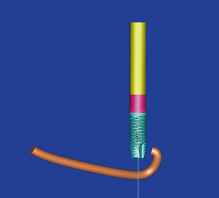
Fig 2-1h Relation of the implant to the nerve in isolation, with the bone faded out.
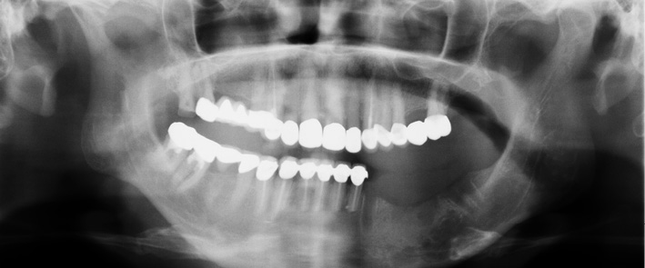
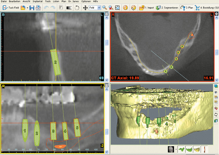
Fig 2-1j SimPlant planning.
3D planning of a free-end situation
The free-end situation is one of the most common indications for implant treatment in the mandible. In view of the large number of implants needed in this kind of situation, each individual implant needs to be planned with great care. Apart from the position of the nerve, another factor of key planning significance is the width of the residual ridge. In the case described here, a large mandibular defect had developed following the loss of implants placed at another clinic. The planned treatment included not only the insertion of five implants, but also extensive augmentation. The panoramic radiograph alone clearly showed the extent of the defect (Fig 2-1i). A much more accurate assessment of the situation can be obtained from the CBCT image in the SimPlant planning program (Fig 2-1j). The five planned implants need to be placed in such a way as to use all the available bone (Fig 2-1k). In order to achieve primary stability in the previously damaged, knife-edge jaw after the insertion, the plan was to use narrow platform (NP) implants with a diameter of 3.3 mm. Implants 1 and 3 are only weakly anchored in the bone and need augmentation on the buccal side (Figs 2-1l to 2-1n). The 3D reconstruction provided an insight into the intraoperative situation following insertion of the implants, and showed not only the extent of the defect but also how much bone needed to be augmented (Fig 2-1o).
For the treatment course, see page 70.
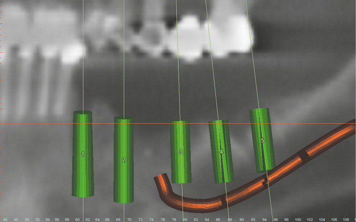
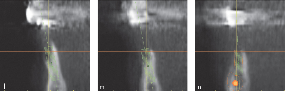
Fig 2-1l to 2-1n Cross sections of the jaw with the first three implants.
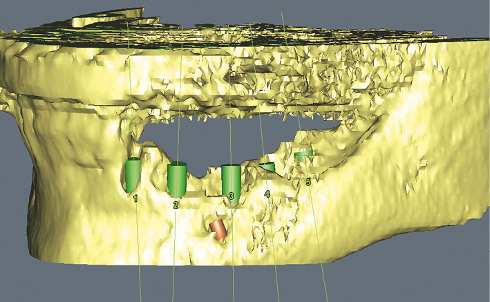
Fig 2-1o 3D reconstruction with the virtually inserted implants.
Single-tooth gap
In the case of a single-tooth gap, the preoperative diagnostic investigations need to assess not only the location of the nerve, but also the extent of the gap in the mesiodistal direction and the available bone supply in the buccolingual (or labiolingual) dimension. The mesiodistal width of the gap can be determined exactly on the dental cast and approximately on the panoramic radiograph. The buccolingual width of the residual ridge can be determined on the model only in the coronal region, following a determination of mucosal thickness, whereas the panoramic radiograph provides no information on this aspect. Moreover, measuring mucosal thickness in the posterior tooth region is difficult for the dental surgeon, unpleasant for the patient and beset with errors. Thanks to modern 3D imaging techniques, it is now possible to determine the exact width and height of the residual ridge, as well as the position of the nerve, on the CT or CBCT scan images (see page 40).
Either premolars or molars may be replaced in the posterior region. The first molar is a far more common candidate for implantological restoration than the second molar. The first molar is at the center of the masticatory forces, and is thus exposed to a high level of stress. As a result, a single regular platform (RP) implant (diameter 3.75 mm) may become overloaded. Therefore, where sufficient space is available, a WP implant of increased diameter (5 mm) or two RP or even NP implants (diameter 3.3 mm) represent better alternatives. The use of two implants is generally preferable if the residual ridge is inherently narrow and the distance between neighboring teeth is >11 mm, whereas one implant should be the preferred option if the gap is <10 mm and the residual ridge is on the wider side. The considerations involved in replacing the first molar are difficult to reconcile with the rules set out by Dr Tarnow, which state that the distance between two implants should be at least 2 mm, and the distance to the neighboring tooth at least 1.5 mm.
Typical treatment course
Replacing a molar with two implants
Baseline situation
Moderate residual ridge atrophy was diagnosed in this 36-year-old man with missing tooth 46 (Fig 2-2a) The gap in the root region was suitable for the insertion of both one WP implant and two RP or NP implants into the extraction sockets (Fig 2-2b). While the well-maintained width of the residual ridge, which is clearly shown on the CT cross section (Fig 2-2c), would allow a wider WP implant to be inserted, it was decided to insert two implants for stability reasons.
Diagnostic tools
- Clinical examination
- CBCT
- SimPlant planning
- Dental cast analysis
Treatment plan
1.Insertion of two implants, transmucosal healing
2.Prosthetic loading with a metal-ceramic crown on customized abutments
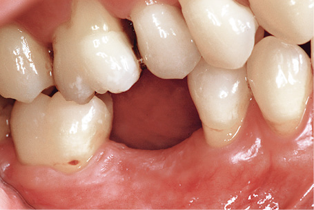
Fig 2-2a Clinical baseline situation – moderate residual ridge atrophy.
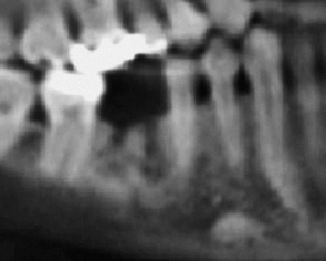
Fig 2-2b Panoramic radiograph section – gap for two implants.
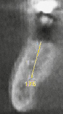
Fig 2-2c Adequate residual ridge width.
Implant placement
Two Neoss implants were inserted into gap 46 under local anesthesia (Fig 2-2d). The implants were placed at the desired depth and the remaining bone defect was filled with the harvested bone chips. The polyetheretherketone (PEEK) healing abutments were then screwed onto the implants. One of the healing abutments needed shaping on one side due to the limited space and convergence of the implants (Fig 2-2e). To protect the implants from undesirable stresses, it is important that there is neither any contact between the healing abutments and the neighboring teeth, nor any occlusal contact with the dentition in the opposing jaw (Fig 2-2f).
Attention: Where there is good bone quality and adequate primary stability, the implants may be directly fitted with healing abutments and allowed to heal transmucosally. If bone quality is poor, it is advisable to allow the implant to heal submerged and to expose them only after 4 to 6 months.
The postoperative panoramic radiograph shows the position of the implants relative to the neighboring teeth and demonstrates that there is adequate distance to the inferior alveolar nerve (Fig 2-2g). The final photograph shows the transocclusal, screw-retained metal-ceramic crown, which was first cemented onto the customized abutments (Fig 2-2h).
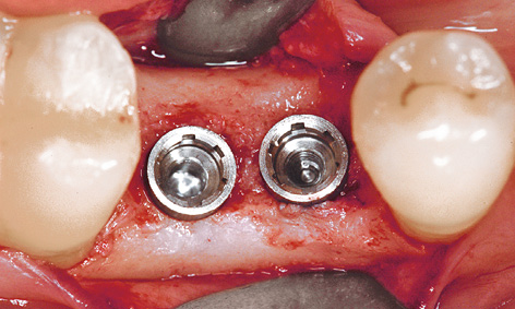
Fig 2-2d The two Neoss inserted implants.
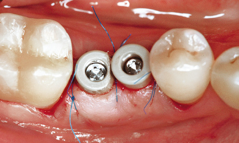
Fig 2-2e The healing abutments have been screwed into place and the distal abutment has been filed to shape.
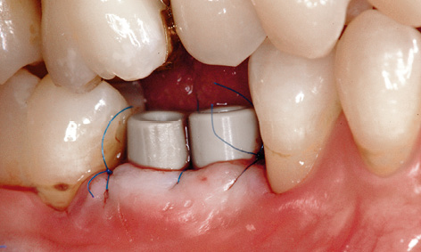
Fig 2-2f Sufficient distance from the opposing jaw has been maintained.
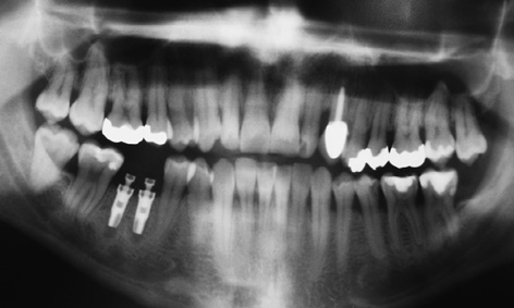
Fig 2-2g Postoperative radiograph.
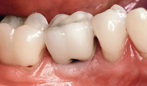
Fig 2-2h Screw-retained metal-ceramic crown on the customized abutments with cleaning channel.
Attention: To assure long-term success following implant loading, it is very important for the implants, the prosthetic crown and the neighboring teeth to be kept clean at all times. For optimal hygiene of the implant-supported restoration, the crown has been fabricated with a cleaning channel to admit interdental brushes (see Fig 2-2h).
Treatment course
- Implant placement (2004)
- 5 months to impression taking and fabrication
Treatment
|
Surgery: |
Dr Christoph T. Sliwowski |
|
Prosthetics: |
Dr Uwe Hildebrand |
|
Dental technology: |
Ute Olbers |
Typical treatment course
Replacement of a molar with an implant with vertical mucosal distraction
Baseline situation
This patient was missing teeth 36 and 46 from her mandible. Since teeth 35 and 37 needed crowning, the plan was to use a conventional metal-ceramic dental bridge on the left side. One single-tooth crown on an implant has been planned on the right side. Tooth 47 had wandered in the mesial direction, so that a single implant fitted into the gap exactly (Fig 2-3a). The tooth had several amalgam fillings and was to be crowned at the same time as the implant loading. Both vertical (Fig 2-3a) and horizontal atrophy of the residual ridge (Fig 2-3b) were clearly apparent several years after the loss of tooth 46.
Diagnostic tools
- Clinical examination
- Panoramic radiograph, CBCT
- SimPlant planning
- Dental cast analysis
Treatment plan
1.Extraction and immediate implant placement with augmentation
2.Exposure and definitive prosthetic loading
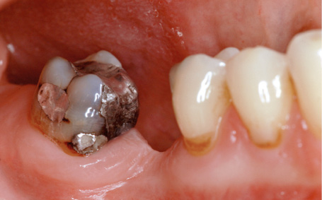
Fig 2-3a The gap left by the loss of tooth 46.
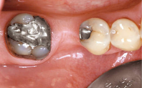
Fig 2-3b Horizontal atrophy.
Implant placement and mucosal distraction
An arcuate incision was made on the lingual side, to allow the keratinized gingiva to be transplanted in the buccal direction (Fig 2-3c). Since transmucosal healing was planned, the implant was inserted 1 to 2 mm supracrestally (Fig 2-3d). A 5-mm-high PEEK healing abutment was fitted onto the implant (Fig 2-3e) and the harvested bone chips were layered onto the buccal side for the augmentation (Fig 2-3f). For financial reasons, the augmentation was performed without the use of synthetic materials, limiting its volume. The flap was repositioned and stabilized in the interproximal spaces with two 6-0 Mopylen (Resorba) sutures (Fig 2-3g).
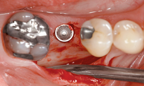
Fig 2-3c Arcuate incision.
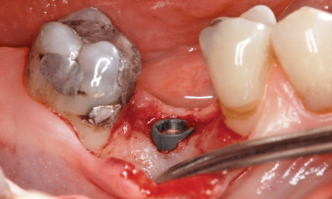
Fig 2-3d The implant inserted supracrestally.
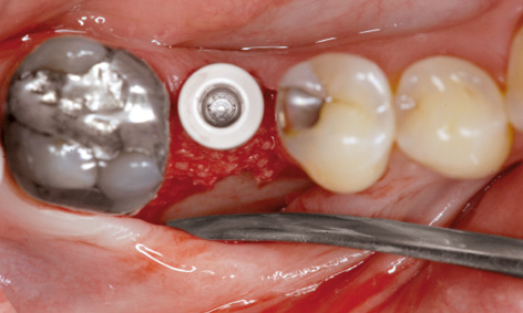
Fig 2-3e The abutment has been screwed into place.
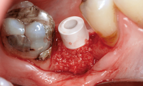
Fig 2-3f Augmentation.
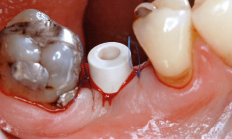
Fig 2-3g Suturing.
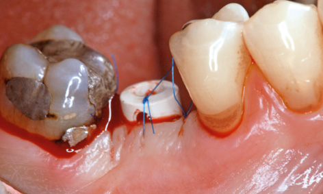
Fig 2-3h Vertical mucosal distraction.
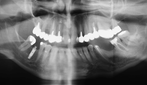
Fig 2-3i Postoperative panoramic radiograph.
Despite transplantation of the keratinized gingiva, the contour of the residual ridge was not optimal, but could be improved slightly with vertical mucosal distraction. A small perforation was made in the plastic of the coronal part of the healing abutment, and the mucoperiosteal flap lifted up and fixed into this position with a suture (Fig 2-3h). The postoperative panoramic radiograph shows the implant in relation to the nerve and the neighboring teeth (Fig 2-3i).
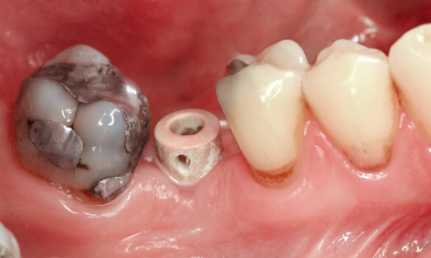
Fig 2-3j Clinical situation before taking the impression.
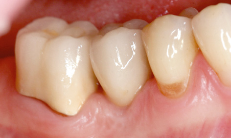
Fig 2-3k Incorporated metal-ceramic crowns on the implant and on tooth 47.
Prosthetic loading
Four months after the implant placement, the soft tissue situation had stabilized; the implant had healed and could be loaded with a crown (Fig 2-3j). While the gingiva had receded somewhat, its contour was still more favorable than directly after implant placement (compare Figs 2-3g and 2-3j). This improvement could be ascribed to the vertical mucosal distraction (Fig 2-3j). The implant and tooth 47 were loaded with metal-ceramic crowns (Fig 2-3k). The patient was very satisfied with both the final result and the lower costs, and the reasonable extent of the treatment.
Treatment course
- Implant placement, augmentation and mucosal distraction (2006)
- 4 months to the prosthetic loading
Treatment
|
Surgery: |
Dr Christoph T. Sliwowski |
|
Prosthetics: |
Dr Roland Althoff |
|
Dental technology: |
Angela Althoff |
Atypical treatment course – problematic baseline situation
Replacement of a molar with one implant in a large gap
Baseline situation
After losing tooth 46, this young woman had been fitted with a fixed bridge at another practice a few years previously. The dental bridge was anchored with a full crown on tooth 45 and an inlay on tooth 47 (Fig 2-4a). Unfortunately, it repeatedly came loose, so that the patient made specific inquiries about an implant restoration.
Before the implant analysis, a provisional restoration was made out of plastic, to rule out any artifacts produced by the metal crowns during the tomography (Fig 2-4b). Volume tomography (CBCT) was performed with the NewTom scanner (QR) and the resultant data transferred to the SimPlant planning program in Digital Imaging and Communications in Medicine (DICOM) format. A Neoss implant, 15-mm long and 4 mm in diameter, was planned for the replacement of tooth 46, and virtually inserted on screen (Fig 2-4c). The implant was inserted approx 2 mm supracrestally, but the distance to the nerve, also 2 mm, was maintained. The planned position of the implant is best visualized on the semi-transparent 3D reconstruction with the nerve also visible (Fig 2-4d).
Diagnostic tools
- Clinical examination
- Panoramic radiograph, CBCT
- SimPlant planning
- Dental cast analysis
Treatment plan
1.Implant placement with augmentation
2.Definitive prosthetic loading
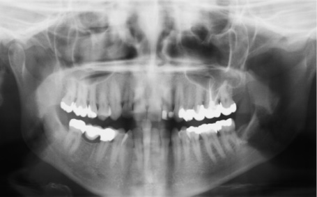
Fig 2-4a Panoramic radiograph of the baseline situation.
Fig 2-4b Plastic provisional restoration for the CBCT scan.
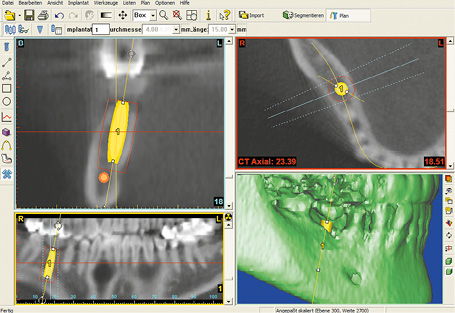
Fig 2-4c Implant planning in the SimPlant program.
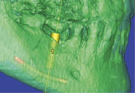
Fig 2-4d Semi-transparent 3D reconstruction.
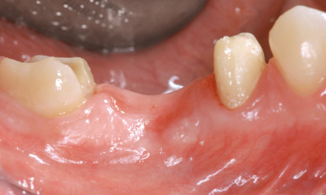
Fig 2-4e Vertical and horizontal residual ridge atrophy.
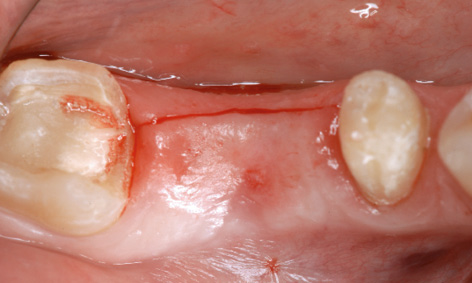
Fig 2-4f Lingual section on the residual ridge.
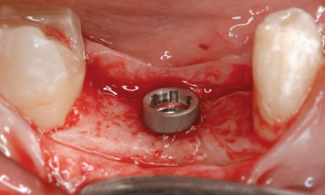
Fig 2-4g Implant inserted approx 2 mm supracrestally.
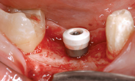
Fig 2-4h Short PEEK healing abutment screwed into place.
Implant placement with augmentation
Before implant placement, the right inferior alveolar nerve was numbed using block anesthesia and the provisional partial denture was removed (Fig 2-4e). This made the vertical and horizontal bone defect more clearly apparent. For the planned augmentation and condensation of the gingiva, the incision was made lingually, but still on the residual ridge (Fig 2-4f). Following mobilization of the buccal mucoperiosteal flap (with no releasing incisions), the implant was inserted approximately 2 mm supracrestally, as planned (Fig 2-4g). To spare the patient a second procedure, ie, implant exposure, a 2.7-mm-long PEEK healing abutment was screwed directly onto the implant (Fig 2-4h).
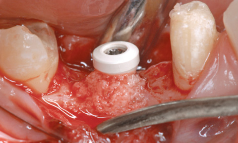
Fig 2-4i Augmentation with the bone chips.
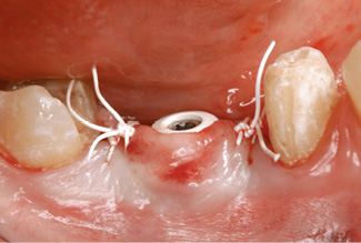
Fig 2-4j Suturing.
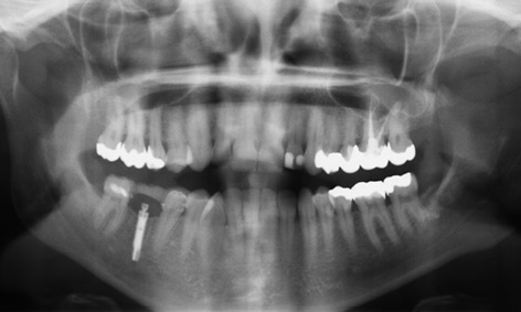
Fig 2-4k Postoperative panoramic radiograph.
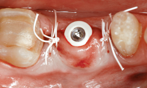
Fig 2-4l Buccal displacement of the fixed gingiva.
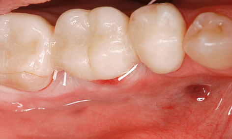
Fig 2-4m Buccal shaping of the residual ridge.
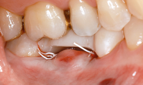
Fig 2-4n Provisional restoration cut away at the base, reliably protecting the implant from masticatory stress.
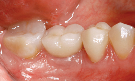
Fig 2-4o Definitive implant crown after 5 years in functional use.
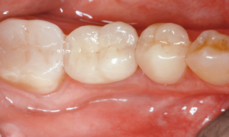
Fig 2-4p Buccal shaping of the residual ridge.
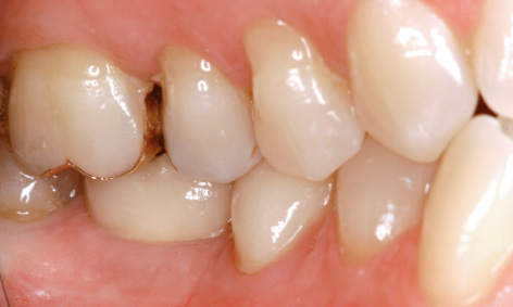
Fig 2-4q Harmonious appearance of the prosthetic reconstructions.
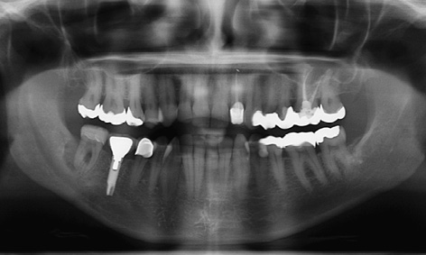
Fig 2-4r Panoramic radiograph after 5 years with the incidental finding on tooth 47.
For the augmentation, the cortical bone layer around the implant was perforated in several places to encourage revascularization, and bone chips collected in the filter were layered onto the buccal side of the residual ridge (Fig 2-4i). For larger augmentations, it would also have been possible to use a regenerative bone substitute and a membrane, but this would have meant greater financial cost.
The buccal flap was then repositioned and fixed around the healing abutment with Gore-Tex sutures (W. L. Gore and Associates) (Fig 2-4j). The postoperative panoramic radiograph shows the position of the implant relative to the nerve and the neighboring teeth (Fig 2-4k). The augmentation has had a positive effect not only vertically, but also in the horizontal plane (Fig 2-4l). The improved buccal contour of the residual ridge can be assessed postoperatively once the provisional bridge has been fitted (Fig 2-4 m). If the same provisional restoration is to be reused, sufficient place needs to be made for the protruding healing abutment. The reshaped provisional protects the implant not only from masticatory stresses, but also from possible pressure from the tongue, which can sometimes even be dangerous (Fig 2-4n).
Four months after implant placement, both the implant and the neighboring teeth were fitted with a prosthetic restoration. The final photographs show the clinical situation with apparently healthy gums after 5 years (Fig 2-4o). While the buccal bulge (jugum alveolare) over the implant is smaller than with some teeth, it is still more marked than before implant placement (compare Figs 2-4f and 2-4p). The prosthetic restoration has been harmoniously incorporated into the overall appearance of the mouth (Fig 2-4q). However, the panoramic radiograph after 5 years shows an incidental finding on tooth 47 (Fig 2-4r). According to the radiograph, implant 46 has undergone good osseous integration, but tooth 47 shows a distal zone of radiolucency, probably a periodontal-endodontic lesion, which requires urgent treatment although the patient has no symptoms and has not noticed the inflammation at all.
Treatment course
- Implant placement, augmentation and mucosal distraction (2007)
- 4 months to prosthetic loading
Treatment
|
Surgery: |
Dr Christoph T. Sliwowski |
|
Prosthetics: |
Dr Roland Althoff |
|
Dental technology: |
Angela Althoff |
Problems and complications
Fracture of a non-WP implant
Baseline situation
A 16-mm-long, non-WP Straumann implant replacing molar 46 had been inserted and loaded with a crown at another center. In this patient’s history, he had reported repeated loosening of the abutment screw. Finally, after being in place for about 1 year, the implant had fractured below bone level (Figs 2-5a and 2-5b), necessitating removal of the implant. The maximum utilization of the vertical bone supply through the use of the 16-mm implant complicated the removal considerably. Implant removal requires full reaming of the bone around the implant, which extends to just short of the nerve, with a risk of damaging the latter.
Diagnostic tools
- Clinical examination
- Panoramic radiograph
- Dental cast analysis
Treatment plan
1.Explantation of the broken implant and augmentation of the bone defect
2.Insertion of two implants
3.Secondary exposure
4.Cement-retained metal-ceramic crown on two implants and customized abutments
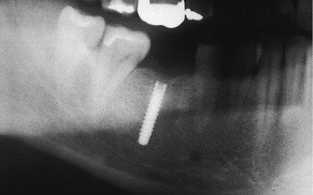
Fig 2-5a Fractured Straumann implant.
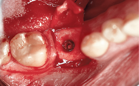
Fig 2-5b Fracture site below bone level.
Attention: The use of a standardized trephine, as small in diameter as possible, minimizes the resultant bone defect. For guidance when using a trephine, it can be helpful to screw an impression post screw onto the implant as a direction indicator. In this case, however, this was no longer possible because the implant thread had fractured completely.
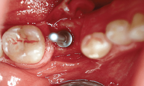
Fig 2-5c Trephine put into place.
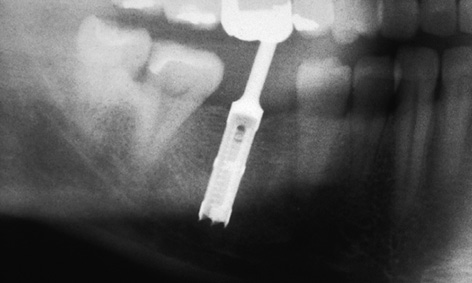
Fig 2-5d Radiograph showing the inserted trephine.

Fig 2-5e Oversized crown relative to the diameter of the implant.
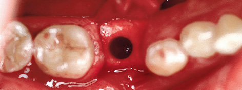
Fig 2-5f Bone defect following explantation.
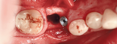
Fig 2-5g The inserted mesial implant.
Implant removal and augmentation
Following a buccal incision, the dissected flap was fixed to the premolar in the third quadrant with a single suture to give a clear view of the operation site. The drilling depth was initially determined from the preoperative measurements taken from the radiograph. An intraoperative radiograph with the trephine inserted provided an additional check of the drilling depth (Figs 2-5c and 2-5d). Once the bone around the implant had been fully reamed away, the implant was removed by careful luxation with a lever.
The fractured elements of the implant, with the crown structure screwed on via an abutment, suggest a fatigue fracture of the inadequately sized implant (Fig 2-5e). Based on his experience so far, the patient placed no trust in a single-tooth implant and wanted a restoration loaded on two implants to be on the safe side. However, the resultant bone defect prevented immediate implant placement in this area (Fig 2-5f). Initially, therefore, a single RP implant was inserted mesially of the defect (Fig 2-5g) and the defect augmented with a bone substitute (Bio-Oss; Geistlich).
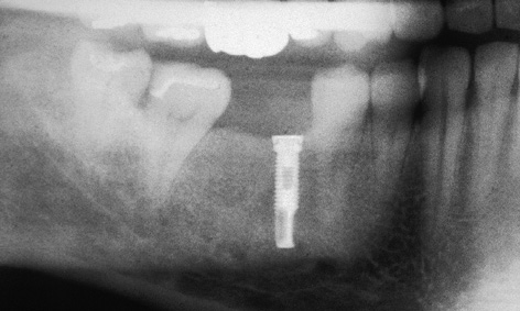
Fig 2-5h Preoperative radiograph.
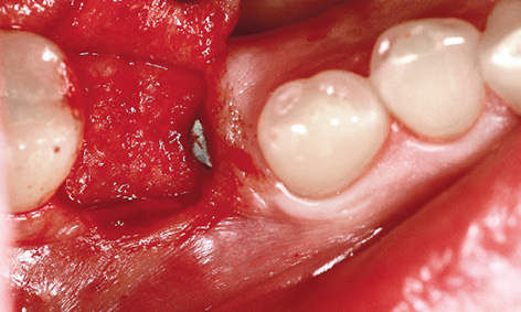
Fig 2-5i Regenerated bone defect.
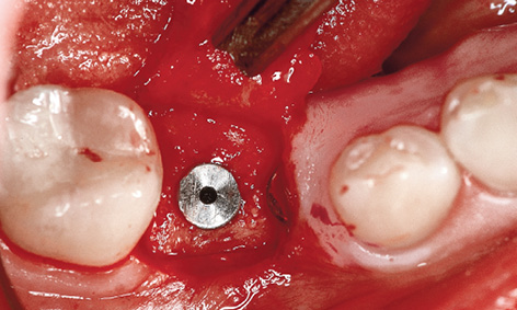
Fig 2-5j Inserted distal Brånemark System implant.
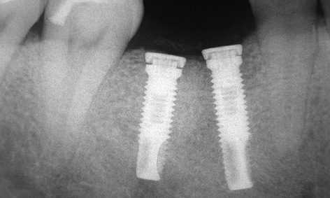
Fig 2-5k Postoperative radiograph after implant placement.
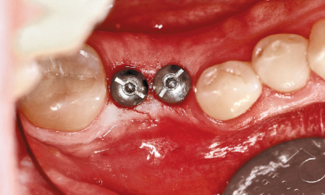
Fig 2-5l Exposed implants.
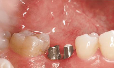
Fig 2-5m Customized abutments.
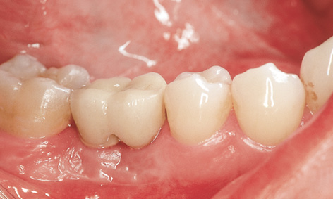
Fig 2-5n Metal-ceramic crown after 7 years in functional use.
Delayed implant placement
The radiograph and clinical inspection after 6 months already showed clear reossification in the augmentation area (Fig 2-5h and 2-5i), allowing a second Brånemark System (Nobel Biocare) implant to be inserted (Fig 2-5j). The positioning of the new distal implant relative to the neighboring tooth and the mesial implant is clearly apparent on the radiograph (Fig 2-5k).
Exposure and prosthetic loading
The implants were exposed after a further 6 months (Fig 2-5l). They were then loaded with a prosthesis consisting of an interlocked crown on two customized abutments (Fig 2-5m). The clinical situation 7 years after the restoration was incorporated shows a stable peri-implant situation with no inflammation (Fig 2-5n).
Treatment course
- Explantation, augmentation and partial implant placement (1998)
- 6 months to the delayed implant placement
- 6 months to exposure
- 3 weeks to impression taking and fabrication
Treatment
|
Surgery: |
Dr Christoph T. Sliwowski |
|
Prosthetics: |
Dr Uwe Hildebrand |
|
Dental technology: |
Fernando Abrantes |
Note
Iatrogenic complication with nerve involvement
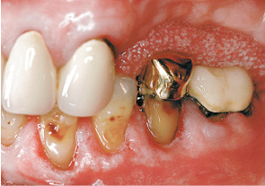
Fig 2-6a Elongation of tooth 35.
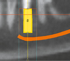
Fig 2-6b SimPlant planning.
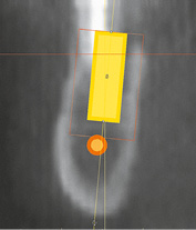
Fig 2-6c Planned implant in cross-sectional view.
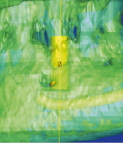
Fig 2-6d Semi-transparent 3D reconstruction.
Fig 2-6e Implant placement directly after the extraction.
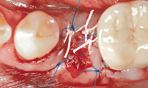
Fig 2-6f Wound suturing.
In this patient, tooth 35 became elongated due to missing teeth in the maxilla (Fig 2-6a). The width of the residual ridge had been well maintained thanks to the presence of tooth 35, allowing optimal placement of the implant in the buccolingual dimension. Since the tooth was no longer securely anchored, as can be seen in the radiograph, atraumatic extraction appeared possible.
Analysis and virtual implant planning with the SimPlant planning program indicated sufficient bone availability for the insertion of a 13-mm-long implant, with a 4.5-mm diameter, maintaining the required safe distance of 2 mm to the nerve (Fig 2-6b). The distance to the nerve also appeared sufficient in the cross section of Fig 2-6c. Only the 3D reconstruction raised doubts as to the height of the preserved buccal lamella (Fig 2-6d). Exactly as in the planning procedure, the intended implant was inserted into the socket directly after the extraction (Fig 2-6e). Since implant placement followed on directly from extraction, there was no clearly defined bone height on the buccal side that would have allowed the virtual planning to be applied to the operation site. This deficiency is the most likely cause of the complication that was to follow. After the insertion, the buccal bone defect was filled with the harvested bone chips. The mucoperiosteal flap was mobilized sufficiently to allow saliva-proof wound closure with Gore-Tex and Surgipro (Covidien) sutures, without the use of a membrane (Fig 2-6f). A CBCT scan was performed for a postoperative check. The panoramic view suggested that the implant was placed deeper than planned (Fig 2-6g). This complication becomes even clearer in the cross-sectional views (Fig 2-6h). Marking the nerve in red shows the extent and site of the implant’s collision with the nerve particularly well (Fig 2-6i). To avoid permanent nerve damage, the nerve needed to be decompressed as quickly as possible.
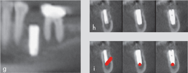
Fig 2-6g to 2-6i Panoramic view (g). Cross section (h). Collision of the implant with the nerve (i).
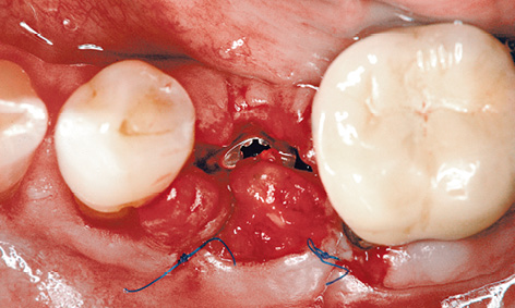
Fig 2-6j Partially reopened gum.
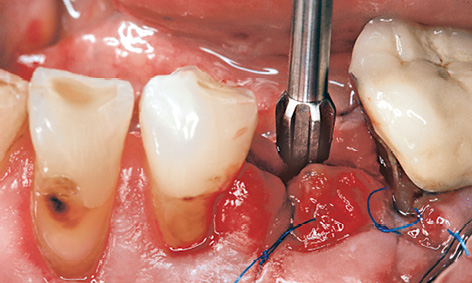
Fig 2-6k Unscrewing the implant by two turns.
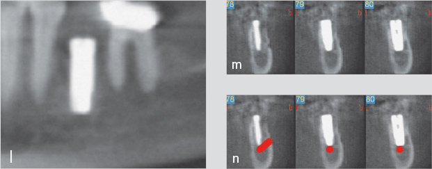
Fig 2-6l to 2-6n Improved implant position (l). Cross sections (m and n).
The next day (the patient having confirmed persistent numbing), the gum was partially reopened (Fig 2-6j) and the implant unscrewed by two turns (Fig 2-6k). Another CBCT scan was taken to check the situation and reconstructed with a slice thickness of 0.3 mm for maximum precision. The panoramic section now shows the more favorable location of the implant directly over the mental foramen (Fig 2-6l), and the cross sections, with and without the nerve marked in red, confirm that the implant has disappeared from the canal (Figs 2-6m and 2-6n).
In most similar cases, feeling returns to the lower lip after a few months at the latest, although the damage may remain irreversible and leave the patient with an unpleasant numbness in the lower lip for life. In this patient, sensitivity improved after only 3 weeks, with full sensation returning after 4 months.
Immediate loading
Immediate provisional loading of a definitive implant
This treatment course follows on from the 3D diagnostic investigations on page 40.
Baseline situation
In this 28-year-old woman, the persistent primary tooth 85 has taken on dark discoloration and is no longer preservable (Fig 2-7a). However, preserving the primary tooth until the implant treatment counteracts atrophy, ensuring optimum preservation of both the height and width of the alveolar process at the time of implant placement. The implant was to be inserted directly after the extraction and loaded with a provisional crown.
Diagnostic tools
- Clinical examination
- CBCT
- SimPlant planning
- Dental cast analysis
Treatment plan
1.Extraction of the primary tooth and immediate placement of a WP implant. Direct incorporation of a provisional crown after the implant placement
2.Prosthesis in the form of a cement-retained metal-ceramic crown
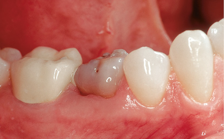
Fig 2-7a Remaining primary tooth 85.
Laboratory technique
In the cast, tooth 85, which needed extracting, was erased and an implant or abutment analog in accordance with the CBCT-based 3D radiologic investigations (see diagnostic investigations, page 40) was inserted into the model (Fig 2-7b). The bone supply and the width of the gap permitted placement of a WP implant 5 mm in diameter. A CeraOne abutment with plastic cap was prepared in the laboratory to take the immediate provisional prosthesis (Fig 2-7c) and a plastic crown was prepared in the form of an eggshell provisional (Fig 2-7d). The provisional crown was to be polymerized onto the plastic cap following insertion of the implant.
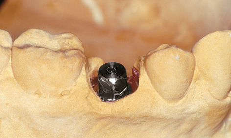
Fig 2-7b CeraOne model abutment incorporated into the plaster cast.
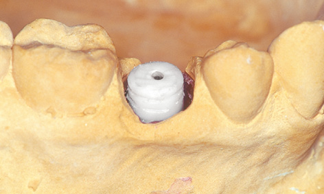
Fig 2-7c Shortened plastic cap.
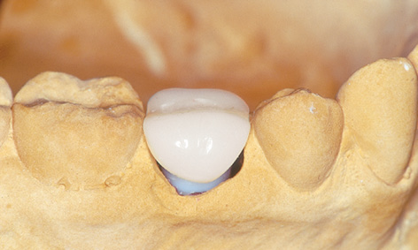
Fig 2-7d Provisional crown.
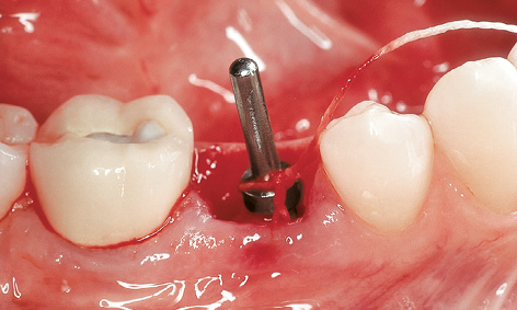
Fig 2-7e Checking the position and alignment of the implant bed.
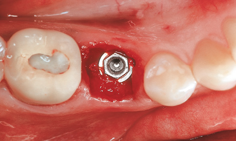
Fig 2-7f Inserted WP implant.
Extraction, implant placement and provisional restoration
The primary tooth was extracted immediately before implant placement. After the initial preparation with the 2- and 3-mm drills, the position and alignment of the implant bed were checked using a direction indicator (Fig 2-7e).
The implant bed was then prepared to a further diameter of 4.3 mm. Once the process was completed with a thread cutter, the WP implant (diameter 5 mm) was inserted due to the dense bone structure at the site (Fig 2-7f).
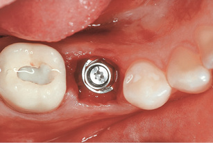
Fig 2-7g CeraOne abutment screwed into place.
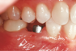
Fig 2-7h Adequate occlusal distance.
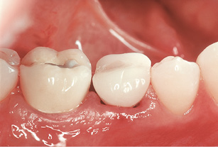
Fig 2-7i Inserted provisional crown.
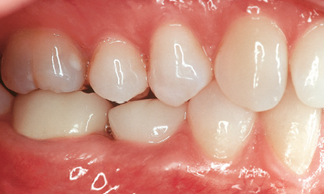
Fig 2-7j Provisional crown out of occlusion.
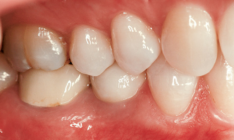
Fig 2-7k Metal-ceramic crown after 3 in functional use.
The CeraOne abutment was screwed into place (Fig 2-7g). For the provisional crown, it was important to maintain an adequate occlusal distance (at least 2 mm) to the antagonist tooth (Fig 2-7h). The prepared eggshell provisional was filled with quick-hardening, autopolymerizing plastic and incorporated. After shaping, the provisional crown was cemented into place with TempBond (Kerr) (Fig 2-7i). The final photographs show the clinical situation 5 months after implant placement and 3 years after the incorporation of the definitive prosthetic restoration (Fig 2-7j and 2-7k).
Treatment course
- Implant placement and immediate loading (2002)
- 5 months to impression taking and fabrication
Treatment
|
Surgery and provisional crown: |
Dr Christoph T. Sliwowski |
|
Prosthetics: |
Dr Uwe Hildebrandt |
|
Dental technology: |
Ivonne Lewik |
Multi-tooth gap and free-end situation
Patients missing more than one tooth in the posterior mandible present with either a multi-tooth gap between teeth or a free-end situation, the second being far more common. Since treatment for both indications is similar, the focus here will be placed on the free-end situation. In the case of a free-end situation – in contrast to a multi-tooth gap between teeth – the only fixed prosthetic restoration option without the use of implants is a cantilever fixed partial denture. The number of implants depends on the size of the gap, with one implant recommended for each tooth that needs to be replaced. However, a minimum distance of 3 mm needs to be maintained between implants. In a free-end situation, at least two implants, but preferably three or four, are recommended. A superstructure supported on three or more implants shows far fewer complications than one loaded onto only two implants. These include both biologic complications (bone loss if the implants are overloaded) and mechanical complications (loosening or fracture of the retaining screws or even implant fractures).
Diagnosis and planning in the case of a large multi-tooth gap or free-end situation need to proceed with at least as much care as with single-tooth implant placement in the posterior mandible, because each individual implant may lead to damage to the inferior alveolar nerve. Implantology associations recommend a diagnostic measuring radiograph (panoramic image) with a template that contains incorporated measurement devices as the minimum imaging procedure. Its disadvantage is that it does not provide the most important information, namely the width of the residual ridge. A CBCT or CT scan is advisable in most cases not only for forensic but also practical reasons, due to the risk of nerve injury.
Typical treatment course
Two-session approach with augmentation
Baseline situation
A 70-year-old man wished to have a fixed prosthetic restoration on both sides of the mandible. Dental treatment on the right side had already been completed, while tooth 37 remained to be extracted on the left side (Fig 2-8a).
Diagnostic tools
- Clinical examination
- Panoramic radiograph
- CBCT
- SimPlant planning
- Dental cast analysis
Treatment plan
1.Extraction and immediate implant placement or delayed immediate implant placement with augmentation
2.Exposure and definitive prosthetic loading
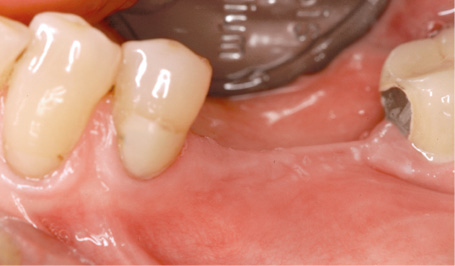
Fig 2-8a Tooth 37 before the extraction.
Stay updated, free dental videos. Join our Telegram channel
VIDEdental - Online dental courses


