CHAPTER 5 Major and Minor Connectors
Components of a typical removable partial denture are illustrated in Figure 5-1.
Role of Major Connectors in Control of Prosthesis Movement
Location
Major connectors should be designed and located with the following guidelines in mind:
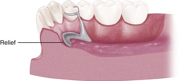
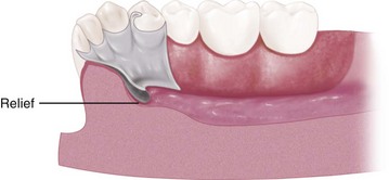
Appropriate relief beneath the major connector avoids the need for its adjustment after tissue damage has occurred. In addition to being time consuming, grinding to provide relief from impingement may seriously weaken the major connector, which can result in flexibility or possibly fracture. Major connectors should be carefully designed for proper shape, thickness, and location. Alteration of these dimensions by grinding can only be detrimental. Relief is covered at the end of this chapter and is expanded in Chapter 11.
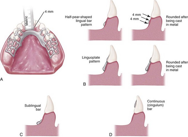
Margins of major connectors adjacent to gingival tissue should be located far enough from the tissue to avoid any possible impingement. To accomplish this, it is recommended that the superior border of a lingual bar connector be located a minimum of 4 mm below the gingival margin(s) (Figure 5-2). At the inferior border of the lingual bar connector, the limiting factor is the height of the moving tissue in the floor of the mouth. Because the connector must have sufficient width and bulk to provide rigidity, a linguoplate is commonly used when space is insufficient for a lingual bar.
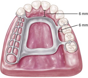
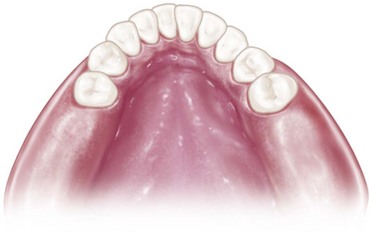
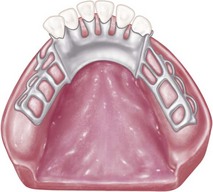
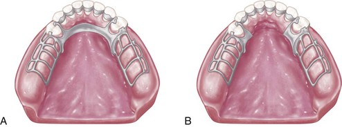
In the maxillary arch, because no moving tissue is present in the palate as in the floor of the mouth, the borders of the major connector may be placed well away from gingival tissue. Structurally, the tissue covering the palate is well suited for placement of the connector because of the presence of firm submucosal connective tissue and an adequate, deep blood supply. However, when soft tissue covering the midline of the palate is less displaceable than the tissue covering the residual ridge, varying amounts of relief under the connectors must be provided to avoid impingement of tissue. The amount of relief required is directly proportional to the difference in displaceability of the tissue covering the midline of the palate and the tissue covering the residual ridges. The gingival tissue, on the other hand, must have an unrestricted superficial blood supply to remain healthy. To accomplish this, it is recommended that the borders of the palatal connector be placed a minimum of 6 mm away from and parallel to the gingival margins. Minor connectors that must cross gingival tissue should do so abruptly, joining the major connector at nearly a right angle (Figure 5-3). In this way, maximum freedom is ensured for gingival tissue.
Characteristics of major connectors that contribute to the maintenance of health of the oral environment and the well-being of the patient may be listed as shown in Box 5-1.
Mandibular Major Connectors
The six types of mandibular major connectors include the following:
Lingual Bar
The basic form of a mandibular major connector is a half-pear shape, located above moving tissue but as far below the gingival tissue as possible. It is usually made of reinforced, 6-gauge, half-pear–shaped wax or a similar plastic pattern (Figure 5-5).
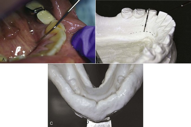
At least two clinically acceptable methods may be used to determine the relative height of the floor of the mouth and locate the inferior border of a lingual mandibular major connector. The first method is to measure the height of the floor of the mouth in relation to the lingual gingival margins of adjacent teeth with a periodontal probe (Figure 5-6). When these measurements are taken, the tip of the patient’s tongue should just lightly touch the vermilion border of the upper lip. Recording of these measurements permits their transfer to both diagnostic and master casts, thus ensuring a rather advantageous location of the inferior border of the major connector. The second method is to use an individualized impression tray for which lingual borders are 3 mm short of the elevated floor of the mouth, and then to use an impression material that will permit the impression to be accurately molded as the patient licks the lips. The inferior border of the planned major connector can then be located at the height of the lingual sulcus of the cast resulting from such an impression. Of the two methods, we have found measuring the height of the floor of the mouth to be less variable and more clinically acceptable.
Linguoplate
If the rectangular space is bounded by the lingual bar, the anterior tooth contacts, and the cingula, and the bordering minor connectors are filled in, a linguoplate results (Figure 5-7).
A linguoplate should be made as thin as is technically feasible and should be contoured to follow the contours of the teeth and the embrasures (Figure 5-8). The patient should be aware of as little added bulk and as few altered contours as possible. The upper border should follow the natural curvature of the supracingular surfaces of the teeth and should not be located above the middle third of the lingual surface, except to cover interproximal spaces to the contact points. The half-pear shape of a lingual bar should still form the inferior border that provides the greatest bulk and rigidity. All gingival crevices and deep embrasures must be blocked out parallel to the path of placement to avoid gingival irritation and any wedging effect between the teeth. In many instances, judicious recontouring of the lingual proximal surfaces of overlapped anterior teeth permits closer adaptation of the linguoplate major connector, eliminating otherwise deep interproximal embrasures to be covered (Figure 5-9).
The same reasons for use of a linguoplate anteriorly apply to its use elsewhere in the mandibular arch. If a lingual bar alone is to be used anteriorly, there is no reason to add an apron elsewhere. However, when auxiliary splinting is used for stabilization of the remaining teeth or for horizontal stabilization of the prosthesis, or for both, small rectangular spaces sometimes remain. Tissue response to such small spaces is better when they are bridged with an apron than when they are left open. Generally, the apron is used to avoid gingival irritation or entrapment of food debris or to cover generously relieved areas that would be irritating to the tongue (Figure 5-10).
Sometimes a dentist is faced with a clinical situation wherein a linguoplate is indicated as the major connector of choice even though the anterior teeth are quite spaced and the patient strenuously objects to metal showing through the spaces. The linguoplate can then be constructed so that the metal will not appreciably show through the spaced anterior teeth (Figure 5-11). The rigidity of the major connector is not greatly altered. However, such a design may be as much of a food trap as the continuous bar type of major connector.
Design of Mandibular Major Connectors
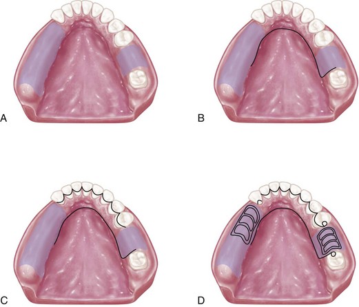
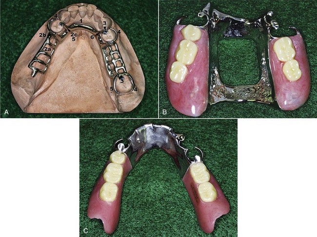
Figure 5-12 Sequence of design considerations for a mandibular major connector. A, Diagnostic cast with basal seat areas outlined. B, Inferior border of the major connector is outlined. Location of the inferior border was determined as suggested in Figure 5-6 and extends to the mesial of the mandibular right molar. C, Superior border of the major connector is outlined. Limited space for the lingual bar requires use of the linguoplate major connector. Linguoplate requires that rest seats be used on canines and the first premolar for positive support. D, Rest seat areas on the posterior teeth are outlined, and minor connectors for retention of resin denture bases are sketched.
Cingulum Bar (Continuous Bar)
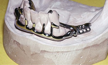
When a linguoplate is the major connector of choice, but the axial alignment of the anterior teeth is such that excessive blockout of interproximal undercuts must be made, a cingulum bar may be considered. A cingulum bar located on or slightly above the cingula of the anterior teeth may be added to the lingual bar or can be used independently (Figure 5-13). In addition, when wide diastemata exist between the lower anterior teeth, a continuous bar retainer may be more esthetically acceptable than a linguoplate.
Labial Bar
Fortunately, in only a few situations does extreme lingual inclination of the remaining lower premolar and incisor teeth prevent the use of a lingual bar major connector. With the use of conservative mouth preparations in the form of recontouring and blockout, a lingual major connector can almost always be used. Lingually inclined teeth sometimes may have to be reshaped by means of crowns. Although the use of a labial major connector may be necessary in rare instances, this should be avoided by resorting to necessary mouth preparations rather than by accepting a condition that is otherwise correctable (Figure 5-14). The same applies to the use of a labial bar when a mandibular torus interferes with placement of a lingual bar. Unless surgery is definitely contraindicated, interfering mandibular tori should be removed so that the use of a labial bar connector may be avoided.
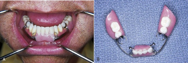
A modification to the linguoplate is the hinged continuous labial bar. This concept is incorporated in the Swing-Lock* design, which consists of a labial or buccal bar that is connected to the major connector by a hinge at one end and a latch at the other end (Figure 5-15).
Stay updated, free dental videos. Join our Telegram channel
VIDEdental - Online dental courses


