Chapter 3
What is ultrasonic instrumentation?
CHAPTER OBJECTIVES
On completion of this chapter, the student will be able to:
- Differentiate between magnetostrictive and piezoelectric ultrasonic transduction.
- Define the mechanisms of action by which ultrasonic instruments remove deposits from the tooth surface.
- Explain the relationship of key operational variables to the acoustic power produced by the ultrasonic scaling unit.
- Adjust the operational variables as necessary in order to operate the ultrasonic scaling unit at a level of acoustic power appropriate for the treatment objective.
As presented in Chapter 1, the objective of periodontal debridement is to reduce periodontal pathogens and promote periodontal health by disrupting and removing deposits, ranging from biofilm to calculus, without over-instrumentation of the root surface. Hand scaling instruments (sickles, curettes, files, hoes, and chisels) remove/disrupt the deposits by manually stroking a bladed cutting edge across the tooth surface to mechanically break the bond between the deposit and the tooth (Lea and Walmsley, 2009). Ultrasonic scaling instruments oscillate (move forward and backward) a typically blunt metal tip at a high-frequency producing mechanical vibratory, cavitational and acoustic microstreaming forces that remove/disrupt the deposits. (Walmsley et al., 1984; Khambay and Walmsley, 1999).
Sound is a form of energy produced by vibrations. Humans can hear sound at frequencies up to 20,000 Hz or 20 kHz. The term ultrasonic applies to sound (or acoustic) energy having a frequency greater than 20 kHz, above the range audible to the human ear (Walmsley, 1989). Ultrasound is used in many different fields, typically to penetrate a medium and measure the reflection signature (e.g., sonography used in obstetrics) or to supply focused energy (e.g., ultrasonic cleaning of jewelry) (Figure 3.1).
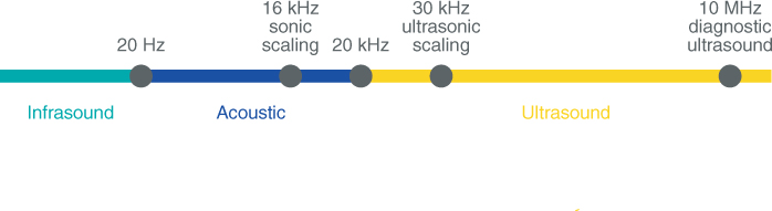
Figure 3.1 Range of sound frequencies. Frequencies >20 kHz are ultrasonic
Ultrasonic dental instruments convert electrical current into high-frequency (25–30 kHz) mechanical vibrations (Lea and Walmsley, 2009). The conversion is attained by either a magnetostrictive or piezoelectric transducer.
ULTRASONIC TRANSDUCTION
Magnetostriction
Magnetostriction is defined as the changing of a material’s physical dimensions in response to changing its magnetization. In other words, a magnetostrictive material will change shape when it is subjected to a magnetic field (Laird and Walmsley, 1991). Examples of magnetostrictive materials are iron, nickel, nickel alloys, and cobalt.
In ultrasonic dental devices, magnetostriction is attained by applying an alternating electromagnetic field to a stack of nickel strips. In response to the magnetization, the nickel stack elongates, then contracts along its length (i.e., changes dimensions) producing longitudinal vibrations (Oda et al., 2004) (Figure 3.2). These vibrations travel from the stack through a connecting body to a tip, resulting in high-frequency oscillation of the tip (Figure 3.3).
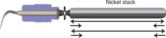
Figure 3.2 Diagram of a magnetostrictive insert. Application of an electromagnetic field to the stack of nickel strips results in magnetostriction – elongation then contraction – of the nickel stack along its length, producing longitudinal vibrations
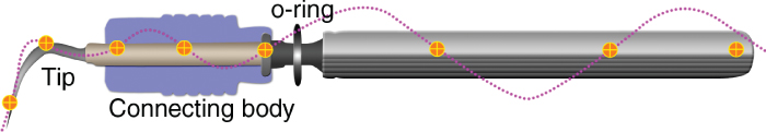
Figure 3.3 Longitudinal vibrations travel from the nickel stack through a connecting body to the tip of the insert. The crosshairs denote points of no vibration or movement, referred to as nodal points or antinodes
The electromagnetic energy produced by magnetostrictive scaling units has been a topic of controversy with regard to any potential interaction with cardiac pacemakers. This issue is fully addressed in Chapter 5.
The components characteristic of magnetostrictive scaling units are listed in Table 3.1 and illustrated by Figures 3.4–3.8.
Table 3.1 Components of magnetostrictive ultrasonic units
| Component | Description | |
Insert
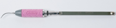 Figure 3.4 A magnetostrictive insert |
Composed of a stack of thin nickel strips soldered together at the ends and attached by a connecting body to a tip | |
Handpiece
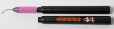 Figure 3.5 The handpiece of a magnetostrictive unit contains a spiral of copper wire (visible in the lower, cut-out handpiece), which surrounds the stack once the insert is seated in the handpiece |
Holds the insert to surround the nickel stack in a spiral of copper wire which generates a magnetic field upon application of electrical current, resulting in magnetostriction of the stack | |
| Base unit | ||
| Houses controls which regulate power level and water flow; provides connection between foot switch and handpiece | ||
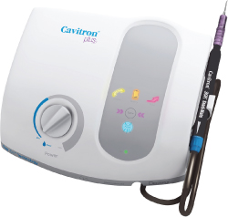 Figure 3.6 Cavitron® plus magnetostrictive scaler (Image courtesy of Dentsply Professional)
|
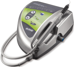 Figure 3.7 SWERV® magnetostrictive scaler (Image courtesy of Hu-Friedy Mfg Co., LLC, Chicago IL, USA)
|
 Figure 3.8 Integra™ magnetostrictive scaler (Image courtesy of Parkell, Inc).
|
| Foot switch | When engaged, sends electrical current through base unit to the handpiece, activating movement of the tip | |
Piezoelectricity
Crystalline structures, such as quartz and certain ceramics, which undergo dimensional changes when subjected to an electrical field are said to be piezoelectric (Laird and Walmsley, 1991).
In ultrasonic dental devices with a piezoelectric transducer, an alternating electrical current is applied across a ceramic or quartz disk (Figure 3.9). In response to the alternating application of current, the crystalline structure alternatingly expands then contracts, producing vibrations that result in high-frequency oscillation of the tip (Laird and Walmsley, 1991) (Figure 3.10).
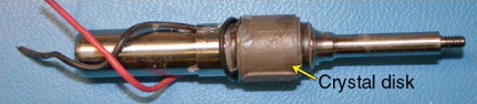
Figure 3.9 Photo of a quartz disk contained within a piezoelectric dental handpiece
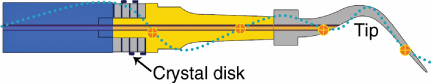
Figure 3.10 Diagram of a piezoelectric ultrasonic handpiece. Application of an alternating electrical current to the crystalline disk causes it to expand then contract, producing longitudinal vibrations that travel to the attached tip. Crosshairs denote nodal points (antinodes), or points of no movement or vibration
The components characteristic of a piezoelectric scaling unit are listed in Table 3.2 and illustrated by Figures 3.11–3.15.
Table 3.2 Components of piezoelectric ultrasonic units
| Component | Description | |
Tip
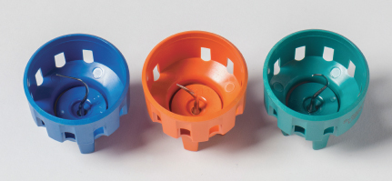 Figure 3.11 Piezoelectric tips and tip wrenches/carriers |
Screws onto handpiece by a torque-controlled wrench | |
Handpiece
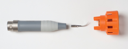 Figure 3.12 Handpiece of a piezoelectric unit to which the tip is attached using the torque wrench |
Embeds ceramic or crystal disks which encircle a metal bar. The terminal end of the bar is screw threaded to allow attachment of the tip | |
| Base unit | ||
| Houses controls which regulate power level and water flow; provides connection between foot switch and handpiece | ||
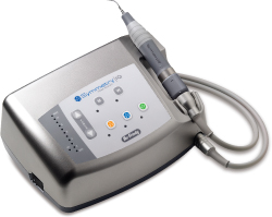 Figure 3.13 Symmetry IQ® piezoelectric scaler (Image courtesy of Hu-Friedy Mfg Co., LLC, Chicago IL, USA)
|
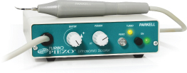 Figure 3.14 TurboPIEZO™ piezoelectric scaler (Image courtesy of Parkell, Inc.)
|
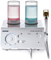 Figure 3.15 Piezon® Master 700 piezoelectric scaler (Image courtesy of Electro Medical Systems Corporation, Dallas, TX)
|
| Foot switch | When engaged, sends electrical current through base unit to the handpiece, activating movement of the tip | |
Oscillation of tip: Stroke pattern
The direction of movement (pattern of oscillation) produced by the tip of an ultrasonic scaling instrument influences instrumentation technique, specifically how the tip of the ultrasonic instrument is adapted to the tooth.
At the time of this writing, it is generally accepted that the pattern of oscillation, commonly referred to as the stroke pattern, is determined by the type of transducer, with piezoelectric scaling units producing a linear stroke pattern and magnetostrictive scaling units producing an elliptical stroke pattern.
A linear stroke pattern is one in which the tip of the instrument moves longitudinally forward and backward in one plane. With this linear pattern, the kinetic energy produced by the movement is distributed between only two surfaces of the tip – the back and the face (Figure 3.16b).
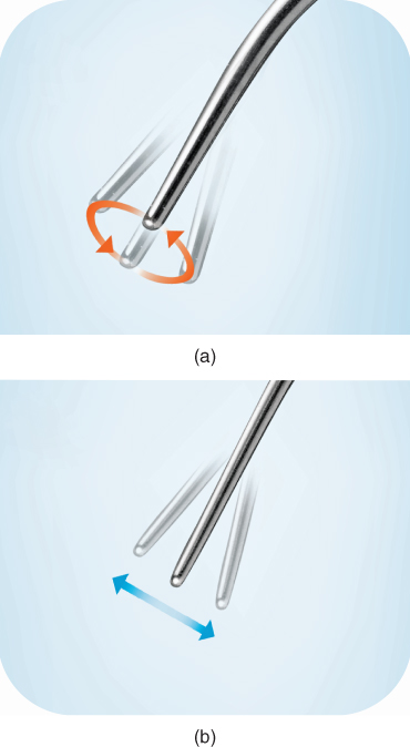
Figure 3.16 Tip oscillation in (a) an elliptical stroke pattern compared to (b) a linear stroke pattern
Therefore, adapting either the back or face of the tip against the tooth inherently delivers a high and potentially damaging degree of force perpendicular to the tooth surface. To avoid such undue force, it has been recommended that the lateral surfaces of a linear-movement tip be adapted to stroke parallel to the tooth surface in a sweeping-like motion.
An elliptical stroke pattern involves movement in multiple planes as the tip of the instrument moves longitudinally and transversely (laterally) in the shape of an oval or “ellipse” (Figure 3.16a). With this elliptical pattern, the kinetic energy produced by the movement is distributed among all surfaces – the back, face, and two lateral surfaces – of the tip.
This wide (among all surfaces) distribution of energy lessens the amount of energy directed to any one surface; therefore, any surface of an elliptical-movement tip can be adapted to the tooth without inherently exerting an overt amount of force to the tooth surface. The capacity to utilize any surface of the tip is advantageous to efficient debridement and will be addressed in greater detail in Chapter 6, Ultrasonic Instrumentation Technique.
The belief that piezoelectric scaling units produce linear stroke patterns and magnetostrictive scaling units produce elliptical stroke patterns resulted from the findings of several studies (Walmsley et al., 1986; Gankerseer and Walmsley, 1987), which utilized light microscopy (measurement of reflected light) to demonstrate the pattern of tip oscillation (Lea et al., 2002, 2009a). Since the time when these studies were conducted, newer technology has become available which utilizes scanning laser vibrometry to measure the oscillations of ultrasonic scaler tips three-dimensionally.
Using 3D laser vibrometry, Lea et al. (2009a) evaluated the oscillation patterns of piezoelectric and magnetostrictive ultrasonic instruments in loaded (adapted to a tooth) and unloaded (oscillating freely in air) conditions at low- and high-power settings. In contrast to the findings of the light microscopy studies, this study demonstrated that both piezoelectric and magnetostrictive scaling instruments oscillate in an elliptical pattern, with the magnitude of the lateral movement varying according to tip shape and power setting. These findings were further substantiated in a root surface defect study conducted by Lea et al. (2009b).
Box 3.1 Key point
Both piezoelectric and magnetostrictive tips oscillate in an elliptical pattern, with the broadness of the elliptical movement varying with power setting and tip shape.
In other words, the type of transducer, piezoelectric or magnetostrictive, does not determine the stroke pattern produced by the tip, as previously believed; both produce elliptical stroke patterns. The elliptical pattern will vary transversely from near-linear to broad depending on the power setting and tip shape. Slimmer tip shapes are more likely to produce broad elliptical movement, especially at higher power settings; low power and wider tip shapes are more likely to produce narrow (near-linear) elliptical movement (Lea et al., 2009a, 2009b). See Figures 3.17a,b and 3.18.
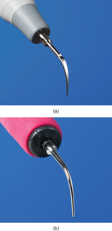
Figure 3.17 Tips designs evaluated by Lea et al., 2009a. (a) piezoelectric tip design; (b) magnetostrictive tip design. Note the broader/flatter design of the piezoelectric tip compared to the slimmer/cylindrical design of the magnetostrictive tip
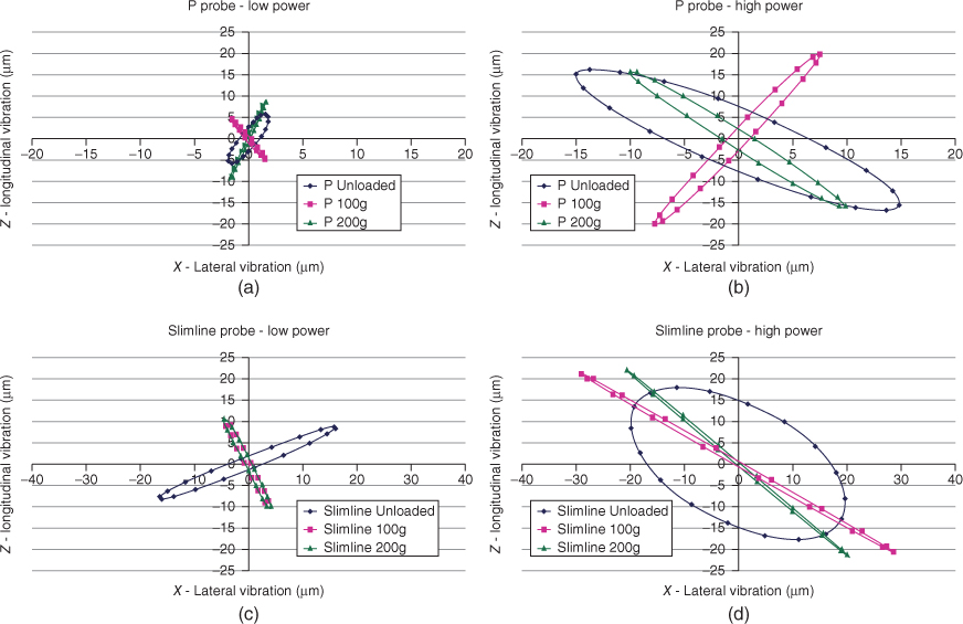
Figure 3.18 Oscillation patterns of loaded and unloaded P (broad/flat) and Slimline (slim/cylindrical) tips at high- and low-generator powers. Both tip designs demonstrate elliptical motion under load. Plots show P tip at (a) low power and (b) high power, and Slimline tip at (c) low power and (d) high power. Axes show probe displacement amplitudes measured in micrometer
As stated at the beginning of this discussion on oscillation, the stroke pattern of the tip influences instrumentation technique, specifically adaptation of the ultrasonic instrument. Based on this most recent evidence (Lea et al., 2009a, b), this textbook approaches ultrasonic instrumentation technique and tip selection from the perspective that both piezoelectric and magnetostrictive instruments produce an elliptical stroke pattern.
ULTRASONIC INSTRUMENTATION MECHANISMS OF ACTION
The high-frequency vibrations induced by both magnetostrictive and piezoelectric transducers are ultimately directed to the tip of the ultrasonic instrument. High-frequency oscillation of the tip produces mechanical and biophysical forces that disrupt and remove deposits on the surface of the tooth (Walmsley et al., 2008). These forces are considered the mechanisms of action by which ultrasonic instruments achieve debridement and are summarized in Table 3.3.
Table 3.3 Ultrasonic debridement mechanisms of action
| Mechanical | Vibratory action of the oscillating metal tip against the deposit ablates/breaks the deposit from the tooth surface |
| Irrigation | Lavage action of water flowing over tip flushes biofilm from the tooth surface and debris from the treatment site |
| Cavitation | Removal/disruption of biofilm by shock waves resulting from the implosion of bubbles |
| Acoustic microstreaming | Removal/disruption of biofilm by turbulent currents of water surrounding the tip |
Mechanical
The primary mechanism of ultrasonic debridement is mechanical (Walmsley et al., 1984, 1988; Lea et al., 2009b). The vibratory action of the oscillating metal tip against the deposit mechanically fractures or breaks the deposit from the tooth surface. Calculus removal with ultrasonic instruments generally occurs by ablation (or attrition) of the calcified deposit from the outer surface of the deposit down to the tooth surface (Figure 3.19a), but may also occur by breaking the calculus from the tooth at the tooth–deposit interface.
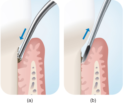
Figure 3.19 Calculus removal by (a) ablation or attrition of the calcified deposit from the outer surface of the calculus down to the tooth surface versus (b) breaking of the calculus from the tooth at the tooth–deposit interface
In contrast, manual scaling instruments and manual scaling technique are designed to break the bond between the tooth and deposit at the tooth–deposit interface (Figure 3.19b), although ablation of the deposit can also occur depending on a number of working parameters, including sharpness of the cutting edge and lateral force (Lea and Walmsley, 2009). Incomplete ablation of the calculus, whether by manual or ultrasonic instrumentation, is termed burnished calculus.
Irrigation
A flow of irrigant (typically water) cools the tip and creates a continuous lavage during instrumentation, which assists flushing of the debris from the treatment site and improving operator visibility. As the lavage extends to the full extent of the tip’s penetration into the periodontal pocket (Nosal et al., 1991), the removal of loosely attached biofilm and endotoxin from the root surface by the lavage likely occurs as well. Moore et al. (1986) demonstrated that 39% of endotoxin on periodontally involved roots could be removed by a gentle, one-minute washing of the root surface, and the removal of biofilm by low-velocity fluid streams with entrapped air bubbles has been demonstrated in vitro (Parini et al., 2005).
Cavitation and acoustic microstreaming
As the cooling water flows over the oscillating tip, ultrasonic energy is imparted into the water, generating two biophysical forces which likely contribute to the removal of biofilm – cavitation and acoustic microstreaming (Walmsley et al., 1992).
Cavitation is a hydrodynamic occurrence that can be defined as the formation and subsequent implosion of pulsating cavities, or “bubbles” in a flowing liquid that is the consequence of forces acting on the liquid (Laird and Walmsley, 1991). The bubbles are filled with water vapor/gas, so the implosion of the bubbles radiates shock waves or high-velocit/>
Stay updated, free dental videos. Join our Telegram channel
VIDEdental - Online dental courses


