Chapter 4
Ultrasonic tip design and selection
CHAPTER OBJECTIVES
On completion of this chapter, the student will be able to:
- Identify and define key elements of design common to all ultrasonic tips.
- Explain the influence of each element of design on the clinical performance of the ultrasonic tip.
- Recognize variables which influence tip selection.
- Select a tip design appropriate for the treatment objective and anatomy of the treatment site.
It was explained in Chapter 3 that ultrasonic instruments ablate and disrupt deposits by vibratory and biophysical mechanisms produced by a blunt metal tip oscillating at an ultrasonic frequency (Walmsley et al., 1984; Khambay and Walmsley, 1999), and that these mechanisms of action are influenced by several operational variables, including design of the blunt tip. The design of the tip is also one of several instrumentation technique variables presented in Chapter 6, which influence both deposit removal and root substance loss. Consequently, proper tip selection is a critical step in the implementation of successful debridement instrumentation.
Anatomy of An Ultrasonic Tip
All ultrasonic tips oscillate in an elliptical pattern, which disperses kinetic energy to each surface of the tip, rendering each surface of the active area of the tip clinically useful (Chapter 3). The active area of the tip is the free, unconstrained end of the tip at which displacement amplitude is maximized (see Figure 4.24). It extends approximately 4 mm in length from the last antinode to the terminal end of the tip. During ultrasonic instrumentation, the surfaces within the active area of the tip are adapted to the tooth surface. Figure 4.1 illustrates each surface and the active area of the ultrasonic tip.
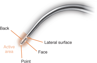
Figure 4.1 The various surfaces of an ultrasonic tip
The point of the tip, because of its small surface area, exerts a very concentrated output of energy that can easily and significantly damage the root surface. Consequently, the oscillating tip should never be adapted in a manner that places the point of the tip in contact with the root surface. Proper adaptation of the tip is presented in Chapters 6 and 7.
Delivery of cooling water to the tip is either internal (magnetostrictive only) or external (piezoelectric or magnetostrictive) to the tip (Figure 4.2). External delivery may allow the diameter of the tip to be slightly narrower than a comparable tip with internal water delivery. An advantage of internal tubing is that the water is delivered closer in proximity to the active area of the tip. While this more focused delivery probably allows the clinician to better manage the spray of water emitted, it does not reduce the amount of aerosol contamination produced during ultrasonic scaling (Rivera-Hidalgo et al., 1999).
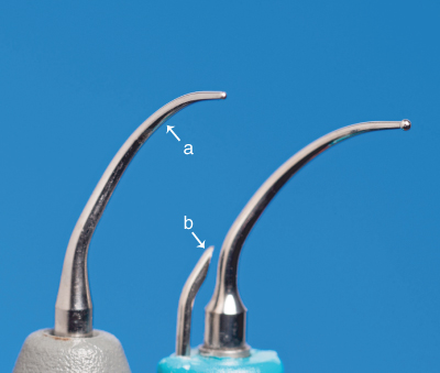
Figure 4.2 Comparison of tips with (a) internal and (b) external water portals
Key Elements of Tip Design
In order to utilize ultrasonic instrumentation as the primary means of periodontal debridement therapy, an adequate variety of tip designs are needed to effectively implement the staged approach to debridement proposed in Chapter 1 and presented in Chapter 6. Accordingly, manufacturers of ultrasonic instruments offer an assortment of tip configurations. Unlike the classification of hand instruments, which is fairly standardized among manufacturers, the systems used by manufacturers to identify and classify ultrasonic tip styles vary greatly, making tip selection and/or comparison by name or color-code complicated. Tip selection is simplified and made more precise by assessing key elements of design that are common to all ultrasonic tips (Table 4.1).
Table 4.1 Key elements of ultrasonic tip design
| Element | Impact |
| Dimension | |
| Diameter (width) of the active area of the tip |
|
| Shape | |
| Shape of the active area in cross section | |
| Geometry | |
| Number of planes crossed by the shank |
|
| Profile | |
| Number of bends in tip |
Tip dimension
The dimension, or diameter, of the tip is the width or thickness of the tip in the active area. Currently, tips fall into three categories by diameter: standard diameter, slim diameter, and ultraslim diameter (Figure 4.3).
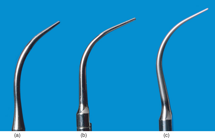
Figure 4.3 Comparison of the various ultrasonic tip diameters. (a) standard diameter; (b) slim diameter; (c) ultraslim diameter
The designation of standard, slim, or ultraslim diameter is an approximation, as standardization of widths (as measured in millimeters) for each category does not exist. Although the specific diameter of the tips in each category may vary slightly among manufacturers, there is within each category some consistency in the physical structure of the tips (Table 4.2).
Table 4.2 Classification of ultrasonic tips by diameter
| Diameter | Traits |
| Standard |
|
| Slim |
|
| Ultraslim |
|
The diameter of the tip primarily influences both the degree of force exerted and the amount of cavitational and streaming forces produced by the oscillating tip.
Influence of tip diameter on degree of force exerted
As previously explained, the net force exerted by an object (i.e., the oscillating ultrasonic tip) is a product of the object’s mass (m) multiplied by its acceleration (Hewitt, 1997) (Figure 4.4).

Figure 4.4 Newton’s Second Law of Motion. Net force equals mass multiplied by acceleration
The mass of an object is a measure in kilograms (kg) of the amount of matter in the object. Mass and force are directly proportional; therefore more mass equals greater force (Hewitt, 1997).
Given the influence of object mass on force, the mass (indicated by diameter) of the oscillating tip affects the degree of root surface damage and the efficiency of calculus removal, as the two are directly related.
At a given power setting or lateral force, significant increases in root substance loss occur with wide diameter compared with narrow or probe-shaped tips across all parameters of the root surface defect—width, depth, and volume (Jepsen et al., 2004) (Figure 4.5).
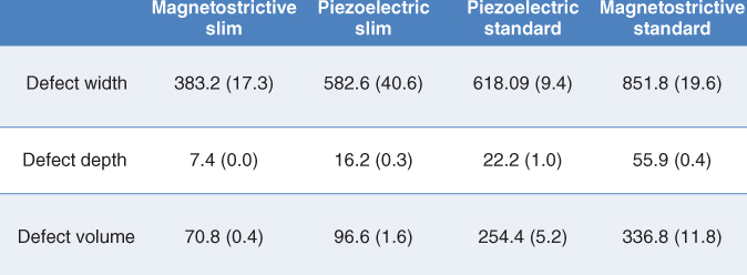
Figure 4.5 Defect values following three reciprocal (forward and backward) strokes at medium power setting, 0.7 N lateral pressure, and 0° angulation demonstrate an increase in root substance loss occurring with wide diameter compared with slim diameter tips. Data compiled from information found in Jepsen et al., 2004
The distinction between the depth and volume of the root surface defect is important. Defect depth appears to be a measure of the instrument’s capacity for root damage, whereas defect volume may be a gauge for the instrument’s efficacy of calculus removal (Flemmig et al., 1998a,b). This means that if the tips are oscillating against calculus, instead of root surface, the wider diameter tips are more efficacious at calculus removal compared to narrow diameter tips.
Influence of tip diameter on cavitation and microstreaming
The dimensions of the tip may be more influential than the displacement amplitude in the generation of cavitation (Walmsley et al., 2013). At any given displacement amplitude, unloaded wide diameter tips typically produce greater cavitational and streaming forces at the antinodes than unloaded slim diameter tips. This is attributed to the wider dimensions being more capable of displacing larger volumes of water (so producing greater cavitational and microstreaming forces) than narrower dimensions (Khambay and Walmsley, 1999; Felver et al., 2009; Walmsley et al., 2013).
However, the application of load (lateral pressure) increases the amount of cavitational activity occurring at the clinically pertinent active area of slim diameter tips more so than with wide diameter tips (Walmsley et al., 2013).
Influence of tip diameter on access to the treatment site
Slim diameter tips were designed with the intent of improving penetration to the base of the pocket because of their thinner, probe-like diameter. Depth of penetration into the periodontal pocket has been assessed in studies by evidence of instrumentation to the connective tissue attachment (Kawanami et al., 1988; Dragoo et al., 1992) or to the apical plaque border (APB) (Clifford et al., 1999). It can be argued that assessing the APB is a more useful measurement of instrument penetration (Chan et al., 2000), and that penetration past the APB, to the connective tissue attachment, may not be necessary or desirable (Claffey et al., 1988; Clifford et al., 1999).
Using disruption of the APB as the benchmark, standard and slim diameter tips are comparable (i.e., not statistically different) in their ability to adequately penetrate deep pockets (Kawanami et al., 1988; Dragoo et al., 1992; Clifford et al., 1999). This is noteworthy, as pocket depth is often (but mistakenly) cited by manufacturers and authors as an indication for use of a tip.
However, slim diameter tips do improve access to furcation anatomy and facilitate the effective use of ultrasonic instrumentation for prophylaxis procedures. Ultrasonic debridement with a narrow diameter tip has been demonstrated to be more effective than a standard Gracey curette in decreasing inflammation and motile forms of bacteria in Class II and Class III furcations, most likely due to better access resulting from the narrower diameter of the ultrasonic tip (Leon and Vogel, 1987). In patients with healthier periodontal tissues, the thin diameter of a slim or ultraslim tip facilitates access into the sulcus, expanding the utilization of ultrasonic instruments to prophylaxis procedures (Novaes Junior et al., 2004).
Tip shape
The shape of the tip denotes the shape of the active area in cross section, typically designed as either rectangular or circular (Figure 4.6). Tips with a rectangular cross section may be also be described as being “flat and broad” or “curette-like,” while tips with a circular cross section are more commonly referred to as being “cylindrical” or “probe-like.” Keep in mind that the shape of the tip is independent of the diameter of the tip: there are tips in the slim diameter category with a rectangular cross section, just as there are tips in the standard diameter category with a cylindrical cross section.
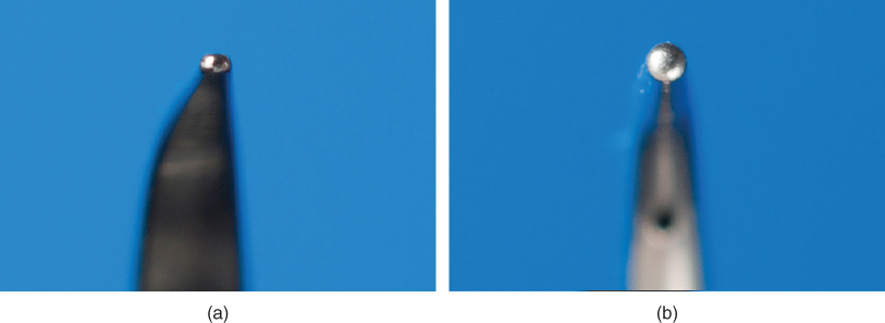
Figure 4.6 The shape of an ultrasonic tip in cross-section may be (a) rectangular or (b) circular
Similar to the impact of diameter, tip shape contributes to the degree of force exerted and the amount of cavitation produced by the oscillating tip. The surfaces of a rectangular shaped tip meet to form an edge. This edge, like the point of the tip, exerts a concentrated output of energy because of its reduced surface area, which may be beneficial for the scaling of heavy and/or tenacious calculus, but is detrimental for debridement of the root surface (Jepsen et al., 2004; Lea et al., 2009). Lea et al. found almost no difference in the depth and volume of root surface defects produced by slim diameter rectangular and cylindrical tips even though the cylindrical tip was oscillating at a higher displacement amplitude, demonstrating the greater force exerted by the rectangular tip. A rectangular shaped tip also produces more cavitation than a cylindrical tip of equal diameter, as its paddle-like shape is more conducive to the displacement of water (Khambay and Walmsley, 1999; Felver et al., 2009).
The shape of the tip additionally and notably influences the degree of contact achieved between the tip and the surface to be treated. As the primary mechanism of debridement is mechanical (Chapter 3), success is contingent on contact of the active area of the tip to the treatment surface; the greater the degree of contact between the active tip and the treatment surface, the greater the likelihood for thorough disruption and removal of the deposits.
A greater degree of contact results when the shape of the active portion of the tip conforms to the anatomy of the treatment site. For example, consider how the convex back surface of the cylindrical tip in Figure 4.6 better conforms to a root surface concavity than the relatively straight back surface of the rectangular tip.
Tip geometry
The geometry of the tip is defined by the number of planes that the shank of the tip crosses. The majority of tip designs extend in only one plane and so are geometrically straight. Tips which are curved in geometry are semi-spiral in design with a curvature to the side that extends the tip into a second plane (Figure 4.7).
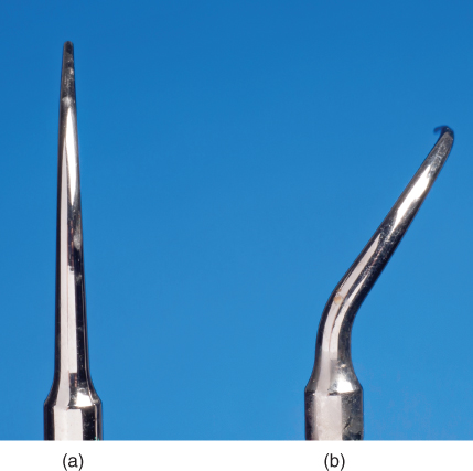
Figure 4.7 The geometry of an ultrasonic tip may be (a) straight or (b) curved
The geometry of the tip affects the clinician’s ability to access the treatment site and make adequate contact with the surface to be treated.
Influence of tip geometry on access to the treatment site
A straight shank is appropriate when access to the treatment site is uncomplicated, such as with the coronal surfaces of all teeth and the typically flat root surfaces of anterior teeth (Figure 4.8). The straight alignment also allows the clinician to easily estimate the position of the tip within the periodontal pocket (Clifford et al., 1999).
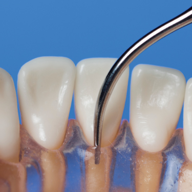
Figure 4.8 A straight ultrasonic tip readily adapts to the characteristically flat root surfaces of anterior teeth
When access to the treatment site is complex, as generally occurs when instrumenting the root surfaces of posterior teeth, a curved shank is indicated. The contra-angle of the shank is required to adapt the tip around the maximal contour of the tooth surface so that the tip reaches the site and is in a position that facilitates proper ultrasonic instrumentation technique (Chapter 6) (Figure 4.9).
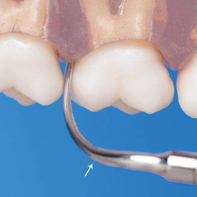
Figure 4.9 The contra-angle (indicated by arrow) of a curved tip facilitates access and adaptation of the active tip area to posterior root surfaces
Influence of tip geometry on degree of contact
Subsequent to accessing the treatment site, the tip then needs to make adequate contact with deposits in order for disruption and removal to occur. The geometry of the tip influences the degree of contact achieved in that a tip with a straight shank typically is straight in the active area as well, whereas a tip with a curved shank may arc in the active area (Figure 4.10).
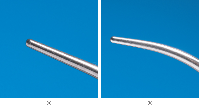
Figure 4.10 Comparison of the active areas of a (a) straight and (b) curved ultrasonic tip
A straight active tip area conforms to the curvatures of the tooth to a lesser degree than does a curv/>
Stay updated, free dental videos. Join our Telegram channel
VIDEdental - Online dental courses


