This article on x-ray cone-beam CT (CBCT) acquisition provides an overview of the fundamental principles of operation of this technology and the influence of geometric and software parameters on image quality and patient radiation dose. Advantages of the CBCT system and a summary of the uses and limitations of the images produced are discussed. All current generations of CBCT systems provide useful diagnostic images. Future enhancements most likely will be directed toward reducing scan time; providing multimodal imaging; improving image fidelity, including soft tissue contrast; and incorporating task-specific protocols to minimize patient dose.
Imaging is an important diagnostic adjunct to the clinical assessment of the dental patient. The introduction of panoramic radiography in the 1960s and its widespread adoption throughout the 1970s and 1980s heralded major progress in dental radiology, providing clinicians with a single comprehensive image of jaws and maxillofacial structures. However, intraoral and extraoral procedures, used individually or in combination, suffer from the same inherent limitations of all planar two-dimensional (2D) projections: magnification, distortion, superimposition, and misrepresentation of structures. Numerous efforts have been made toward three-dimensional (3D) radiographic imaging (eg, stereoscopy, tuned aperture CT) and although CT has been available, its application in dentistry has been limited because of cost, access, and dose considerations. The introduction of cone-beam computed tomography (CBCT) specifically dedicated to imaging the maxillofacial region heralds a true paradigm shift from a 2D to a 3D approach to data acquisition and image reconstruction. Interest in CBCT from all fields of dentistry is unprecedented because it has created a revolution in maxillofacial imaging, facilitating the transition of dental diagnosis from 2D to 3D images and expanding the role of imaging from diagnosis to image guidance of operative and surgical procedures by way of third-party applications software.
The purpose of this article is to provide an overview of this CBCT technology and an understanding of the influence of technical parameters on image quality and resultant patient radiation exposure.
Background
CBCT is a recent technology. Imaging is accomplished by using a rotating gantry to which an x-ray source and detector are fixed. A divergent pyramidal- or cone-shaped source of ionizing radiation is directed through the middle of the area of interest onto an area x-ray detector on the opposite side. The x-ray source and detector rotate around a rotation fulcrum fixed within the center of the region of interest. During the rotation, multiple (from 150 to more than 600) sequential planar projection images of the field of view (FOV) are acquired in a complete, or sometimes partial, arc. This procedure varies from a traditional medical CT, which uses a fan-shaped x-ray beam in a helical progression to acquire individual image slices of the FOV and then stacks the slices to obtain a 3D representation. Each slice requires a separate scan and separate 2D reconstruction. Because CBCT exposure incorporates the entire FOV, only one rotational sequence of the gantry is necessary to acquire enough data for image reconstruction ( Fig. 1 ).
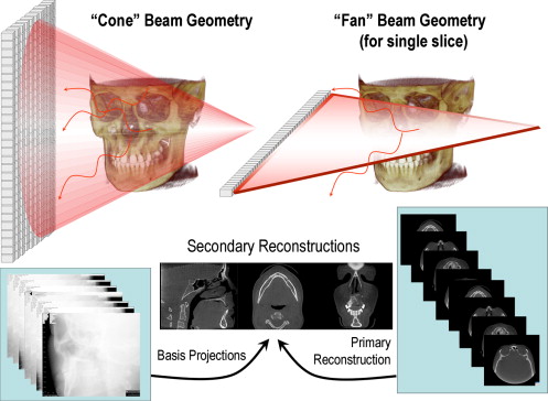
CBCT was initially developed for angiography , but more recent medical applications have included radiotherapy guidance and mammography . The cone-beam geometry was developed as an alternative to conventional CT using either fan-beam or spiral-scan geometries, to provide more rapid acquisition of a data set of the entire FOV and it uses a comparatively less expensive radiation detector. Obvious advantages of such a system, which provides a shorter examination time, include the reduction of image unsharpness caused by the translation of the patient, reduced image distortion due to internal patient movements, and increased x-ray tube efficiency. However, its main disadvantage, especially with larger FOVs, is a limitation in image quality related to noise and contrast resolution because of the detection of large amounts of scattered radiation.
It has only been since the late 1990s that computers capable of computational complexity and x-ray tubes capable of continuous exposure have enabled clinical systems to be manufactured that are inexpensive and small enough to be used in the dental office. Two additional factors have converged to make CBCT possible.
Development of compact high-quality two-dimensional detector arrays
The demands on any x-ray detector in clinical CBCT are hard to fulfill. The detector must be able to record x-ray photons, read off and send the signal to the computer, and be ready for the next acquisition many hundreds of times within a single rotation. Rotation is usually performed within times equivalent to, or less than, panoramic radiography (10–30 seconds), which necessitates frame rate image acquisition times of milliseconds. Detectors were initially produced using a configuration of scintillation screens, image intensifiers, and charge-coupled device (CCD) detectors. However, image intensifier systems are large and bulky and FOVs may suffer from peripheral truncation effects (volumetric “cone cuts”), having circular entrance areas rather than more appropriate rectangular ones. Furthermore, rotation of the source-to-detector arrangement may influence sensitivity because of the interference between the magnetic field of the earth and those in the image intensifiers. More recently, high-resolution, inexpensive flat-panel detectors have become available. Such flat detectors are composed of a large-area pixel array of hydrogenated amorphous silicon thin-film transistors. X rays are detected indirectly by means of a scintillator, such as terbium-activated gadolinium oxysulphide or thallium-doped cesium iodide, which converts X rays into visible light that is subsequently registered in the photo diode array. The configuration of such detectors is less complicated and offers greater dynamic range and reduced peripheral distortion; however, these detectors require a slightly greater radiation exposure.
Refinement of approximate cone-beam algorithms
Reconstructing 3D objects from cone-beam projections is a fairly recent accomplishment. In conventional fan-beam CT, individual axial slices of the object are sequentially reconstructed using a well-known mathematic technique (filtered back projection) and subsequently assembled to construct the volume. However, with 2D x-ray area detectors and cone-beam geometry, a 3D volume must be reconstructed from 2D projection data, which is referred to as “cone-beam reconstruction.” The first and most popular approximate reconstruction scheme for cone-beam projections acquired along a circular trajectory is the algorithm according to Feldkamp and colleagues , referred to as the Feldkamp, Davis, and Kress (FDK) method. This algorithm, used by most research groups and commercial vendors for CBCT with 2D detectors, uses a convolution-back projection method. Although it can be implemented easily with currently available hardware and is a good reconstruction for images at the center or “midplane” of the cone beam, it provides an approximation that causes some unavoidable distortion in the noncentral transverse planes, and resolution degradation in the longitudinal direction. To address this deficiency, several other approaches have been proposed using different algorithms and cone-beam geometries (eg, dual orthogonal circles, helical orbit, orthogonal circle-and-line), and these will no doubt be incorporated into future CBCT designs.
Cone-beam CT image production
Current cone-beam machines scan patients in three possible positions: (1) sitting, (2) standing, and (3) supine. Equipment that requires the patient to lie supine physically occupies a larger surface area or physical footprint and may not be accessible for patients with physical disabilities. Standing units may not be able to be adjusted to a height to accommodate wheelchair-bound patients. Seated units are the most comfortable; however, fixed seats may not allow scanning of physically disabled or wheelchair-bound patients. Because scan times are often greater than those required for panoramic imaging, perhaps more important than patient orientation is the head restraint mechanism used. Despite patient orientation within the equipment, the principles of image production remain the same.
The four components of CBCT image production are (1) acquisition configuration, (2) image detection, (3) image reconstruction, and (4) image display. The image generation and detection specifications of currently available systems ( Table 1 ) reflect proprietary variations in these parameters.
| Unit | Model(s) | Manufacture/distributor |
|---|---|---|
| Accuitomo | 3D Accuitomo – XYZ Slice View Tomograph/Veraviewpacs 3D | J. Morita Mfg. Corp., Kyoto, Japan |
| Galileos | — | Sirona Dental Systems, Charlotte, North Carolina |
| Hitachi | CB MercuRay/CB Throne | Hitachi Medical Systems, Tokyo, Japan |
| i-CAT | Classic/Next Generation | Imaging Sciences International, Hatfield, Pennsylvania |
| ILUMA | Ultra Cone Beam CT Scanner | IMTEC Imaging, Ardmore, Oklahoma; distributed by KODAK Dental Systems, Carestream Health, Rochester, New York |
| KaVo | 3D eXam | KaVo Dental Corp., Biberach, Germany |
| KODAK | 9000 3D | KODAK Dental Systems, Carestream Health, Rochester, New York |
| NewTom | 3G/NewTom VG | QR, Inc., Verona, Italy/Dent-X Visionary Imaging, Elmsford, New York |
| Picasso Series | Trio/Pro/Master | E-Woo Technology Co., Ltd./Vatech, Giheung-gu, Korea |
| PreXion 3D | TeraRecon Inc., San Mateo, California | |
| Promax | 3D | Planmeca OY, Helsinki, FInland |
| Scanora | 3D Dental conebeam | SOREDEX, Helsinki, Finland |
| SkyView | 3D Panoramic imager | My-Ray Dental Imaging, Imola, Italy |
Acquisition configuration
The geometric configuration and acquisition mechanics for the cone-beam technique are theoretically simple. A single partial or full rotational scan from an x-ray source takes place while a reciprocating area detector moves synchronously with the scan around a fixed fulcrum within the patient’s head.
X ray generation
During the scan rotation, each projection image is made by sequential, single-image capture of attenuated x-ray beams by the detector. Technically, the easiest method of exposing the patient is to use a constant beam of radiation during the rotation and allow the x-ray detector to sample the attenuated beam in its trajectory. However, continuous radiation emission does not contribute to the formation of the image and results in greater radiation exposure to the patient. Alternately, the x-ray beam may be pulsed to coincide with the detector sampling, which means that actual exposure time is markedly less than scanning time. This technique reduces patient radiation dose considerably. Currently, four units (Accuitomo, CB MercuRay, Iluma Ultra Cone, and PreXion 3D) provide continuous radiation exposure. Pulsed x-ray beam exposure is a major reason for considerable variation in reported cone-beam unit dosimetry.
Field of view
The dimensions of the FOV or scan volume able to be covered depend primarily on the detector size and shape, the beam projection geometry, and the ability to collimate the beam. The shape of the scan volume can be either cylindric or spherical (eg, NewTom 3G). Collimation of the primary x-ray beam limits x-radiation exposure to the region of interest. Field size limitation therefore ensures that an optimal FOV can be selected for each patient, based on disease presentation and the region designated to be imaged. CBCT systems can be categorized according to the available FOV or selected scan volume height as follows:
-
Localized region: approximately 5 cm or less (eg, dentoalveolar, temporomandibular joint)
-
Single arch: 5 cm to 7 cm (eg, maxilla or mandible)
-
Interarch: 7 cm to 10 cm (eg, mandible and superiorly to include the inferior concha)
-
Maxillofacial: 10 cm to 15 cm (eg, mandible and extending to Nasion)
-
Craniofacial: greater than 15 cm (eg, from the lower border of the mandible to the vertex of the head)
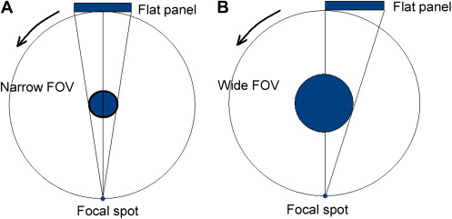
Extended FOV scanning incorporating the craniofacial region is difficult to incorporate into cone-beam design because of the high cost of large-area detectors. The expansion of scan volume height has been accomplished by one unit (iCAT Extended Field of View model) by the software addition of two rotational scans to produce a single volume with a 22-cm height. Another novel method for increasing the width of the FOV while using a smaller area detector, thereby reducing manufacturing costs, is to offset the position of the detector, collimate the beam asymmetrically, and scan only half the patient (eg, Scanora 3D, SOREDEX, Helsinki, Finland) ( Fig. 2 ).
Scan factors
During the scan, single exposures are made at certain degree intervals, providing individual 2D projection images, known as “basis,” “frame,” or “raw” images. These images are similar to lateral and posterior-anterior “cephalometric” radiographic images, each slightly offset from one another. The complete series of images is referred to as the “projection data.” The number of images comprising the projection data throughout the scan is determined by the frame rate (number of images acquired per second), the completeness of the trajectory arc, and the speed of the rotation. The number of projection scans comprising a single scan may be fixed (eg, NewTom 3G, Iluma, Galileos, or Promax 3D) or variable (eg, i-CAT, PreXion 3D). More projection data provide more information to reconstruct the image; allow for greater spatial and contrast resolution; increase the signal-to-noise ratio, producing “smoother” images; and reduce metallic artifacts. However, more projection data usually necessitate a longer scan time, a higher patient dose, and longer primary reconstruction time. In accordance with the “as low as reasonably achievable” (ALARA) principle, the number of basis images should be minimized to produce an image of diagnostic quality.
Frame rate and speed of rotation
Higher frame rates provide images with fewer artifacts and better image quality . However, the greater number of projections proportionately increases the amount of radiation a patient receives. Detector pixels must be sensitive enough to capture radiation adequate to register a high signal-to-noise output and to transmit the voltage to the analog and the digital converter, all within a short arc of exposure. Within the limitations of solid-state detector readout speed and the need of short scanning time in a clinical setting, the total number of available view angles is normally limited to several hundred.
Completeness of the trajectory arc
Most CBCT imaging systems use a complete circular trajectory or a scan arc of 360° to acquire projection data. This physical requirement is usually necessary to produce projection data adequate for 3D reconstruction using the FDK algorithm (see section on reconstruction). However, it is theoretically possible to reduce the completeness of the scanning trajectory and still reconstruct a volumetric data set. This approach potentially reduces the scan time and is mechanically easier to perform. However, images produced by this method may have greater noise and suffer from reconstruction interpolation artifacts. Currently, this technique is used by at least two units (Galileos and Promax 3D).
Cone-beam CT image production
Current cone-beam machines scan patients in three possible positions: (1) sitting, (2) standing, and (3) supine. Equipment that requires the patient to lie supine physically occupies a larger surface area or physical footprint and may not be accessible for patients with physical disabilities. Standing units may not be able to be adjusted to a height to accommodate wheelchair-bound patients. Seated units are the most comfortable; however, fixed seats may not allow scanning of physically disabled or wheelchair-bound patients. Because scan times are often greater than those required for panoramic imaging, perhaps more important than patient orientation is the head restraint mechanism used. Despite patient orientation within the equipment, the principles of image production remain the same.
The four components of CBCT image production are (1) acquisition configuration, (2) image detection, (3) image reconstruction, and (4) image display. The image generation and detection specifications of currently available systems ( Table 1 ) reflect proprietary variations in these parameters.
| Unit | Model(s) | Manufacture/distributor |
|---|---|---|
| Accuitomo | 3D Accuitomo – XYZ Slice View Tomograph/Veraviewpacs 3D | J. Morita Mfg. Corp., Kyoto, Japan |
| Galileos | — | Sirona Dental Systems, Charlotte, North Carolina |
| Hitachi | CB MercuRay/CB Throne | Hitachi Medical Systems, Tokyo, Japan |
| i-CAT | Classic/Next Generation | Imaging Sciences International, Hatfield, Pennsylvania |
| ILUMA | Ultra Cone Beam CT Scanner | IMTEC Imaging, Ardmore, Oklahoma; distributed by KODAK Dental Systems, Carestream Health, Rochester, New York |
| KaVo | 3D eXam | KaVo Dental Corp., Biberach, Germany |
| KODAK | 9000 3D | KODAK Dental Systems, Carestream Health, Rochester, New York |
| NewTom | 3G/NewTom VG | QR, Inc., Verona, Italy/Dent-X Visionary Imaging, Elmsford, New York |
| Picasso Series | Trio/Pro/Master | E-Woo Technology Co., Ltd./Vatech, Giheung-gu, Korea |
| PreXion 3D | TeraRecon Inc., San Mateo, California | |
| Promax | 3D | Planmeca OY, Helsinki, FInland |
| Scanora | 3D Dental conebeam | SOREDEX, Helsinki, Finland |
| SkyView | 3D Panoramic imager | My-Ray Dental Imaging, Imola, Italy |
Acquisition configuration
The geometric configuration and acquisition mechanics for the cone-beam technique are theoretically simple. A single partial or full rotational scan from an x-ray source takes place while a reciprocating area detector moves synchronously with the scan around a fixed fulcrum within the patient’s head.
X ray generation
During the scan rotation, each projection image is made by sequential, single-image capture of attenuated x-ray beams by the detector. Technically, the easiest method of exposing the patient is to use a constant beam of radiation during the rotation and allow the x-ray detector to sample the attenuated beam in its trajectory. However, continuous radiation emission does not contribute to the formation of the image and results in greater radiation exposure to the patient. Alternately, the x-ray beam may be pulsed to coincide with the detector sampling, which means that actual exposure time is markedly less than scanning time. This technique reduces patient radiation dose considerably. Currently, four units (Accuitomo, CB MercuRay, Iluma Ultra Cone, and PreXion 3D) provide continuous radiation exposure. Pulsed x-ray beam exposure is a major reason for considerable variation in reported cone-beam unit dosimetry.
Field of view
The dimensions of the FOV or scan volume able to be covered depend primarily on the detector size and shape, the beam projection geometry, and the ability to collimate the beam. The shape of the scan volume can be either cylindric or spherical (eg, NewTom 3G). Collimation of the primary x-ray beam limits x-radiation exposure to the region of interest. Field size limitation therefore ensures that an optimal FOV can be selected for each patient, based on disease presentation and the region designated to be imaged. CBCT systems can be categorized according to the available FOV or selected scan volume height as follows:
-
Localized region: approximately 5 cm or less (eg, dentoalveolar, temporomandibular joint)
-
Single arch: 5 cm to 7 cm (eg, maxilla or mandible)
-
Interarch: 7 cm to 10 cm (eg, mandible and superiorly to include the inferior concha)
-
Maxillofacial: 10 cm to 15 cm (eg, mandible and extending to Nasion)
-
Craniofacial: greater than 15 cm (eg, from the lower border of the mandible to the vertex of the head)
Extended FOV scanning incorporating the craniofacial region is difficult to incorporate into cone-beam design because of the high cost of large-area detectors. The expansion of scan volume height has been accomplished by one unit (iCAT Extended Field of View model) by the software addition of two rotational scans to produce a single volume with a 22-cm height. Another novel method for increasing the width of the FOV while using a smaller area detector, thereby reducing manufacturing costs, is to offset the position of the detector, collimate the beam asymmetrically, and scan only half the patient (eg, Scanora 3D, SOREDEX, Helsinki, Finland) ( Fig. 2 ).


