Orthodontics and cone beam computed tomography technology have evolved tremendously in the last 10 years. The technology has evolved from a predominantly diagnostic entity to a true clinical and translational product. One can believe that this technology is here to stay and it has a real role to revolutionize the efficiency and effectiveness of orthodontic care. This article discusses the current advancements and use of cone beam computed tomography.
Key points
- •
For any orthodontic analysis to adequately diagnose the skeletal jaw relationship, the three-dimensional image needs to incorporate the skull base, the facial bones, and the dentition. This requires a field of view (FOV) larger than the one used in routine dental check-up.
- •
One of the major advantages of CBCT over conventional CT is the reduced radiation dose. However, compared with a conventional lateral cephalogram, a panoramic radiograph, and any supplemental films that are required, the radiation dose of CBCTs is still relatively higher.
- •
The analysis of soft tissues of the face is an important part of planning and evaluation of orthodontic treatment. Traditional methods of soft tissue analysis include measuring distances, angles, areas, and volumes based on the analysis of landmarks or points that have specific geometric locations.
- •
CBCT has become a vital tool in evaluating multidisciplinary orthodontic cases that require surgical planning. It has shown major advancements over the two-dimensional imaging modalities when it comes to surgery simulation, analysis of condylar resorption, and facial asymmetry evaluation.
Introduction
Some 10 years ago, when the first papers were published on cone beam computed tomography (CBCT) technology, many authors were highly enthusiastic and excited about the possibilities of this innovation, even to the point of making this a routine procedure in the everyday clinical practice. The premise of such excitement stemmed from the increased capacity to understand head and neck anatomy and to harness the information for clinical and practical usage.
CBCT technology has certainly come along way. In one of the earliest reviews of this technology, only four mainstream vendors had machines or devices available in the marketplace. Today, almost 30 to 40 variations of CBCT devices are available and these are manufactured by many commercial entities.
Indeed, the technology has improved over the last decade. This article discusses the current advancements and uses of CBCT. Many in the dental profession have touted that a specialist and an expert normally require 10 years of experience in a given technology and the past decade has certainly allowed us to reflect on the lessons learned on the job.
Hardware: field of view variation
The variations in volume capture, also known as field of view (FOV), for all cone beam devices range from 5 to 45.7 cm. Kau described the categorization of CBCT devices largely on the clinical indication and need. Small FOV devices (normally 5–10 cm) give the orthodontist a three-dimensional view of a single tooth unit and its surrounding anatomy. This specific FOV is used for assessing individual teeth, such as impacted teeth, root morphology, supernumeraries, sites for placement of dental implants, and temporary anchorage devices. Medium FOV units provide single jaw anatomy, whereas the maxillomandibular FOV gives the clinician an understanding of two-jaw anatomy, temporomandibular joint (TMJ), and occlusion. These FOVs are typically used when additional information on occlusal relationships, facial asymmetries, and bilateral TMJ evaluations are needed or when the conditions of interest, such as potential adverse boundary conditions, are present in both arches or jaws. Finally, craniofacial or large FOVs include the cranium, cranial base, and all associated structures. The large FOVs incorporate most of the whole head and help clinicians to visualize relationships between skeletal bases, between teeth and skeletal bases, and significant anomalies in patients requiring orthognathic surgery or those with craniofacial anomalies.
It is not uncommon for orthodontists to work in the FOV between 15 and 30 cm. The 15-cm FOV is used when the clinician wants images restricted to one jaw. Using the 22-cm FOV makes it possible to visualize both jaws, and depending on the size of the patient, all the craniofacial complex. In most circumstances, the orthodontist normally has to select a FOV of 30 cm or more to have a complete picture ( Fig. 1 ).
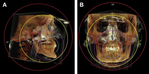
For any orthodontic analysis to adequately diagnose the skeletal jaw relationship, the three-dimensional image needs to incorporate the skull base, facial bones, and dentition. This requires a FOV size larger than the one used in routine dental check-up. In general, the orthodontist needs to visualize the anatomic structures that include nasion on the anterior-superior border of the image, and the mandibular points pogonion, gnathion, and menton on the anterior-inferior border. The posterior FOV must include the sella turcica, the TMJ (condylion), skull base (basion), and posterior contour of the mandible (gonion). In addition, all the cervical vertebrae to C4 need to be visible on the tomography, allowing analysis of skeletal maturation.
Image analysis
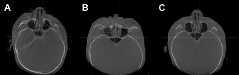
After obtaining the three-dimensional image of interest, each orthodontist should start by assessing the quality of the image. In all circumstances, a conscious decision should be made to accept the quality of the image (sometimes with some deficiencies) or to reacquire the image. This decision has to be made in conjunction with the patient’s parameters in mind: age of the patient, ability to cooperate, and number of exposures before this image acquisition ( Fig. 2 ).
Next, a systematic approach to evaluate important structures, such as the sinuses, TMJs, osseous structures, teeth, and soft tissues, should be done. Each region of interest needs to be evaluated from at least two planes at right angles to each other. This approach offers a multidimensional perspective. The clinician may also view the volumetric rendering in a three-dimensional format. Additionally, the clinician should scan through a consecutive series of two-dimensional views in any given plane over the entire region of interest.
Radiation dose
One of the major advantages of CBCT over conventional CT is the reduced radiation dose. However, compared with a conventional lateral cephalogram, a panoramic radiograph, and any supplemental films that are required, the radiation dose of CBCTs is still relatively higher. A recent report stated that CBCT imaging normally used for comprehensive orthodontic patients was about 65 mSv, compared with about 26 mSv for a lateral cephalogram and a panoramic image taken on their digital machine. However, rapid advances in CBCT technology have resulted in three-dimensional images that have about 2% or less of annual background radiation, which is only slightly more than conventional orthodontic imaging.
Recently, the recommendations of the International Commission on Radiological Protection regarding dose calculation were generally agreed to include the salivary glands and the oral mucosa as weighting factors in the calculations. As a result, the doses calculated using this method create higher doses than previous estimates. A summary of dose calculations may be found in the literature.
The dose can also range substantially depending on the equipment, the FOV, and specific technical factors (milliampere and kilovolt). It has been reported that the estimated effective dose from a wide range of CBCT scanners varies from 19 to 265 μSv. This report concluded that a single average effective dose is not a concept that can be used with CBCT because of multiple confounding factors. One such factor is unit variations at different time points. It has been reported that significant differences in dose exist for different CBCT machines, and also there are differences in dose for different examinations or techniques with the same unit.
Based on these findings, scans should have an exposure protocol that leads to an acceptable image for their specific indication. Justification and optimization are inextricably linked, because the dose is reduced by choosing a small FOV and a lower resolution; by reducing the dose, the net benefit to the patient increases. It has been shown that reducing the scan height or the FOV from the larger size to the next available smaller size results in a significant reduction, up to 50%, in the radiation dosage to the patient. However, in an orthodontic patient, the needs are slightly different because the skeletal relationship is paramount in the diagnosis. Hence, the anterior cranial base (which traditionally has been regarded as a stable structure for CBCT superimposition) is required. This is a serious dilemma for the orthodontist: dose versus clinical need.
To date, the relevant authorities in orthodontics have not imposed strict recommendations on the use of CBCT image acquisition. The American Association of Orthodontists made a recommendation in 2010, stating: “the AAO recognizes that while there may be clinical situations where a CBCT radiograph may be of value, the use of such technology is not routinely required for orthodontic radiography.” In addition, the British Orthodontic Society guidelines give a similar recommendation: “routine use of CBCT even for most cases of impaction of teeth … cannot yet be recommended.”
At present, image acquisition should follow the “need to basis” and where the image acquired is used for patient care and a clinical advantage.
Software improvements
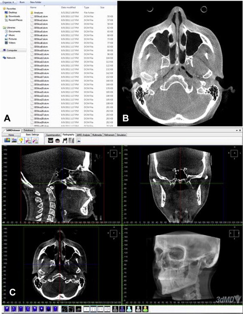
CBCTs are acquired and saved in a Digital Imaging and Communications in Medicine (DICOM) format. In general, a DICOM record consists of a DICOMDIR file, which includes patient information, specific information about image acquisition, and a list of images that correspond to axial slices forming the three-dimensional image; and several sequentially coded images that correspond to the axial slices ( Fig. 3 ).
Facial soft tissue analysis
The analysis of soft tissues of the face is an important part of planning and evaluation of orthodontic treatment. Traditional methods of soft tissue analysis include measuring distances, angles, areas, and volumes based on the analysis of landmarks or points that have specific geometric locations. Normally, 20 to 40 landmarks are used to describe a face and some landmarks may be difficult to identify. This problem affects the reproducibility and reliability of facial soft tissue landmarks. In addition, there are also individual dependent errors in placing landmarks. Poorer reproducibility was noticed more in the interexaminer assessment than intraexaminer assessment because of the visual acuity and discipline.
It has been shown that CBCT images using routine scanning protocols are reliable for measuring soft tissue thickness in the facial region. CBCTs can also be used in combination with three-dimensional images of the facial soft tissue obtained with stereophotogrammetry, structured light systems, and laser acquisition systems, which provide the same degree of information with a more accurate representation of facial morphologies, for diagnostic, treatment planning, and posttreatment evaluation purposes.
Landmark-based methods of geometric morphometrics alone are difficult to fulfill the task of soft tissue analysis. The most common techniques to analysis facial soft tissue are the constructing of average three-dimensional facial images and its superimposition. Based on the facial morphology of the studied populations, average faces were constructed by using previously validated software. These applications may include studying facial anomalies in comparison with normal facial morphology; evaluating average facial growth in a cohort of subjects; comparing facial morphologies for different ages, genders, and populations ; and diagnosing people with diseases that affect facial morphology, such as Binder syndrome and hip dysplasia.
Hard tissue analysis
With the help of different software systems, CBCTs can be used to generate volumetric three-dimensional skeletal views. These views allow surface observation of the osseous morphology of the skeleton and exploration of the internal root shape, alveolar nerve position, and airway information. By the means of registration, superimposition, and three-dimensional color-coded displacement maps, CBCTs can assess bone remodeling during growth and also help to visualize treatment effects and to accurately quantify these measurement.
The traditional cephalometric analysis in orthodontics is an essential tool to diagnose and evaluate the treatment outcomes by evaluation of craniofacial morphology. Conventional two-dimensional lateral cephalometric images may be derived from a perspective projection and the inherent magnification of the image depends on the distance from the structure to the film. This might cause double lower border of the mandible and hides the true skeletal asymmetry, and increases the identification errors. Three-dimensional cephalometric approaches can correct this error by reconstruction process and are very reliable and accurate for the detection of mandibular asymmetry. The three-dimensional cephalometric analysis gives more information, such as the possibility of comparing the right and left side of the skull and the possibility of generating independent analysis on both sides, and the nonsuperimposed bilateral anatomic structures can be identified more precisely than traditional cephalometric landmarks. Different studies also showed the accuracy of cephalometric measurements from three-dimensional reconstructed images, the measurements were valid, and they demonstrated a high degree of precision.
Several methods were used to synthesize the lateral cephalograms from the CBCT scans. The maximum intensity projection technique projects on the visualization plane the voxel with the highest intensity from the viewpoint to the plane of projection to generate the cephalograms. It displays three-dimensional structures in a solid-like way and could represent the overall morphology of tissues. However, it also might prejudice the recognition of specific anatomic landmarks and reduce the reproducibility. In the Ray Cast techniques, the three-dimensional data are visualized by summing all values of the voxels from the viewpoint to the plane of projection and dividing this number by the number of voxels. This means the measurements are not as spread out as with the maximum intensity projection technique. Landmarks used in cephalometry can be identified on CBCT-synthesized cephalograms and the accuracy of linear and angular measurements performed on CBCT-synthesized cephalograms are not different from conventional lateral cephalometric analyses. It is noteworthy that the orientation of the head in CBCT images may not only affect the reliability of the measurements in CBCT-generated cephalograms, but also the relative location of anatomy, and therefore diagnosis and treatment planning.
Stay updated, free dental videos. Join our Telegram channel
VIDEdental - Online dental courses


