Introduction
The purpose of this study was to compare the transverse, vertical, and anteroposterior skeletal and dental changes in adolescents receiving expansion treatment with tooth-borne and bone-anchored expanders. Immediate and long-term changes were measured on cone-beam computed tomography (CBCT) images.
Methods
Sixty-two patients needing maxillary expansion were randomly allocated to 1 of 3 groups: traditional hyrax tooth-borne expander, bone-anchored expander, and control. CBCT images were taken at baseline, immediately after expansion, after removal of the appliance (6 months), and just before fixed bonding (12 months). Repeated measures multivariate analysis of variance (MANOVA) was applied to the distances and angles measured to determine the statistical significance in the immediate and long time periods. Bonferroni post-hoc tests were used to identify significant differences between the treatment groups.
Results
Immediately after expansion, the subjects in the tooth-borne expander group had significantly more expansion at the crown level of the maxillary first premolars ( P = 0.003). Dental crown expansion was greater than apical expansion and skeletal expansion with both appliances. The control group showed little change (growth) over the 6-month interval. At 12 months, no group had a statistically significant difference in angle changes, suggesting symmetric expansion. Both treatment groups had significant long-term expansion at the level of the maxillary first molar crown and root apex, first premolar crown and root, alveolus in the first molar and premolar regions, and central incisor root. Tooth-borne expansion resulted in significantly more long-term expansion at the maxillary premolar crown and root than did bone-borne expansion.
Conclusions
Both expanders showed similar results. The greatest changes were seen in the transverse dimension; changes in the vertical and anteroposterior dimensions were negligible. Dental expansion was also greater than skeletal expansion.
Maxillary deficiency is common in orthodontic patients and is usually accompanied by unilateral or bilateral posterior crossbite, narrow nasal cavity, and crowding. Maxillary expansion is used to correct maxillary width deficiency or posterior crossbite, expand arch perimeter (to alleviate crowding), and can even be applied to adequate arch forms to allow conservative, nonextraction treatment. Various appliances and treatment protocols have been developed and used for adolescents with constricted maxillary arches. The most common is rapid maxillary expansion (RME) performed with a tooth-anchor expander (hyrax).
Disadvantages have been identified with traditional tooth-anchor appliances; tooth-borne forces lead to limited skeletal movement and the potential for undesirable tooth movement, root resorption, and lack of firm anchorage to retain sutural long-term expansion.
An alternative to this method is to anchor the appliance directly to the palatal surfaces of the maxilla with either bioglass-coated aluminum oxide implants or osteosynthesis plates. Disadvantages of these methods are their invasiveness and higher risks of infection. Bone-anchored expanders with metal onplant discs and miniscrews as anchors are also an option for applying forces directly to the maxilla and overcoming the limitations of traditional tooth-anchored RME appliances.
In orthodontics, common ways of determining the need for maxillary expansion and analyzing treatment results are by analysis with cephalometric radiographs (posteroanterior and lateral), occlusal radiographs, and dental casts. These diagnostic approaches provide limited information, since only 2-dimensional data can be processed from a 3-dimensional (3D) subject. Three-dimensional volumetric imaging, such as cone-beam computerized tomography (CBCT), allows the investigator to 3-dimensionally measure treatment-related bony structural changes with minimal image distortion and relatively low radiation dosages that are comparable to a full-mouth series of periapicals. CBCT also allows the use of landmarks such as dental pulp chambers that cannot be identified with 2-dimensional imaging.
The magnitude of structural changes in different space planes is still controversial when analyzing rapid maxillary treatments. In the transverse plane, 1 study reported no significant skeletal changes, but another found significant maxillary width increases. In the vertical direction, some authors have suggested that RME causes changes, whereas others have reported no statistically significant changes. In the anteroposterior direction, most studies report no significant changes after RME treatments.
The purpose of this study was to determine transverse, vertical, and anteroposterior skeletal and dental immediate and long-term changes in adolescents receiving expansion treatment with both tooth-borne and bone-anchored expanders measured on CBCT images.
Material and methods
Subjects were recruited from the patients at the orthodontic clinic at the University of Alberta in Edmonton, Alberta, Canada, during an 18-month period. A total of 62 patients needing maxillary expansion treatment were randomly allocated into 3 groups. Sex and age distributions are shown in Table I for the groups. The control group was overall a year younger than both treatment groups. This was a coincidental finding, since the subjects were randomized into the groups by using a random numbers generated list. The subjects in the first group received a traditional tooth-anchored maxillary expander (TAME) (hyrax with bands on the first permanent molars and first premolars), shown in Figure 1 , A . The expansion screw was activated twice a day (0.25 mm per turn, 0.5 mm daily) until posterior dental crossbite overcorrection was achieved. After active expansion treatment, the screw was fixed with light-cured acrylic and kept in place passively for 6 months. The appliance was then removed and left without retention for an additional 6 months.
| Age (y) | |||
|---|---|---|---|
| Treatment | n | Mean | SD |
| BAME | |||
| Boys | 8 | 14.13 | 1.58 |
| Girls | 13 | 14.31 | 1.07 |
| Total | 21 | 14.24 | 1.32 |
| TAME | |||
| Boys | 5 | 14.54 | 1.19 |
| Girls | 15 | 13.89 | 1.32 |
| Total | 20 | 14.05 | 1.35 |
| Control | |||
| Boys | 6 | 13.13 | 1.42 |
| Girls | 15 | 12.75 | 1.03 |
| Total | 21 | 12.86 | 1.19 |
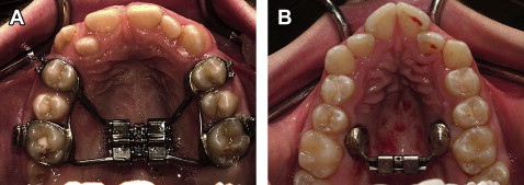
Subjects in the second group received a bone-anchored maxillary expander (BAME) composed of 2 custom-milled stainless steel onplants (diameter, 8 mm; height 3 mm), 2 miniscrews (length, 12 mm; diameter, 1.5 mm; Straumann GBR-System, Andover, Mass) and an expansion screw (Palex II Extra-Mini Expander, Summit Orthodontic Services, Munroe Falls, Ohio), shown in Figure 1 , B . This appliance was placed on each side between the projection of the permanent first molars and second premolar roots deep into the palatal vault and 6 mm from the suture. Before appliance placement, the patient was asked to rinse for 2 minutes with chlorhexadine (0.12%). This was followed by local anesthesia infiltration of the palatal mucosa between the first molars and second premolars. An 8-mm diameter tissue punch was used to make a circular incision. Tissue including the periosteum was removed, and the appliance was seated so that the onplant would have maximum direct contact with the bone surface of the palate. Guide drills were used to perforate the cortical plate of the bone, and miniscrews were placed to secure the appliance. Acrylic resin was used to seal the head of the screw to the stainless steel disc and prevent unwinding of the screw during appliance activation. Patients were prescribed oral antibiotics and chlorhexidine rinse for 5 days to prevent infection. A healing period of 1 week was allowed before activation of the expander. Activation consisted of 1 turn of the screw every other day until overcorrection was achieved. After active expansion, the retention protocol was the same as in the TAME group. Both groups had CBCT images taken 4 times (baseline [T1], after activation of the appliance [T2], after removal of the appliance [6 months, T3], and before fixed bonding [12 months, T4]).
The activation protocol differed between the treatment groups, since it was necessary to take precautions to prevent possible palatal shelf fracture for the bone-anchored appliance because this appliance is in a trial period. Tooth-anchored expanders followed the traditional protocol of 2 turns per day.
The subjects in the third group had treatment delayed for 12 months to serve as a control group. The delay of 1 year had no negative consequences regarding the patients’ treatment outcome. CBCT images were obtained for the control group at T1, T3, and T4.
Potential risks from radiation exposure with NewTom 3D images (Aperio Services, Verona, Italy) are minimal. For the 3D image, the radiation dose can be as low as 50 μSv, and the annual effective dose limit for infrequent exposure is 5 mSv.
All CBCT images were taken with the NewTom 3G device at 110 kV, 6.19 mAs, and 8-mm aluminum filtration. Images were converted to DICOM format by using the NewTom software to a voxel size of 0.25 mm. With AMIRA software (Mercury Computer Systems, Berlin, Germany), the DICOM-formatted images were rendered into volumetric images. Sagittal, axial, and coronal volumetric slices as well as the 3D reconstructions of the images were used for determining landmark positions. The landmarks we used are defined in Table II and shown in Figure 2 . Figure 3 gives an example of locating the middle of the pulp chamber of the maxillary first permanent molar in the 3 planes of space. The principal investigator (M.O.L.) located the landmarks on each image (10 images per day). Intraexaminer reliability of landmarks identification was determined by measuring 10 randomly selected images (3 times) 1 week apart. Digital spherical markers, 0.5 mm in diameter, were placed on the images to indicate the position of the landmark with the center of each marker in the exact location of the landmark. Linear distances between each landmark and its contralateral counterpart were used for analysis purposes. Distances, d , were determined by using the following equation.
Angles were determined by using the following equation.
a = A C O S ( d 1 ∗ d 1 + d 3 ∗ d 3 − d 2 ∗ d 2 ) / ( 2 ∗ d 1 ∗ d 3 )
with d1 , d2 , and d3 representing the 3 distances forming the triangle; their use depends on the location of the angle. Angle values were obtained in radians and converted to degrees by using the Excel spreadsheet function (Microsoft, Redmond, Wash).


