Clinicians worldwide are increasingly adopting guided surgical applications for dental implants. Clinicians are becoming more aware of the benefits of proper planning through advanced imaging modalities and interactive treatment planning applications. All aspects of the planning phase are based on sound surgical and restorative fundamentals. As an integral part of the implant team, dental laboratories have now moved from analog to the digital world, providing the necessary support to the new digital workflow.
Key points
- •
As technology continues to improve, and imaging modalities become widely available, clinicians worldwide are increasingly adopting guided surgical applications for dental implants.
- •
All aspects of the 3-D interactive treatment planning phase are based on sound surgical and restorative fundamentals.
- •
As an integral part of the implant team, dental laboratories have now moved from analog to the digital world, providing the necessary support to the new digital workflow.
- •
Guided surgery applications are dependent on careful diagnosis using the advanced tools that 3-dimensional imaging offers in combination with advanced interactive treatment planning software.
- •
Clinicians who wish to achieve true restoratively driven implant dentistry must be aware that the diagnostic phase often begins before the scan is taken.
- •
The use of diagnostic wax-ups, radiopaque scanning appliances, and the incorporation of intraoral optical scanners can significantly enhance the process and improve accuracy.
- •
The digital workflow is here to stay, providing clinicians with enhanced diagnostic tools for enhanced implant planning, surgical intervention, and links to computer-aided design software and computer-aided manufacturing process, and will continue to evolve over the next decade.
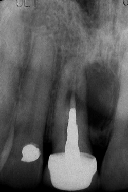
A 2-dimensional periapical radiograph has been the standard in dentistry for aiding clinicians in the diagnosis and treatment planning for various procedures including, but not limited to, the detection of dental caries, identifying pathology, periodontal disease, endodontic treatment, need for tooth extraction, and locating receptor sites for dental implants ( Fig. 1 ). However, periapical radiographs and panoramic radiology are inherently limited in the ability to accurately represent maxillomandibular structures. Two-dimensional radiography can only relate information about height or mesial-distal width but can not describe bone density, thickness of the cortical plates, or the true relationship of the natural tooth to the alveolar housing. When planning for dental implants, and especially when guided surgical applications are considered, it is essential that the true 3-dimensional anatomic presentation is understood and that all adjacent vital structures be accurately visualized.
The advent and acceptance of 3-dimensional computed tomography (CT), and newer-generation lower-dose cone beam CT scan devices (CBCT) in combination with interactive treatment planning software provides the clinicians with the ability to truly appreciate each patient’s anatomic reality. Regardless of the device used to acquire the dataset (CT vs CBCT), it is imperative that there is an understanding of how each image can provide important undistorted information that can be used for diagnosis and treatment planning for a variety of surgical and prosthetic interventions to improve accuracy and limit complications. Generally, the 3-dimensional dataset consists of 4 basic views: (1) the axial, (2) the cross-sections, (3) the panoramic reconstructed view, and the 3-dimensional reconstructed volume. Each of these views is important, as no one view alone should determine the ultimate desired treatment.
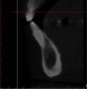
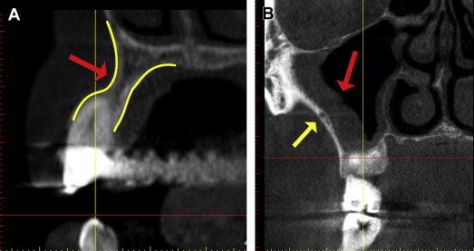
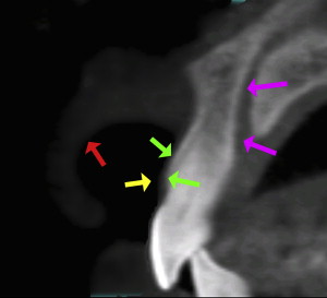
The cross-sectional view is important to help determine the quality of the bone, the thickness of the cortical plates, sinus pathology, periapical pathology, and the trajectory of the tooth within the alveolus. Often the natural tooth is positioned far to the facial or buccal of the alveolar bone ( Fig. 2 ). Therefore, when considering dental implant placement, clinicians can mistakenly try to position the implant within an extraction socket, which can result in less than satisfactory results. An appreciation of the cross-sectional image can aid clinicians in determining the topography of the alveolus, root morphology, and extent of any facial/buccal concavities ( Fig. 3 A ). If the site is critical for the planned reconstruction, then bone grafting procedures may need to be considered if there are bony defects present, often not detected by 2-dimensional imaging modalities. The posterior maxillary arch is another region in which cross-sectional imaging can provide anatomic details not visualized by any other means. The facial-palatal dimensions of the maxillary sinus can be fully appreciated, as can any sinus pathology or thickening of the Schneiderian membrane as seen in Fig. 3 B (red arrow). The thickness of the lateral sinus wall, and often vessels present within the lateral wall, can also be seen, in anticipation of a planned sinus augmentation procedure (yellow arrow). The placement of a simple cotton roll in the vestibule can add significantly to the diagnostic potential by lifting the lip from the alveolus (“lip-lift technique”), aiding in the appreciation of the bone, the vestibule, and the soft tissue, which is especially significant for the aesthetic zone of the maxillary sinus (red arrow in Fig. 4 ). The yellow arrow points to the thickness of the soft tissue covering the cortical bone (green arrows), and the cross-sectional view shows the path of the incisal nerve (magenta arrows). This diagnostic information is invaluable, improves accuracy of planning, and aids in the prevention of surgical and restorative complications.
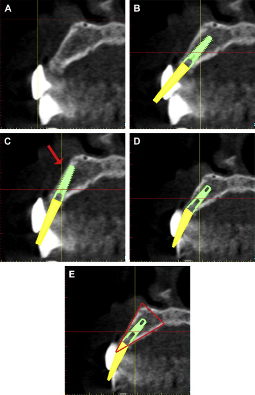
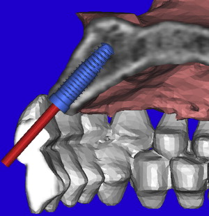
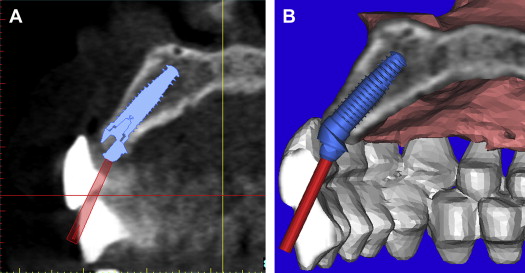
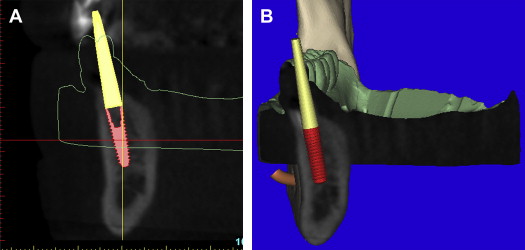
Before the acquisition of a CT or CBCT scan, it is often desirable to complete a diagnostic wax-up or a duplicate of the patient’s existing well-fitting denture to aid in restoratively driven planning. If a radiopaque material is used (Bariopaque, Salvin Dental Charlotte, NC), it will be visible on the scan, providing a link between the desired tooth position as it relates to the underlying bone ( Fig. 5 A ). The ability to visualize the tooth position greatly enhances treatment planning. Using an interactive treatment planning software application, a realistic implant can be virtually positioned within the cross-sectional alveolar bone (see Fig. 5 B). The yellow projection represents the path of the abutment, which, in this example, travels through the facial aspect of the tooth. This relationship would require an abutment to receive a cement-retained restoration. If a screw-retained restoration is desired, the apical end (arrow) of the implant must be rotated toward the facial cortical plate so that the abutment projection can emerge from the palatal or cingulum aspect of the tooth (see Fig. 5 C). This may result in a compromised volume of bone surrounding the implant and grafting may be required for long-term success. If the implant is placed so that the most volume of bone will surround the implant, an angulated abutment can be placed for either a cement-retained or screw-retained restoration (see Fig. 5 D). The author has designated this zone the “Triangle of Bone” as seen in Fig. 5 E. The Triangle of Bone defines an area allowing clinicians to analyze the bone within the triangle as a determinant for placement of an implant. To further appreciate the power of the diagnostic software, a slice through the 3-dimensional reconstructed volume illustrates a realistic implant with an abutment projection piercing through the desired tooth position as represented by the barium sulfate scanning template ( Fig. 6 ). If a screw-retained restoration will be the treatment plan of choice, an angled hex-engaging screw-receiving abutment must be used and can be simulated with a realistic abutment in the cross-sectional view and 3-dimensional reconstruction volumetric view ( Fig. 7 ).
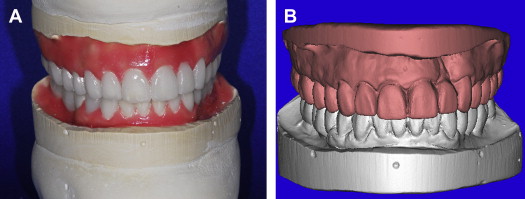
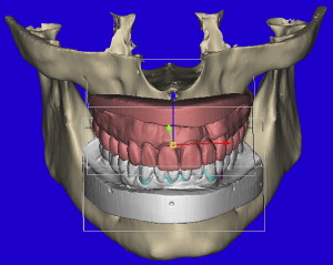
To facilitate the diagnosis process for guided surgery applications, and to maximize accuracy of the planning and template design, it is often desirable to have a diagnostic wax-up fabricated by the dental laboratory. This can be accomplished for a single tooth replacement, a full arch, or full mouth reconstruction. Alginate impressions are poured in stone, and delivered to the dental laboratory with a bite, for mounting with or without a facebow, depending on the needs of the case. The diagnostic wax-up is then fabricated to achieve the desired prosthetic outcome and can be used as a presentation/communication aid for the patient to gain case acceptance. This Master Diagnostic Model (MDM; Valley Dental Arts, Stillwater, MN) is examined for accuracy and bite relationship in all views ( Fig. 8 A ). The MDM is then placed into a desktop optical scanner to be digitized for use with the computer software applications (see Fig. 8 B). The software can also allow for virtual articulation similar to what has been used for conventional crown and bridge restorative dentistry in the fabrication of computer-aided design and computer-aided manufacturing (CAD CAM)–milled restorations. Advances in CT and CBCT interactive diagnostic software can provide additional links to further improve diagnostic accuracy, making it possible to integrate the standard triangulation language (STL) dataset from desktop or intraoral optical scanner devices. The models are imported into the software where they will be registered or “married” to the anatomic representations of the CT or CBCT axial and coronal slices. The models can then be further verified with the 3-dimensional volumetric views and the final positioning of the maxillary and mandibular STL models confirmed as superimposed to the CBCT dataset ( Fig. 9 ). The importance of merging these datasets can not be underestimated when planning dental implant surgery and is essential for certain template-guided surgical applications.
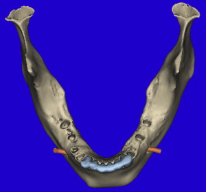
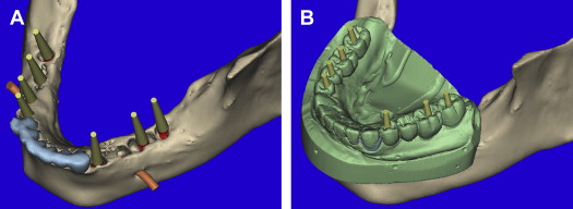
The 3-dimensional volumetric reconstructions of the mandibular arch ( Fig. 10 ) can aid in the visualization of the existing anterior teeth (blue), and an assessment of the posterior distal edentulous bony anatomy. The bilateral mental foramen and nerves can also be seen (orange). Implants can be planned for the posterior mandible, with yellow abutment projections showing the relative parallelism but without appreciation of where they will emerge within the desired occlusal scheme ( Fig. 11 A ). Once the MDM STL model was superimposed, the direction of the implants can be modified to fit within the envelope of the tooth position (see Fig. 11 B). The implant positions can be confirmed in all views, specifically within the alveolar bone of the cross-sectional image as related to the outline of the MDM STL model ( Fig. 12 A ). Further inspection using the clipping function of the interactive treatment planning software, provides state-of-the-art views of how the implant is represented within the bone and how the abutment projection (yellow) emerges from the occlusal aspect of the superimposed diagnostic model (see Fig. 12 B).
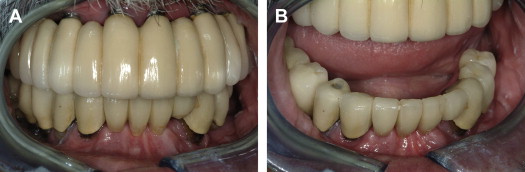
Case presentation
A 62-year-old man presented with a preexisting maxillary reconstruction and a lower failing reconstruction ( Fig. 13 ). The maxillary reconstruction needed replacement, as the vertical dimension of occlusion was compromised (overopened by 5.5 mm), making it difficult for the patient to function or speak properly. The panoramic view as reconstructed from the CBCT dataset shows the existing implants in the maxilla, and failing teeth supporting a fixed bridge in the anterior mandible, 3 existing posterior right mandibular implants supporting a separate fixed bridge, and a single implant located on the mandibular left side ( Fig. 14 ). The cross-sectional images representing the 3 mandible right implants were evaluated ( Fig. 15 ). Proximity of the existing implant to the mental foramen is seen in Fig. 15 C. The cross-sectional images of 2 of the remaining natural teeth confirm the circumferential bone loss around the roots ( Fig. 16 A, B ) and the proximity to the mental foramen on the left distal wide-diameter implant (see Fig. 16 C).