Introduction
The aims of this study were to analyze the stress distribution and displacement patterns that develop in an orthodontic miniscrew implant and its surrounding osseous structures for 2 implant materials under horizontal and torsional loading, with no ossseointegration.
Methods
A numeric approach was adopted. The finite element method was used to determine the stress and displacement of the various components at a given time after miniscrew implant application, when, due to viscoelastic relaxation effects, the only remaining stress field was from the application of the orthodontic load.
Results
Stress distribution was not significantly different between the 2 types of implant material. Increased stress values were located at the necks of the implants and the surrounding cortical bone. Bending of the titanium miniscrew was observed in the neck region under horizontal traction.
Conclusions
The differences between the values of stress and displacement we obtained for the 2 types of miniscrew were too small to be clinically significant. Optimization of the miniscrew implant composed of the titanium alloy might be achieved by increasing the bulk (quantity) of the material in the neck region. The miniscrew implant can be immediately loaded and used for group movement of teeth.
Recently, orthodontic miniscrew implants have been increasingly used in orthodontics because they offer additional advantages over the other types of anchorage mini-implants: their small size, ease of placement and removal, low cost, and the ability to be loaded immediately. A tapered variety of miniscrew implant with a sharp pyramidal apex has been developed to eliminate the need for a drill hole because it can be directly threaded into the bone. Most miniscrew implants are currently made of titanium alloy (Ti6Al4Vn, a mixture of titanium, 6 molecules of aluminum, and 4 molecules of vanadium; ASTM F 136); however, some continue to be made of implant-grade stainless steel (ASTM 316L), which is still used in traumatology.
Despite the many advantages of miniscrew implants, their clinical behavior is still unclear. Various authors have reported loosening and failure during clinical orthodontic treatment. Factors that have been reported to influence their retention are implant type, implant dimensions, implant surface characteristics, insertion angle, insertion torque, force magnitude, anatomic location, soft-tissue characteristics, root proximity, and primary stability. However, since these implants are intended to be loaded immediately, their primary stability is of the utmost importance. Good primary stability reduces the risk of micromotion and elicits a positive bone response in the form of increased bone remodeling. The bone remodeling process is correlated with the structural response of the surrounding bony tissues to the miniscrew implant and to the stress-strain field developing in the miniscrew implant itself.
Yano et al reported no significant difference when tapered miniscrews were loaded immediately or after a healing period of 6 weeks, suggesting that tapered miniscrews can be used for orthodontic anchorage immediately after their placement. Finite element studies on load transfer of miniscrew implants have been conducted by Dalstra et al and Gallas et al, who reported that areas of maximum stress were concentrated at the neck of the implant in the marginal bone. Gracco et al conducted a study to determine the effect of different lengths of miniscrew implants and the various osseointegration levels on their stability. They found that critical conditions occur for lengths of 14 mm with an orthodontic load of 2 N, and they preferred partial osseointegration (50%) over no osseointegration. Kim et al compared the stability between cylindrical and conical implant types and concluded that, although the conical mini-implant could induce tight contact to the adjacent bone tissue and produce good primary stability, the conical shape might need modification of the thread structure and the insertion technique to reduce the excessive insertion torque while maintaining its high resistance to removal.
A comprehensive analysis of the mechanical behavior of a conical self-drilling type of miniscrew implant and the response of the surrounding osseous structures to miniscrew implants composed of different materials and for different directions of force application has yet to be carried out. Studies of stress analysis allow optimization of the shape of the screw, the material of its composition, and its geometric parameters such as length, diameter, taper, and thread pitch. The aim of this research was to analyze the stress distribution patterns in a conical self-drilling type of miniscrew implant system and its surrounding osseous structures, with no ossseointegration, for 2 implant materials—Ti6Al4Vn alloy and implant-grade stainless steel—under horizontal and torsional loading. A numeric approach was adopted to investigate how the load transfer at the bone-screw interface changes for miniscrew implants made of different materials and for different directions of loading.
Material and methods
The finite element method is an advanced computer technique for structural stress analysis. It is used to obtain a solution to a complex mechanical problem by dividing the problem domain into a collection of a finite number of much smaller and simpler domains (elements): hence the term “finite element,” in which the field variables can be interpolated with the use of a shape function. This method in our study involved the following steps.
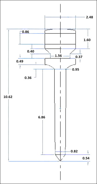
The purpose of constructing the geometric model was to represent the geometry in terms of points, lines, areas, and volumes. To build the screw model, the dimensions of an actual conical self-drilling miniscrew implant (S.K. Surgicals; Ambegaon, Pune, India) were measured by using a toolmaker’s microscope (Mitutoyo, Bangalore, India) with an accuracy of 10 μm. The length of the screw was 10.62 mm, with a threaded shaft 6.86 mm in length, and diameters of 2.48 mm at the head region, 0.95 mm at the upper end of the shaft, and 0.82 mm at the lower end of the shaft. The shaft of the miniscrew implant ended in a sharp pyramidal apex 0.54 mm in height. The number of threads was 1 per mm of length in the threaded region. The threads were arranged on the shaft in a spiral. The uppermost part of the head consisted of a rectangular slot with a width and a depth of 1 mm each, and a hole of 1-mm diameter was created in the center of the head. Measurements of other dimensions are given in Figure 1 . The length and diameter of the head, neck, and shaft were further confirmed by measurements made with a profile projector (Metzer Biomedical and Electronics, Wadala, Mumbai, India) with an accuracy of 10 μm. The dimensions obtained by the 2 methods were the same up to 2 decimal places. The thickness of the cortical bone considered for the analysis was 2 mm, and the inferior region consisted of cancellous bone. Dimensions taken from the measurements were used to build the 3-dimensional model by using the solid modeling software Pro/ENGINEER Wildfire (version 3; PTC, Needham, Mass). The 3-dimensional model was imported to finite element software (version 10; ANSYS, Canonsburg, Pa) by using the .iges format. In the geometric model, the osseous structures surrounding the miniscrew implant develop as a negative impression of the screw. The miniscrew implant model is placed in contact with the bone. Hence, no stresses appear in the assembly before external loading.
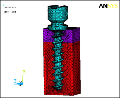
The geometric model was converted to the finite element model. The screw model called the domain was divided into smaller subdomains (elements) by a process known as discretization. It is essential that the elements do not overlap but are connected only at key points, termed nodes. The joining of elements at the nodes and the elimination of duplicate nodes is termed meshing. Figure 2 illustrates the cut-open meshed model and the negative impression of the miniscrew implant in the surrounding bone. The solid model is discretized by using the mesh generation tool of the software. The SOLID 92 element is used for the discretization. This is a quadratic element having 10 nodes, and each node has 3 degrees of freedom. The element also has plasticity, creep, swelling, stress, stiffness, and large deflection and strain capabilities. The numbers of nodes and elements for each part of the model (ie, the screw and the cortical and cancellous bones) are given in Table I .
| Elements | Nodes | |
|---|---|---|
| Cortical bone | 33,055 | 49,028 |
| Cancellous bone | 113,436 | 160,255 |
| Implant screw | 36,334 | 56,965 |
To simulate an approximate biologic condition, material properties were assigned to the relevant areas. Various components of the model are considered to be made up of isotropic materials that have identical physical properties along all 3 axes. The modulus of elasticity and Poisson’s ratio of the miniscrew implant materials (Ti6Al4Vn alloy [titanium alloy] and implant-grade stainless steel [stainless steel]) and the cortical and cancellous bones are provided in Table II . The values of the material properties used are the averages reported in the literature.
| Modulus of elasticity | Poisson’s ratio | |
|---|---|---|
| Titanium alloy | 110 GPa | 0.33 |
| Implant-grade stainless steel | 205 GPa | 0.29 |
| Cortical bone | 18 GPa | 0.3 |
| Cancellous bone | 13.7 GPa | 0.3 |
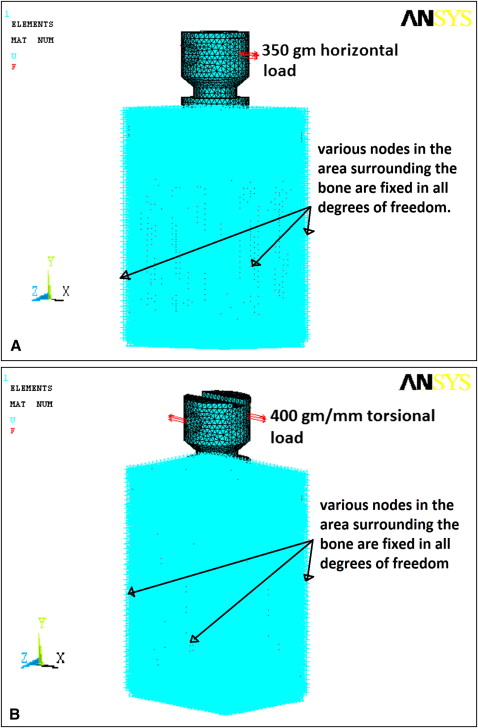
The boundaries of the finite element model were restricted in all 3 planes. This enabled us to study deformation on application of a load; without boundary restrictions, the body would behave like a free-floating rigid object and would undergo translatory or rotatory motion or both, without experiencing deformation. Two load conditions were considered: horizontal and torsional. The horizontal load was 350 g acting at the edge of the miniscrew implant head, perpendicular to its long axis. A torsional load of 400 g per millimeter was applied at the periphery of the head of the miniscrew implant at 2 points diametrically opposite to each other in a clockwise direction. Both loads were at the level of the eye of the screw meant for tying ligatures in a clinical situation. The loading and boundary conditions are illustrated in Figure 3 . The finite element model of the screw, with all the loading and boundary conditions, was then solved with the ANSYS software for the unknown variables: ie, the displacements and stresses at the nodes and the elements.
Results
The results of the analysis were viewed in the postprocessor of the analysis software. In this analysis, the miniscrew implant was the center of the study, and the materials (titanium alloy and stainless steel) were considered ductile. The Von Mises criterion was used to study the failure and distribution of stress in the miniscrew implants and the surrounding osseous structures. In the color band diagram showing stress distribution, the values are in newtons per square millimeter or megapascals. The axis of the screw is along the y-axis. The displacement due to torsional loading predominantly occurs in the y-axis direction; hence, the color plots are presented for the displacement in this direction. For horizontal loading, the displacement of the screw was predominantly in the x-axis direction. The dimensions of the model are in millimeters; therefore, the displacement values in the color band diagram are in millimeters. The stresses and displacements for the miniscrew implants and the cortical and cancellous bones were studied separately as well as collectively. The results were tabulated according to the areas of the model showing prominent and distinguishable stress and displacement patterns. These are shown in Tables III and IV .
| SSM | STM | DSM-x | DTM-x | DSM -y | DTM-y | |
|---|---|---|---|---|---|---|
| Screw | ||||||
| Upper third | 19.563 | 11.353 | 0.916 to 0.385 | – | 0.154 to −0.156 |
0.162 to −0.162 |
| Middle third | 4.349 | 3.785 | −0.400 | – | −0.0179 | −0.0544 |
| Lower third | 2.176 | 1.263 | 0.385 | – | 0.0165 | 0.0176 |
| Cortical bone | ||||||
| Vicinity of neck | 6.323 max 3.513 min |
6.466 max 5.747 min |
0.0876 | 0.0317 | 0.154 to −0.156 |
0.162 to −0.162 |
| Vicinity of flute | 1.405 | 1.437 | −0.0305 | −0.00992 | 0.0509 | 0.0536 |
| Cancellous bone | ||||||
| Boundary of cortical and spongy bones | 0.1744 | 0.175 max 0.136 min |
−0.0399 | −0.0238 | 0.0527 to −0.055 |
0.0536 to −0.0184 |
| Upper third | 0.1162 | 0.09741 | −0.0115 | −0.0377 | 0.0177 to −0.0174 |
0.0176 |
| Middle third | 0.01938 | 0.03897 | 0.00264 | 0.00397 | 0.00597 | 0.0176 |
| SSM | STM | DSM-y | DTM -y | |
|---|---|---|---|---|
| Screw | ||||
| Upper third | 17.272 | 8.719 | 0.00060 to −0.0010 |
0.00081 to −0.00091 |
| Middle third | 5.758 | 2.18 | −0.00011 | 0.00005 |
| Lower third | 1.92 | 1.09 | 0.00024 | 0.00024 |
| Cortical bone | ||||
| Vicinity of neck | 8.418 to 0.9353 | 8.539 to 0.948 | 0.00181 to −0.00192 |
0.00183 to −0.00194 |
| Cancellous bone | ||||
| Upper third | 0.0666 | 0.0462 | 0.00153 to −0.00178 |
0.00154 to −0.00175 |
| Lower third | 0.0074 | 0.0051 | 0.000431 | 0.000442 |
Stay updated, free dental videos. Join our Telegram channel
VIDEdental - Online dental courses


