The management of craniomaxillofacial (CMF) traumatic injuries can be challenging. Adequately restoring a patient to a preinjurious state of form and function can at times be vexing, even for the experienced surgeon. Over the last several decades, the advances in diagnostic imaging modalities and open reduction and internal fixation have contributed to improved success in the results of the CMF trauma patients. Concepts and algorithms that were introduced to restore the buttresses of the facial skeleton improved our understanding of the surgical management of the fractures . However, difficulty still exists in optimally reestablishing the CMF skeleton in three-dimensions (3D), resulting in facial asymmetry, when using traditional methods. This is particularly true in cases with panfacial injuries, or injuries involving areas with complex 3D anatomy (eg, orbit, zygomaticomaxillary complex).
Several factors may contribute to these suboptimal results . These include planning the surgery using two-dimensional (2D) imaging for complex 3D anatomy; poor direct visualization of the deep skeletal contours (eg, orbit, skull base); and difficulty visually assessing the intraoperative result for optimal position, projection, and symmetry.
Advances in technology have been incorporated into many different fields in medicine and dentistry, with neurosurgery being the pioneering discipline . Their uses in the surgical management of the CMF trauma patient can aid in improving the predictability and accuracy of the results. This article focuses on the application of the recent technological advancements in CMF trauma surgery.
Technology
The implementation of novel technological ideas to CMF trauma surgery can be divided into three broad categories: (1) computer-aided presurgical planning, (2) intraoperative navigation, and (3) intraoperative imaging .
The use of computer technology in the presurgical planning phase involves transferring CT scan data in a digital information and communications in medicine (DICOM) format into computer-aided design or computer-aided manufacturing (CAD-CAM) software, where the information can be analyzed and manipulated virtually in all three dimensions. A simulated surgical plan can then be performed through various methods, including mirror imaging the opposite, normal side; segmentation of the affected areas; virtual osteotomies; reduction of the affected bone in 3D space; or insertion of anatomic structures as needed. Furthermore, fabrication of stereolithographic models from data of the virtual reconstructions allows for preoperative plate contouring, planning of osteotomies, and facilitates the intraoperative contouring of bone grafts . Additionally, custom implants can be fabricated from the data, if necessary. Finally, the CAD-CAM software allows for conversion of the virtual reconstruction data back into DICOM format so that the information can be transferred to a surgical navigation system to be used intraoperatively Box 1 .
-
Amira (Berlin, Germany)
-
Analyze (AnalyzeDirect, Lenexa, Ann Arbor, MI, USA)
-
Intellect Cranial Navigation System (Stryker, Freiburg, Germany)
-
iPlan (BrainLab, Westchester, IL, USA)
-
Maxilim (Medicim, Bruges, Belgium)
-
MIMICS (Materialise, Leuven, Belgium)
-
Surgi Case CMF (Materialise, Leuven, Belgium)
-
Sim Plant OMS (Materialise Dental, Leuven, Belgium)
-
Voxim (IVS Solutions, Chemnitz, Germany)
-
3dMD (Atlanta, GA, USA)
The use of intraoperative navigation, or “frameless stereotaxy,” initially gained widespread use in neurosurgery . Subsequently, computer-assisted surgical navigation systems were introduced for use in the CMF region . These systems allow for accurate localization of anatomic points in 3D, with a margin of error less than 1 to 2 mm Box 2 .
-
Instatrak (General Electric Health Care, Buckinghamshire, UK)
-
Stealth Station (Medtronic-Xomed, Jacksonville, FL, USA)
-
Stryker Navigation System (Stryker-Leibinger, Kalamazoo, MI, USA)
-
Vector Vision (BrainLab, Westchester, IL, USA)
-
VoNaviX (IVS Solutions, Chemnitz, Germany)
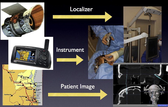
Intraoperative navigation has previously been described as being analogous to the global positioning system (GPS) systems used in automobiles . The basic components of the surgical navigation system includes a localizer, an instrument tracking probe, and CT scan data , as illustrated in Fig. 1 .
Certain navigation systems, such as the Instatrak, are based on a local electromagnetic platform to accurately localize the patient in space. These systems allow for a rapid intraoperative patient registration process; however, the local electromagnetic field can be disrupted by surrounding metallic or ferrous objects .
More contemporary navigation systems, such as Stryker and StealthStation, rely on an optical platform of light-emitting (infrared) diodes (LEDs) to track the patient and probe. This technology is independent of the electromagnetic field and its accuracy is not hindered by surrounding ferrous materials. A direct line of sight must be maintained between the LEDs on the patient and the infrared sensor or localizer .
To accurately define the spatial relation of the instrument probe on the real patient to the virtual images, the computer must be able to convert between the coordinate systems of the patient, instrument probe, localizer, and data . Thus, the use of intraoperative navigation begins with the registration (spatial correlation) process. Registration allows for an accurate, intraoperative correlation between the virtual patient on the monitor (CT scan images) to the real patient on the operating table. There are invasive and noninvasive methods to complete the registration process. Invasive registration involves the placement of screws into the patient’s head, either extraorally (eg, calvarium) or intraorally (maxilla). The main disadvantage of this technique is that it requires a surgical procedure to insert the screws. Noninvasive techniques include the use of adhesive skin markers, anatomic landmarks, and occlusal splints. The adhesive skin marker method is simple, has high accuracy, and is the authors’ primary choice. The use of anatomic landmarks leads to poor reproducibility and, therefore, is not commonly used in CMF trauma cases anymore. Another registration method is termed “surface matching,” which is a markerless technique whereby multiple points on the patient’s surface are scanned and correlated with CT scan data. This process can yield good accuracy if performed on large, curvy bone surfaces, such as the scalp, if a coronal incision is used for surgical access.
Once the registration process is completed between the patient and the image data set, the initial spatial correlation between the patient, probe, localizer, and CT scan images is defined and further changes in position of any of these factors can be accurately calculated .
The use of intraoperative CT scanning can help improve in the postoperative results. With the newer technology, one can instantaneously reconstruct the axial images to coronal, sagittal, and 3D images. This permits the surgeon to acquire real-time knowledge of the reconstructed bony skeleton and make any refinements or adjustments in the same operative setting.
Surgical repair of panfacial fractures
The steps involved in the secondary repair of a patient with severe, panfacial injuries are described to illustrate the use of various technological tools in the surgical management of panfacial fractures ( Figs. 2–12 ).
Stay updated, free dental videos. Join our Telegram channel
VIDEdental - Online dental courses


