The pivotal point in treatment planning for dental implants occurs when the location of bone is viewed radiographically in the context of the planned prosthesis. Radiographic planning for dental implant therapy should be used only after a review of the patient’s systemic health, imaging history, oral health, and local oral conditions. The radiological diagnostic and planning procedure for dental implants can only be fully achieved with the use of a well-designed and -constructed radiographic guide. This article reviews several methods for construction of radiographic guides and how they may be utilized for improving implant surgery planning and performance.
Key points
- •
The use of volumetric imaging is emerging as a valued aid in planning, placement, and restoration of dental implants.
- •
Any cone beam computed tomography (CBCT) scan intended for these purposes must include a scan prosthesis or integrate an optical scan of a diagnostically waxed cast. When the assembled 3-dimensional model (segmented maxilla, mandible, and prostheses) is visualized, available planning software enables improved planning and enhanced communication.
- •
The planned treatment can be used to direct computer aided design – computer aided manufacture fabrication of surgical guides that offer 3-dimensional control of implant placement.
- •
Ongoing development enables clinicians to design and manufacture patient-specific abutments within this 3-dimensional virtual environment to further streamline and improve planning and treatment.
- •
Clinicians should understand fully the advantages of this technology to appropriately prescribe CBCT scanning for dental implant treatment planning and therapy.
Introduction
Successful dental implant therapy occurs with the congruent achievement of osseointegration and the location of implants to ideally support the intended restoration. The pivotal point in treatment planning for dental implants occurs when the location of bone is viewed radiographically in the context of the planned prosthesis. As suggested for any other radiographic diagnostic modality, radiographic planning for dental implant therapy should be used only after a review of the patient’s systemic health, imaging history, oral health, and the local oral conditions. It is of further importance to emphasize that the radiological diagnostic and planning procedure for dental implants can only be fully achieved with the use of a well-designed and -constructed radiographic guide. It is the intent of this article to review several methods for construction of radiographic guides and how they may be utilized for the improvement of implant surgery planning and performance.
Volumetric imaging
Cone beam computed tomography (CBCT) has become the prominent method of generating 3-dimensional radiographic images in dentistry. The CBCT scanner produces a cone-shaped radiograph beam that exposes a series of planar images as the focused radiograph beam processes in a circular path around the patient. The computer assembles these multiple images in 3-dimensional volume that can be reoriented to meet the viewing need of the clinician. Although similar in concept to a medical CT scan, the radiation dose is much less, and tailored fields of view offer further dose reduction aligned with the ALARA (as low as (is) reasonably achievable) principles of radiation hygiene and safety. The use of CBCT for dental implant planning has been carefully debated, and several recommendations have been made. For example, the American Dental Association Council on Scientific Affairs recently published an advisory statement on the use of CBCT in dentistry. It is advised that CBCT imaging should be used only after a review of the patient’s health and imaging history and the completion of a thorough clinical examination. CBCT imaging should be prescribed only when it is expected that the diagnostic yield will benefit patient care, enhance patient safety, or improve clinical outcomes significantly. There are many situations involving the potential dental implant patient in which these guidelines apply.
The main advantage of CBCT imaging is that a 3-dimensional image of the osseous region of interest may be constructed and viewed in multiple planes. Planning that leads to implant placement results in a reasonable level of accuracy as suggested by a recent systematic review. With regard to osseous architecture, the ability to visualize anatomic landmarks is high. Less clear is the value of CBCT images to accurately estimate or define the density of bone. The quality of the CBCT image may be a limiting factor affecting planning. Although not the objective of this article, it is important to highlight relevant factors that reduce the diagnostic and planning qualities of the CBCT image. An obvious factor is motion-related artifacts that cause blurring. Because the resolution of the machines is typically less than 0.3 to 0.5 mm, even small patient movements create problems. Another factor is the scatter that may be produced from metallic restorations in the mouth, and, unfortunately in CBCT, the streak artifacts occur in all directions. Beam hardening occurs when the beam is attenuated as it passes through dense objects (included dental implants), making the related areas less diagnostic. Noise reduces the ability to resolve features of close radiodensities, and in CBCT imaging, lower power (mA) is one reason for this. The continued development of computational solutions and hardware design suggests progressive improvement in CBCT images for dental implant planning.
Recent guidelines for prescription of CBCT imaging for dental implant treatment planning have been suggested by multiple organizations ( Box 1 ).
- •
Evaluate the morphology of the residual alveolar ridge
- •
Determine the orientation of the alveolar ridge
- •
Identify anatomic features that could limit the implant fixture position
- •
Evaluate pathologic conditions that would restrict the implant fixture placement
- •
Match imaging findings to the restorative plan
- •
It should be considered when preoperative cross-sectional imaging is deemed required
- •
CBCT is desired when there is a need for hard tissue grafting
- •
It should be used to evaluate hard tissues after augmentation procedures have been performed
Computer-aided implant planning and implant placement have been developed to allow for more efficient preoperative assessment of bone volume and safe implant placement with adequate consideration for a successful implant restoration outcome. Treatment planning by virtual 3-dimensional implant placement is based on both anatomic and prosthetic considerations and criteria. Inclusion of volumetric imaging in this process is the only way to fully appreciate the position of the implant in 3 dimensions. However, without inclusion of the planned tooth or prosthesis position in this 3-dimensional image, such planning is not possible. A central aspect of computer-aided implant planning using radiographic volumetric images is the use of radiographic stents that present the planned tooth or prosthesis position within the radiographic image.
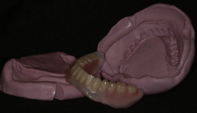
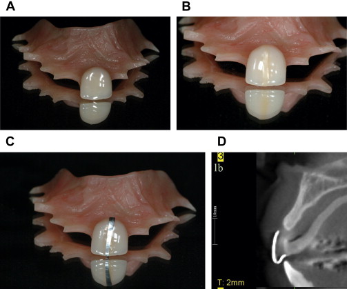
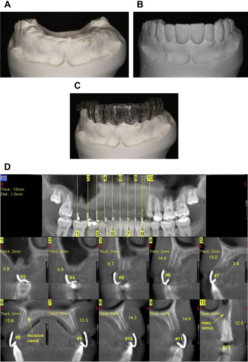
The ideal features of a radiographic stent are listed in Box 2 . There are many different ways to produce a useful radiographic stent. At least 4 different approaches should be available to clinicians to accommodate the broad array of different clinical circumstances. They include (1) use of an existing prosthesis containing radiopaque markers or fiduciaries ( Fig. 1 ), (2) use of a thermoplastic shim incorporating radiopaque markers ( Fig. 2 ), (3) use of radiopaque teeth in a mucosa or tooth-supported stent ( Fig. 3 ), or (4) fabrication of a radiopaque resin duplicate of a prosthesis or a diagnostic wax-up ( Fig. 4 ).
-
Radiopaque indicator of correct tooth form and position without inducing scatter
-
Retentive and stable intraorally
-
Comfortable
-
Sterilizable, if used as a surgical guide
-
Compatible with scanner (hardware) platform
The use of an existing prosthesis as a radiographic stent (and possibly a surgical guide) is simple, direct, and cost-effective. A prerequisite for this is that the position of the tooth or teeth in the existing prosthesis represents the intended position of the future implant-related prosthesis. In such cases, all that is required is the placement of radiopaque markers or fiduciaries onto or within the prosthesis to achieve the scan. Immediately following scanning, the markers may be removed (see Fig. 1 ).
When considering the other 3 approaches, a similar clinical course of action is needed. All 3 procedures require that preliminary study casts are mounted on an articulator. Next, in all cases, the planned position and form of the proposed prosthesis must be defined by denture tooth arrangement or diagnostic waxing methods. This is true of single-tooth, multiple-tooth (eg, implant-supported fixed dental prosthesis), or full arch restorations.
Use of a thermoplastic shim incorporating radiopaque markers is a relatively inexpensive and rapid method of creating a radiographic stent that embodies the ideal features enumerated previously (see Fig. 2 ). Following the establishment of tooth position (often verified clinically by a wax try-in or temporization), the diagnostically waxed study cast is duplicated in laboratory plaster (or snap stone). The cast is trimmed to display only the alveolar ridge and teeth of the maxilla or mandible to enable rapid trimming of the plastic material. The estimated or desired location of implant(s) is marked on the cast by drawing a line bisecting the intended tooth mesiodistally. Sticky wax is applied to this line, and a 0.5 mm wide strip of lead foil (obtained from radiographic film packets) is applied to this position by rubbing with a warm wax spatula. It is important that the lead foil extend from the midlingual position to the buccal cervical margin of the designated tooth. The cast, now decorated with lead foil strips in the estimated location of implants, is placed onto the vacuformer platform, and a thermoplastic shim is formed directly onto the cast. The heat from the resin typically transfers both the wax and the lead foil to the inner surface of the formed thermoplastic shim. The shim can be trimmed to the height of contour of the majority of teeth, which enables ease of placement with sufficient stability during scanning and subsequent surgery. It is advantageous to trim the shim to the cervical contour of the planned implant restoration to permit estimation of implant depth. For single-tooth implants, a thin material of 0.5 to 0.75 mm can be used. However, as the extent of the edentulous area expands, a thicker material (eg, 2.0 mm Biocryl [Great Lakes Orthodontics, Tonawanda, NY, USA]) can be used to prevent flexing of the stent intraorally. For distal extension situations, even thicker materials can be used (eg, 3.0 mm Biocryl) to avoid distortion or flexing.
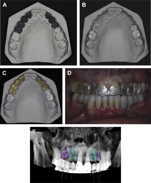
The use of radiopaque teeth to create a surgical guide offers the advantage of displaying the complete 3-dimensional form of the tooth in the CBCT-generated volumetric image (see Fig. 3 ). The process for creating this type of guide again begins with the accurate mounting of diagnostic study casts. Here, the radiopaque teeth are adapted and placed onto the cast to represent the position of the planned implant-related prostheses with acknowledgment of the estimated position of the planned implant(s). There are at 3 three ways of incorporating the radiopaque teeth into the radiographic stent. The first follows the process described herein for the thermoplastic shim and by vacuum forming; the radiopaque teeth are retained within the stent (see Fig. 4 ). It is useful to utilize an acrylic material (eg, 0.75 mm Clear Splint Biocryl). The second way involves the use of composite baseplate material (eg, Triad [Dentsply International, York, PA, USA]) and requires hand forming of the tooth-supported guide using strips of this material adapted to the natural teeth and incorporating the radiopaque teeth within the formed guide. A third method is the processing of the radiopaque teeth into either a removable or complete prosthesis (see Fig. 3 ). When confronted with extensive edentulous regions of an arch or complete edentulous arches, the inclusion of tissue bearing flanges adds to the stability and accuracy of the radiographic stent. When adopting this approach, the processed acrylic resin will be radiolucent unless a radiopaque alternative (eg, Biocryl X) is used in the processing of the stent. A radiopaque stent is necessary when mucosal surgical guides are utilized or when generating a plan by segmentation methods.
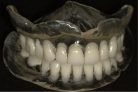
For many situations involving partial edentulism and complete edentulism, where the eventual treatment plan will involve an implant-supported partial or complete overdentures, or will result in full arch prosthesis for the edentulous patient, it is often advantageous to complete the waxing of the partial or complete overdenture to verify phonetics, esthetics, and function. In taking full advantage of this strongly recommended diagnostic approach, another way of creating a radiographic template is by means of duplicating the partial or complete denture in a radiopaque resin (see Fig. 5 ). Two divergent scanning procedures are possible here. One is an integrated scan that requires the denture to be duplicated in a radiopaque resin (eg, Biocryl X). The radiopaque denture is worn during the CBCT scanning procedure. The duplication of a denture is readily performed in a duplicating flask or by using silicone putty in a clam shell technique ( Fig. 5 ). The second approach is the dual scan technique, in which the dentures are scanned by CBCT, and the patient wearing the dentures is scanned by CBCT. Here, the denture must bear radiopaque (and geometrically) identifiable fiduciary markers (4–6) distributed throughout the denture so that the denture may be aligned with the patient following the scanning procedure ( Fig. 6 ). Some advantages of the dual scan technique include that the manipulation of the volumetric images is reduced in the process of generating a digital plan and the digital manufacture of a surgical guide.