Introduction
To provide information about placement sites and angulations of microimplants between tooth roots, we analyzed 3-dimensional computed tomography images from 25 patients.
Methods
The patients in the sample had good interdigitation, no restorations, and no arch length discrepancies in the posterior segments. Three-dimensional images of the maxillary and mandibular second premolars, first molars, and second molars were constructed. The distances and midpoints between the roots at 3 levels were calculated, and the angles between the lines connecting the midpoints and perpendicular lines to the occlusal plane at the contact points were also calculated.
Results
The midpoints between the roots were located distally to the contact point and from the cervical to the apical areas. The lines connecting these midpoints from the cervix to the apex of the roots in the mandibular arch had more distal inclination than in the maxillary arch.
Conclusions
To minimize root contacts, microimplants need to be inclined distally about 10° to 20° and placed 0.5 to 2.7 mm distally to the contact point to minimize root contact according to sites and levels, except into palatal interradicular bone between the maxillary first and second molars.
The dental implants that have been used as orthodontic anchorage provide reliable anchorage for uncompliant patients. However, they have disadvantages: high cost, long waiting time for osseointegration, and extensive surgical procedure. Most importantly, their bulky size limits placement into retromolar and midpalatal areas. Therefore, they need to be connected to the teeth to be used as anchorage.
Important advancements in microimplants and mini-implants were achieved in the last decade. Creekmore and Eklund placed a miniscrew under the anterior nasal spine to intrude the maxillary incisors, and Kanomi placed microscrews in the chin to intrude the mandibular incisors. The reason for placing miniscrews or microscrews below the apex of the roots might be to reduce the chance of root damage. However, mini-implants or microimplants placed below the roots might not produce horizontal force but, rather, intrusive force. Park placed microscrews between the roots of maxillary second premolars and first molars to retract the maxillary anterior teeth, and observed distal movement of the whole dentition. By placing the microimplants between the roots, the horizontal component of force could be increased. However, there was concern about root contacts during placement and tooth movement.
To reduce root contacts, Park and Park et al placed microimplants in an oblique direction buccolingually, 30° to 40° to the long axis of the teeth in the maxillary posterior area and 10° to 20° in the mandibular posterior area. However, there were also requirements for angulating the microimplants mesiodistally to follow the curvature of the roots.
Factors affecting the stability of microimplants are host, surgical, and management. Among these, the surgical factor might be the most important because microimplants failed most often within 3 months after placement.
According to a recent study, microimplants placed close to the roots, as seen in radiographs, had a higher failure rate. Therefore, it is important to understand the shape and curvature of the roots. Surgical guides can be used to minimize root contacts. However, a contact point on a crown is usually used as the reference point to indicate the midpoint of the roots. Understanding the point of placement anteroposteriorly relative to the contact point and the angulation is important when placing microimplants.
The purpose of this study was to provide information on placement sites and angulation of microimplants between the roots by measuring the midpoints between roots at 3 levels and the direction of root curvature by using computed tomography (CT) images.
Material and methods
The sample included 25 patients (14 men, 11 women; ages, 18-32 years; average age, 25.6 years) who had good interdigitation and buccal occlusion, no restorations, and no arch-length discrepancy in the posterior segments. They were patients who visited a dental clinic in Daegu, Korea, in order to extract a third molar. Dental CT images for assessing the position and direction of the third molars were taken in 2006 and 2007.
Dental CT images were taken with a cone-beam dental CT (V Seoul, Korea), and slice thickness was 1 to 1.5 mm. The CT data were transformed to DICOM 3.0 files and stored on a personal computer. The 3-dimensional (3D) images of the maxillary and mandibular second premolars, first molars, and second molars were constructed with CB Works (version 2.1, Cybermed, Seoul, Korea).
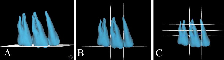
The plane connecting the 3 points—the buccal cusp of the second premolars, the mesiolingual cusp of the first molars, and the mesiobuccal cusp of the second molars—was used as the horizontal reference plane ( Fig 1 , A ). Two vertical reference planes were constructed. The vertical planes were at a right angle to the horizontal plane at the contact points of the crowns of adjacent teeth ( Fig 1 , B ). The 3 additional lines parallel to the horizontal plane were drawn at 3 vertical levels: cervical (2-3 mm apical to the cementoenamel junction), middle (5-6 mm apical to the cementoenamel junction), and apical (8-9 mm apical to the cementoenamel junction) ( Fig 1 , C ).
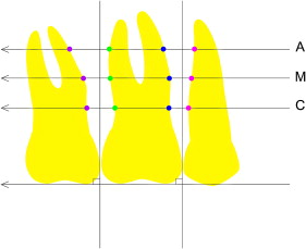
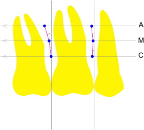
The distances between the roots were measured at 3 vertical levels: cervical, middle, and apical ( Fig 2 ). In the maxilla, the distances between roots were measured on the buccal and palatal sides; the distances were measured only on buccal side in the mandible. The shortest distances from the buccodistal line angle at the root of the front tooth to the buccomesial line angle at the root of the adjacent back tooth were measured. On the palatal side, the shortest distances from the palatodistal line angle of the root to the palatomesial line angle of the adjacent tooth root were measured. The midpoints between the roots were marked, and the distances from the midpoints to the vertical reference planes passing the contact points of the crowns were measured ( Fig 3 ). The angles between the lines connecting the midpoints marked at the 3 vertical levels and the vertical reference lines were calculated ( Fig 3 ).
Statistical analysis
The statistical analysis was performed with SAS software (version 8.02, SAS Institute, Cary, NC). The positions of the midpoints relative to the contact point between the crowns were measured, and the angles between the lines connecting the midpoints and the perpendicular lines to the horizontal reference lines were also calculated. There was no statistical difference in these parameters between the sexes, which were combined for convenience of statistics. A 1-way analysis of variance (ANOVA) and the Scheffé multiple comparison post-hoc test were used to compare the differences in distances between the roots and the positions of the midpoints relative to the vertical reference lines at the various sites and levels.
To test reliability, 3D images were reconstructed at the left side, and all parameters were measured again 2 weeks later. Interclass correlations showed statistically significant reliability in all measurements ( P >0.05).
Results
The means and standard deviations of the measurements were calculated. The distance between the roots of the second premolars and first molars was wider than that between the first and second molars in the maxilla ( P <0.001). In the mandible, the space between the first and second molars was wider than that between the second premolars and first molars but not statistically significant. The interradicular spaces increased from the cervical to the apical levels, except for the middle level of buccal interradicular space between the maxillary first and second molars ( P <0.001) ( Tables I and II ).
| 5-6 (buccal) | 6-7 (buccal) | 5-6 (palatal) | 6-7 (palatal) | P value | |
|---|---|---|---|---|---|
| Cervical | 3.21 ± 0.78 | 2.88 ± 0.63 | 3.62 ± 0.79 | 3.64 ± 0.86 | <0.001 |
| Middle | 3.69 ± 0.70 | 2.45 ± 0.89 | 4.53 ± 1.23 | 4.27 ±1.04 | <0.001 |
| Apical | 3.87 ± 0.84 | 3.81 ± 1.60 | 5.14 ± 1.13 | 5.39 ± 1.36 | <0.001 |
| P value | <0.001 | <0.001 | <0.001 | <0.001 |
| 5-6 (buccal) | 6-7 (buccal) | P value | |
|---|---|---|---|
| Cervical | 3.03 ± 0.51 | 3.23 ± 0.75 | <0.131 |
| Middle | 3.20 ± 0.72 | 3.57 ± 1.17 | <0.055 |
| Apical | 3.84 ± 0.89 | 4.06 ± 1.33 | <0.319 |
| P value | <0.001 | <0.001 |
The midpoints of the interradicular spaces were located distal relative to the vertical reference plane, passing the contact points of the crown ( P <0.001) ( Tables III and IV ). The midpoints at the apical level were located more distal compared with the cervical and middle levels because the roots of the teeth curved distally. The midpoints of the palatal interradicular space between the maxillary first and second molars were located distally and even more distally at the apical level ( P = 0.022) but close to the vertical reference line compared with other sites.
| 5-6 (buccal) | 6-7 (buccal) | 5-6 (palatal) | 6-7 (palatal) | P value | |
|---|---|---|---|---|---|
| Cervical | –0.90 ± 0.38 | –0.47 ± 0.44 | –1.05 ± 0.38 | –0.27 ± 0.44 | <0.001 |
| Middle | –1.22 ± 0.52 | –1.35 ± 0.64 | –1.70 ± 0.81 | –0.41 ± 0.61 | <0.001 |
| Apical | –1.95 ± 0.75 | –2.05 ± 0.74 | –2.80 ± 0.55 | –0.63 ± 0.83 | <0.001 |
| P value | <0.001 | <0.001 | <0.001 | 0.022 |
| 5-6 (buccal) | 6-7 (buccal) | P value | |
|---|---|---|---|
| Cervical | –0.41 ± 0.41 | –0.51 ± 0.51 | <0.300 |
| Middle | –0.51 ± 0.46 | –1.64 ± 0.64 | <0.001 |
| Apical | –1.07 ± 0.68 | –2.77 ± 0.68 | <0.001 |
| P value | <0.001 | <0.001 |
The lines connecting the midpoints inclined distally from the cervical to the apical levels ( Table V ). The distal angulations were higher at the middle apical level than at the cervical middle level in all areas except the buccal interradicular space between the maxillary first and second molars. The greatest distal inclinations were observed at the palatal interradicular areas between the second premolars and first molars in the maxilla and the buccal interradicular area between the first and second molars in the mandible.


