This article describes a modified technique for indirect bonding. Crucial variables that influence the procedure are analyzed and discussed to help the clincian use the indirect bonding techinique routinely.
Orthodontists use the indirect bonding technique to enhance accuracy in bracket positioning. Brackets are positioned on a cast and then successively transferred to the patient’s mouth via customized trays. The indirect technique saves time in the office and reduces the patient’s discomfort compared with direct techniques. No differences in accuracy or shear bond strength were found between direct and indirect procedures; however, fewer mistakes (smaller range values) were observed when using the indirect technique.
Many kinds of indirect bonding procedures have been proposed; some are characterized by the type of tray (eg, silicone, thermal glue, rapid prototyped ), type of adhesion system (eg, light curable ), or type of bracket-positioning guide (eg, slot heights ).
Despite the availability of several proposed indirect techniques, the indirect procedure is not yet the gold standard, probably because of numerous procedural variables that must be controlled to obtain successful indirect bonding. The aim of this article was to present a modified, standardized indirect bonding technique for routine and effective use of the indirect bonding procedure.
This indirect bonding technique is performed in 3 stages.
-
In-office stage
- 1.
Using heavy-bodied alginate, take impressions of both arches. Use the blue hard dental stone to make the casts; after they are dried, clean them and remove the defects.
- 2.
Make the bracket-positioning guide on the model ( Fig 1 ) as follows: using a black pencil, mark the facial axis of the clinical crown, overcoming the gingival margin, and, using a red pencil, mark the labial projection of the marginal ridges of the first and second premolars and the first molars; then, measure the clinical crown heights with a caliper and calculate the slot heights according to the method of McLaughlin et al. Using a black-pencil gauge, mark the slots on the incisors, canines, and molars; use a caliper to calculate the distance between the molar slot ( Fig 1 , black line ) and its marginal ridge ( red line ); reproduce this distance on both the second and the first premolars, marking the slots.
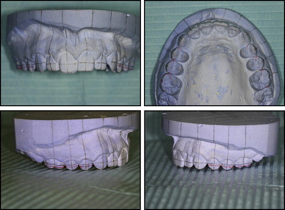
Fig 1 The bracket-positioning guide on the model. - 3.
Deliver both the cast and the appliance to a laboratory technician trained in the following technique.
-
In-laboratory stage
- 4.
Apply a layer of separating agent (Unifol; Perident Dental Products, Florence, Italy; Fig 2 ) on the tooth surfaces with a brush and permit the cast to dry fully.
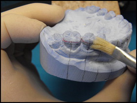
Fig 2 Application of the separating agent. - 5.
Put a light-curable composite adhesive (Transbond; 3M Dental Products, St Paul, Minn) on each bracket base, press firmly on the tooth surface, and remove any excess ( Fig 3 ). Position each bracket, aligning its slot and its axis to the marked slot and to the marked facial axis of the clinical crown. Once the positioning on the full arch is finished, light-cure the adhesive in a dedicated machine (Fotolab UV; Tissi Dental, Milan, Italy).
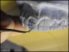
Fig 3 Positioning of the bracket according to the bracket-positioning guide. - 6.
Using a thin layer of translucent soft silicone (Emiluma; Opal Orthodontics, South Jordan, Utah), cover the brackets labially and occlusally ( Fig 4 ), allow it to harden, and remove any excess silicone; thermo-form a 1-mm thick rigid tray on the arch (Erkopress ES-200E; Erkodent, Pfalzgrafenweiler, Germany; Fig 5 ) and trim the disc, creating 2 palatal ears on the last tooth of each side; allow it to cover the premolar labial cuspids, the canines tips and the incisor edge in the rest of the arch ( Fig 6 ). Labially, cut the tray at the slot level, permitting the silicone to cover the entire bracket.
Fig 4 Application of the translucent soft silicone to make the soft layer of the tray.Fig 5 Disc thermo-forming to make the rigid tray.Fig 6 Rigid tray refinement to give the desired tray shape. - 7.
Soak the model in water for 30 minutes and then gently debond the brackets from the model ( Fig 7 ); clean the residual stone and separating agent with 50-μm size sand in a dedicated machine (Uno; Tissi Dental) at 1 bar of pressure, and then wash the transfer tray with a toothbrush and soap, rinse, and dry fully.
Fig 7 Removing the tray with a scalpel.
-
In-laboratory stage
- 4.
Apply a layer of separating agent (Unifol; Perident Dental Products, Florence, Italy; Fig 2 ) on the tooth surfaces with a brush and permit the cast to dry fully.


