Introduction
Our aim was to evaluate which anchorage system is better suited for both anteroposterior and vertical anchorage control of maxillary posterior teeth.
Methods
Fifty-one subjects requiring maximum anchorage were divided into 2 groups according to maxillary posterior anchorage reinforcement: high-pull headgear, conventional transpalatal arch, and interarch elastics (n = 28); or modified transpalatal arch supported by 2 midpalatal miniscrews (n = 23). Bilateral maxillary first premolars were extracted in all patients. Pretreatment and posttreatment lateral cephalometric radiographs were superimposed to compare skeletal and dental changes between the groups.
Results
(1) The miniscrew group had less mesial movement of the maxillary first molars (0.85 vs 3.63 mm) and greater maxillary incisor retraction (6.87 vs 4.50 mm) than did the headgear group with the same treatment duration. (2) The maxillary molars were significantly intruded in the miniscrew group (1.30 mm), whereas they were extruded in the headgear group (0.71 mm). In the miniscrew group, intrusion of the maxillary molars resulted in a statistically significant decrease in the mandibular plane angle (0.80°). Patients using high-pull headgear showed no significant decrease in these measurements.
Conclusions
In both the anteroposterior and vertical directions, a modified transpalatal arch supported by 2 midpalatal miniscrews provided more stable anchorage.
It is no exaggeration to state that anchorage control in edgewise treatment is the most important factor that affects the treatment plan and the results, especially for high-angle patients whose chief complaint is upper lip protrusion. In adults, such major orthodontic treatment plans require premolar extractions and maximum anchorage.
Traditionally, extraoral or intraoral appliances such as high-pull headgear and interarch elastics were used to help maintain the anchorage of the maxillary posterior teeth. However, high-pull headgear has inherent disadvantages associated with patient noncompliance, duration of wear, unacceptability by many adults, and potential risk of injury. Furthermore, although interarch elastics are effective in correcting the anteroposterior relationships of the dentition, some undesirable side effects can occur. Many authors have noted adverse results because of the vertical force vector that is inherent with interarch elastics. This vertical force can cause teeth to extrude and lead to an opening rotation of the mandible.
Since the advent of temporary anchorage devices or skeletal anchorage devices, miniplates and miniscrews have been used to obtain skeletal anchorage without patient cooperation, with promising results. Many case studies have reported that buccal miniscrews, used as direct anchorage, allow the anterior teeth to be retracted effectively without anchorage loss. However, root contact of buccal miniscrews is considered a primary reason for their failure when placed in interdental areas. Interdental miniscrews can also act as a mechanical interference that limits adjacent tooth movement. Therefore, the removal and replantation of miniscrews are required in certain cases.
Sites for miniscrews should be carefully selected to minimize root movement interference and the number of replantation procedures. To prevent root contact of miniscrews and to decrease failure rates, nondental-bearing areas such as the midpalatal area of the maxilla have been reported to be good sites for miniscrew implantation. Moreover, the midpalatal suture is a highly dense structure with sufficient bone height up to the cresta nasalis, ensuring biomechanical stability of the midpalatal miniscrews. In addition, the covering soft tissue is keratinized; this is beneficial in minimizing inflammation in the midpalatal area. Its thickness is consistent at 1 mm, enough to support midpalatal miniscrews. However, other mediating appliances are required because the midpalatal suture area is far from the teeth that the clinician aims to control. Various attempts have been made to use miniscrews as skeletal anchorage in the midpalatal suture area. In this study, the combination of 2 midpalatal miniscrews with a modified transpalatal arch was used as a skeletal anchorage system to reinforce anchorage of the maxillary posterior teeth both anteroposteriorly and vertically.
The null hypothesis was that there would be no significant differences in anchorage losses of the maxillary posterior teeth between the miniscrew group (skeletal anchorage system) and the high-pull headgear group (traditional anchorage system) when treating patients with maxillary dentoalveolar protrusion and a hyperdivergent facial type. The purposes of this retrospective study were to compare the skeletal and dental changes in subjects treated with 2 anchorage systems with the same orthodontic mechanics and to evaluate which anchorage system is better suited for both anteroposterior and vertical anchorage control of the maxillary posterior teeth.
Material and methods
The clinical records of consecutively treated patients from 2008 to 2011 were searched to identify appropriate subjects. The patients had undergone level anchorage system treatment at Aichi-Gakuin University Dental Hospital in Nagoya, Japan. A total of 51 subjects met the following inclusion criteria: (1) Angle Class II Division 1 or Class I malocclusion with bimaxillary protrusion, (2) hyperdivergent skeletal pattern, (3) well-aligned maxillary incisors with minimal crowding (≤3.5 mm), (4) full permanent dentition (except for the third molars), and (5) extraction of bilateral maxillary first premolars (with various strategies for the mandibular arch, including nonextraction or extraction of the first or second premolars). All subjects were successfully treated (ie, Class I or full-cusp Class II molar relationship, Class I canine relationship, and adequate overbite and overjet were obtained). The exclusion criteria were (1) poor film quality or incomplete records, (2) patients who received skeletal anchorage in the mandible and midpalatal areas, (3) patients with major rotations or a posterior crossbite, (4) prolonged use of vertical seating elastics during the finishing stage, and (5) patients with congenital malformations, systemic diseases, or syndromic conditions.
The subjects were characterized by maxillary dentoalveolar protrusion and a hyperdivergent skeletal pattern. The treatment plan involved maximum maxillary incisor retraction in addition to vertical dimension control. In these patients, both the anteroposterior and vertical control of the maxillary posterior anchorages were of major importance. The subjects were divided into 2 groups according to the type of maxillary posterior anchorage reinforcement ( Table I ).
| Headgear group | Miniscrew group | P value | Significance | |
|---|---|---|---|---|
| Subjects (n) | 28 | 23 | ||
| Sex (male/female) | 6/22 | 0/23 | ||
| Initial age (y) | 19.61 ± 7.43 | 21.50 ± 6.19 | 0.334 | NS |
| Treatment duration (mo) | 36.89 ± 10.12 | 34.75 ± 7.48 | 0.404 | NS |
The high-pull headgear group included 28 subjects who received traditional anchorage reinforcement with high-pull headgear, conventional transpalatal arch, and interarch elastics. After the initial leveling and aligning in the maxillary arch, maxillary posterior anchorage was reinforced with high-pull headgear, and Class III elastics were used for anchorage preparation to upright the mandibular molars. After stabilization of the mandibular arch, high-pull headgear and Class II elastics were used during the maxillary en-masse retraction. All subjects were instructed to wear the high-pull headgear for 10 to 12 hours per day throughout the treatment period and to record their headgear wear time on daily charts. A force of approximately 250 g on each side was applied at the level of the buccal trifurcation (center of resistance) of the maxillary first molars. The importance of wearing the extraoral appliance as anchorage was explained at the initial stage and reiterated throughout active treatment.
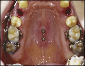
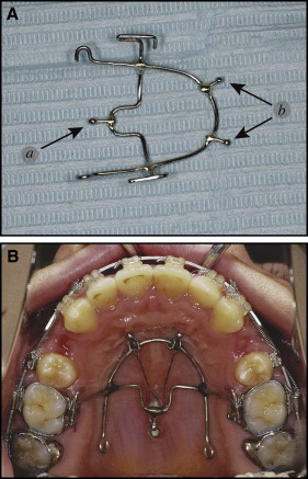
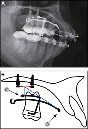
The miniscrew group consisted of 23 subjects who received implantation of 2 self-drilling miniscrews (Induce MS-II; GC Ortholy, Tokyo, Japan; diameter, 1.8 mm; length, 6.0 mm; and Dual-Top Anchor; Jeil Medical, Seoul, Korea; diameter, 2.0 mm; length, 6.0 mm) in the midpalatal suture. The miniscrews were inserted under local anesthesia between the mesiolingual cusps (center of the occlusal surface) of the maxillary first molars and those of the maxillary second molars. To reduce soft-tissue inflammation around the miniscrews, strict instructions regarding oral hygiene were given to the subjects. After 2 weeks of healing, the 2 midpalatal miniscrews were connected with a horizontal 0.030-in stainless steel ligature wire ( Fig 1 ). The horizontal ligature wire provided support where the vertical ligature wires were firmly tied, enabling them to fasten a modified transpalatal arch ( Figs 2 and 3 ). Intrusion was performed with either elastomeric chains or ligature wires from the horizontal ligature wire to the stabilization hook of the modified transpalatal arch. The stabilization hook was used to prevent mesial tipping of the posterior teeth and to apply intrusive force to the posterior teeth. Ideally, the modified transpalatal arch should be positioned 5 to 7 mm from the depth of the palate to prevent impingement of the arch on the tissues when an intrusive force is applied to the maxillary molars. When a long action range of the intrusion action components was needed, the horizontal ligature wire and lingual sheathes of the molar bands were connected with longer elastomeric chains. While the maxillary molars were being intruded, the modified transpalatal arch was also used to prevent palatal tipping of the maxillary molars.
All midpalatal miniscrews achieved primary stability. However, 3 (1 in each of 3 subjects) of the 46 total midpalatal miniscrews became mobile during the en-masse retraction, for a success rate of 93.48%. In the failed cases, a hairpin-shaped wire was bent to fit the head part of the remaining sound miniscrew passively; this provided support instead of a horizontal ligature wire. Treatment was continued with 1 remaining sound miniscrew. Therefore, the failed cases can be considered to have had a limited influence on the results.
All subjects were treated with preadjusted edgewise appliances, 0.018 × 0.025-in slot, level anchorage system prescription brackets (3M Unitek, Monrovia, Calif). We applied the same treatment protocol in both groups with 1 exception: the method of anchorage reinforcement. After the initial leveling and aligning in the maxillary arch, stabilizing transpalatal arches were needed to control the posterior segments. Therefore, we added stabilizing (conventional or modified) transpalatal arches in both groups. Maxillary posterior anchorage was reinforced with high-pull headgear or miniscrew-supported modified transpalatal arches in each group. Once the clinicians were satisfied that the anchorage reinforcement was secure, the bilateral maxillary first premolars were extracted. In both groups, 6 maxillary anterior teeth were retracted on a 0.017 × 0.025-in nickel-titanium archwire with 0.010 × 0.036-in stainless steel closed-coil springs that were stretched two-thirds of the distance from the maxillary first molars to the crimpable hooks located mesial to the canines. Gable bends of 45° were placed in the extraction sites to prevent tipping of the maxillary incisors lingually during the en-masse retraction. When the extraction space measured 2 to 3 mm, a 0.018 × 0.025-in stainless steel archwire with keyhole loops was used for root control in the extraction sites, torque control of the maxillary anterior teeth, and final space closure. The keyhole loops were activated 1 mm at a time. Anchorage reinforcement was continued until the extraction space was closed. When the mandibular arch was stabilized and the maxillary canines were in a Class I relationship with the mandibular canines, the patients were instructed to stop wearing the high-pull headgear, or the midpalatal miniscrews were disconnected from the modified transpalatal arch. Stabilizing (conventional or modified) transpalatal arches were also removed in both groups. In the finishing phase, after removing only the posterior segments of the 0.018 × 0.025-in stainless steel finishing archwires, laced posterior vertical elastics were applied for better interdigitation of the occlusion; these remained in place for 2 to 3 weeks at the most.
Lateral cephalometric radiographs, obtained routinely within 1 month before treatment and immediately after removal of the fixed appliances, were taken in centric occlusion. The images were then hand-traced on matte cephalometric acetate tracing film by the orthodontists in charge (M.T., M.S., M.K.) and verified by another orthodontist (K.M.). Tracings were made through the midpoints between the right and left structures, and the measurements were adjusted to eliminate radiographic magnification. All radiographs were taken anonymously by obscuring any patient data.
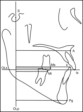
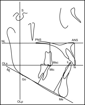
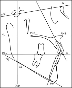
To evaluate changes between the pretreatment and posttreatment data and to compare treatment changes between the 2 groups, skeletal and dental changes were calculated according to the method described by Pancherz. In several recent studies, the dentofacial morphology of subjects with maxillary dentoalveolar protrusion was compared using the Pancherz cephalometric analyses. The Pancherz approach comprises sagittal occlusal analysis and vertical occlusal analysis ; the use of these 2 methods enables differentiation between sagittal and vertical dentofacial problems, as well as associated changes. The cephalometric landmarks and reference lines for Pancherz’s sagittal, vertical, and angular analyses are shown in Table II and Figures 4 through 6 .
| Ii (incison inferius) | The incisal tip of the most prominent mandibular incisor |
| Is (incison superius) | The incisal tip of the most prominent maxillary incisor |
| Mi (molar inferius) | The mesial contact point of the mandibular first permanent molar by a tangent parallel to OLp |
| Mic | The mesiobuccal cusp tip of the mandibular first molar |
| Ms (molar superius) | The mesial contact point of the maxillary first permanent molar by a tangent parallel to OLp |
| Msc | The mesiobuccal cusp tip of the maxillary first molar |
| Pg (pogonion) | The most anterior part of the bony chin determined by a tangent parallel to OLp |
| A | The deepest point on the anterior contour of the maxillary aleveolar projection determined by a tangent parallel to OLp |
| N | Nasion |
| S | Sella |
| ANS | Anterior nasal spine |
| PNS | Posterior nasal spine |
| Me | Menton |
| Go | Gonion |
| Is-OLp–Ii-OLp | Overjet |
| Ms-OLp–Mi-OLp | Molar relationship |
| A-OLp | Maxillary base position |
| Pg-OLp | Mandibular base position |
| A-OLp–Pg-OLp | Jaw-base relationship |
| Is-OLp | Maxillary central incisor position |
| Ii-OLp | Mandibular central incisor position |
| Is-OLp–A-OLp | Maxillary central incisor relationship to A-point |
| Ii-OLp–Pg-OLp | Mandibular central incisor relationship to Pg |
| Ms-OLp | Maxillary first permanent molar position |
| Mi-OLp | Mandibular first permanent molar position |
| OLp | Occlusal plane perpendicular, reference line perpendicular to OLs through S |
| Ii-OLs | Overbite, the distance Ii perpendicular to OLs |
| ANS-Me | Lower face height |
| Is-NL | Maxillary central incisor position, the distance Is perpendicular to NL |
| Ii-ML | Mandibular central incisor position, the distance Ii perpendicular to ML |
| Msc-NL | Maxillary first permanent molar position, the distance of Msc perpendicular to NL |
| Mic-ML | Mandibular first permanent molar position, the distance of Mic perpendicular to ML |
| NL/NSL | Nasal plane angle, the angle between the maxillary plane (ANS-PNS) and the N-S plane (NSL) |
| ML/NSL | Mandibular plane angle, the angle between the mandibular plane (Me-Go) and the N-S plane (NSL) |
| OLs/NSL | Maxillary occlusal plane angle, the angle between the maxillary occlusal plane and the N-S plane (NSL) |
| OLi/NSL | Mandibular occlusal plane angle, the angle between the mandibular occlusal plane and the N-S plane (NSL) |
| NL | Nasal line (maxillary plane) |
| ML | Mandibular line (mandibular plane) |
| NSL | Nasal sella line |
| OLs | Maxillary occlusal plane |
| OLi | Mandibular occlusal plane |
Statistical analyses
All statistical analyses were performed with SPSS software (version 15.0; SPSS, Chicago, Ill). For each variable, the mean and standard deviation values were calculated, and the levels of statistical significance were P <0.05, P <0.01, and P <0.001. The Kolmogorov-Smirnov method was used to confirm the normal distribution of the measurements. The distribution of the data was found to be normal; therefore, parametric statistics were applied.
For both groups, the pretreatment measurements of the radiographs from each group were assessed using an independent-samples t test to check for pretreatment equivalence. A paired-samples t test was used to determine the significance of the treatment changes in both skeletal and dental positions from the pretreatment and posttreatment radiographs in each group. Treatment changes in the skeletal and dental positions between the 2 groups were compared with an independent-samples t test.
All cephalometric measurements were repeated by the same examiner (J.L.) 4 weeks later. The repeated measurements were assessed with a paired-samples t test for systematic errors. No variable had statistically significant systematic errors ( P >0.05). The greatest mean differences between the first and second readings for all linear and angular measurements did not exceed 0.5 mm and 0.5°, respectively. The mean values were used in the statistical analysis. An intrarater reliability analysis with the weighted kappa statistic was performed to determine consistency. The weighted kappa statistic for the repeated readings showed the highest value of 0.96 for Is-OLp and the lowest value of 0.87 for the SNB angle. There was almost perfect agreement between all measurements.
Results
There were no statistically significant differences in initial ages and treatment durations between the 2 groups ( P >0.05) ( Table I ). The effect of any residual growth and treatment periods on treatment changes could be expected to be similar.
Pretreatment differences in the variables for the groups are shown in Table III . For the sagittal measurements, A-OLp, Is-OLp, and Ms-OLp were used to compare the anteroposterior amounts of skeletal and dental changes according to maxillary posterior anchorage. These parameters represented the anteroposterior position of the maxillary base, the maxillary central incisor, and the maxillary first permanent molar, respectively. The pretreatment anteroposterior position showed no significant differences between the 2 groups ( P >0.05). The pretreatment axial inclination of the maxillary incisor showed no significant difference ( P >0.05). However, overjet, molar relationship, jaw relationship, and ANB angle were significantly greater in the miniscrew group. These results suggested that this group would have greater anteroposterior discrepancies in skeletal and dental relationships. For the vertical measurements, an independent t test showed no significant differences for any variable between the groups.
| Parameter | Headgear group | Miniscrew group | P value | Significance | ||
|---|---|---|---|---|---|---|
| Mean | SD | Mean | SD | |||
| Sagittal measurements | ||||||
| Overjet (mm) | 4.86 | 3.52 | 6.85 | 3.06 | 0.038 | ∗ |
| Molar relationship (mm) | −2.54 | 2.38 | −0.04 | 1.88 | 0.000 | † |
| Position of maxillary base (mm) | 79.13 | 4.05 | 79.80 | 4.16 | 0.559 | NS |
| Position of mandibular base (mm) | 82.11 | 5.27 | 79.70 | 7.74 | 0.212 | NS |
| Jaw relationship (mm) | −2.98 | 3.84 | 0.11 | 4.60 | 0.012 | ∗ |
| Position of maxillary central incisor (mm) | 92.02 | 4.52 | 92.98 | 3.77 | 0.421 | NS |
| Position of mandibular central incisor (mm) | 87.16 | 5.83 | 86.13 | 4.77 | 0.499 | NS |
| Maxillary central incisor relationship to A-point (mm) | 12.89 | 2.95 | 13.17 | 2.37 | 0.714 | NS |
| Mandibular central incisor relationship to Pg (mm) | 5.05 | 3.70 | 6.43 | 5.64 | 0.299 | NS |
| Position of maxillary first permanent molar (mm) | 58.75 | 3.88 | 60.57 | 4.54 | 0.130 | NS |
| Position of mandibular first permanent molar (mm) | 61.29 | 5.14 | 60.61 | 4.96 | 0.637 | NS |
| SNA (°) | 81.36 | 2.74 | 82.63 | 3.11 | 0.127 | NS |
| SNB (°) | 77.55 | 3.98 | 75.54 | 3.36 | 0.060 | NS |
| ANB (°) | 3.80 | 2.11 | 7.09 | 2.26 | 0.000 | † |
| Angulation of maxillary central incisor (°) | 108.32 | 11.58 | 105.61 | 12.44 | 0.425 | NS |
| Angulation of mandibular central incisor (°) | 98.93 | 6.67 | 102.41 | 7.07 | 0.077 | NS |
| Interincisal angle (°) | 114.18 | 9.57 | 111.65 | 13.03 | 0.429 | NS |
| Vertical measurements | ||||||
| Overbite (mm) | 1.93 | 2.15 | 2.39 | 3.80 | 0.607 | NS |
| Lower facial height (mm) | 73.77 | 4.39 | 75.76 | 7.08 | 0.247 | NS |
| Position of maxillary central incisor (mm) | 31.34 | 2.72 | 32.85 | 3.05 | 0.068 | NS |
| Position of maxillary first permanent molar (mm) | 25.48 | 2.12 | 25.22 | 2.60 | 0.690 | NS |
| Position of mandibular central incisor (mm) | 46.68 | 2.60 | 48.00 | 3.36 | 0.120 | NS |
| Position of mandibular first permanent molar (mm) | 37.11 | 2.60 | 37.54 | 3.05 | 0.584 | NS |
| Nasal plane angle (°) | 10.25 | 3.07 | 8.83 | 3.24 | 0.114 | NS |
| Mandibular plane angle (°) | 37.41 | 6.27 | 39.46 | 8.11 | 0.315 | NS |
| Maxillary occlusal plane angle (°) | 20.39 | 4.55 | 22.39 | 5.59 | 0.165 | NS |
| Mandibular occlusal plane angle (°) | 16.55 | 5.60 | 17.59 | 7.08 | 0.563 | NS |
Table IV shows the skeletal and dental changes in each group and compares the changes between the groups. For each cephalometric parameter, changes between pretreatment and posttreatment in each group are listed and compared with the associated P values, as determined by the paired-samples t test. An increase in the measurement was expressed as a positive value; a decrease was expressed as a negative value. Positive values indicated extrusion, mesial movement, or crown anterior and root posterior angular changes; negative values indicated intrusion, distal movement, or crown posterior and root anterior angular changes.
| Parameter | Headgear group | Miniscrew group | Headgear group vs miniscrew group | |||||||||||||
|---|---|---|---|---|---|---|---|---|---|---|---|---|---|---|---|---|
| Pretreatment | Posttreatment | Difference | P value | Significance ∗ | Pretreatment | Posttreatment | Difference | P value | Significance ∗ | P value | Significance † | |||||
| Mean | SD | Mean | SD | Mean | SD | Mean | SD | |||||||||
| Sagittal measurements | ||||||||||||||||
| Overjet (mm) | 4.86 | 3.52 | 3.07 | 0.66 | −1.79 | 0.012 | ‡ | 6.85 | 3.06 | 3.04 | 1.83 | −3.80 | 0.000 | ¶ | 0.047 | ‡ |
| Molar relationship (mm) | −2.54 | 2.38 | −2.23 | 2.64 | 0.30 | 0.371 | NS | −0.04 | 1.88 | −0.28 | 3.34 | −0.24 | 0.645 | NS | 0.364 | NS |
| Position of maxillary base (mm) | 79.13 | 4.05 | 79.14 | 4.11 | 0.02 | 0.935 | NS | 79.80 | 4.16 | 79.20 | 3.89 | −0.61 | 0.002 | § | 0.033 | ‡ |
| Position of mandibular base (mm) | 82.11 | 5.27 | 82.98 | 5.52 | 0.88 | 0.105 | NS | 79.70 | 7.74 | 79.78 | 8.07 | 0.09 | 0.831 | NS | 0.254 | NS |
| Jaw relationship (mm) | −2.98 | 3.84 | −3.84 | 4.42 | −0.86 | 0.083 | NS | 0.11 | 4.60 | −0.59 | 5.38 | −0.79 | 0.118 | NS | 0.806 | NS |
| Position of maxillary central incisor (mm) | 92.02 | 4.52 | 87.52 | 4.33 | −4.50 | 0.000 | § | 92.98 | 3.77 | 86.11 | 4.52 | −6.87 | 0.000 | ¶ | 0.003 | § |
| Position of mandibular central incisor (mm) | 87.16 | 5.83 | 84.45 | 4.35 | −2.71 | 0.000 | ¶ | 86.13 | 4.77 | 83.07 | 4.64 | −3.07 | 0.000 | ¶ | 0.697 | NS |
| Maxillary central incisor relationship to A-point (mm) | 12.89 | 2.95 | 8.38 | 2.77 | −4.52 | 0.000 | ¶ | 13.17 | 2.37 | 6.91 | 2.22 | −6.26 | 0.000 | ¶ | 0.016 | ‡ |
| Mandibular central incisor relationship to Pg (mm) | 5.05 | 3.70 | 1.46 | 3.61 | −3.59 | 0.000 | ¶ | 6.43 | 5.64 | 3.28 | 4.76 | −3.15 | 0.000 | ¶ | 0.606 | NS |
| Position of maxillary first permanent molar (mm) | 58.75 | 3.88 | 62.38 | 4.16 | 3.63 | 0.000 | ¶ | 60.57 | 4.54 | 61.41 | 4.80 | 0.85 | 0.034 | ‡ | 0.000 | ¶ |
| Position of mandibular first permanent molar (mm) | 61.29 | 5.14 | 64.61 | 5.41 | 3.32 | 0.000 | ¶ | 60.61 | 4.96 | 61.70 | 5.48 | 1.09 | 0.073 | NS | 0.004 | § |
| SNA (°) | 81.36 | 2.74 | 81.02 | 2.73 | −0.34 | 0.004 | § | 82.63 | 3.11 | 82.02 | 2.79 | −0.61 | 0.012 | ‡ | 0.253 | NS |
| SNB (°) | 77.55 | 3.98 | 77.36 | 3.98 | −0.20 | 0.407 | NS | 75.54 | 3.36 | 75.26 | 3.65 | −0.28 | 0.212 | NS | 0.792 | NS |
| ANB (°) | 3.80 | 2.11 | 3.66 | 2.17 | −0.14 | 0.565 | NS | 7.09 | 2.26 | 6.76 | 2.18 | −0.33 | 0.214 | NS | 0.609 | NS |
| Angulation of maxillary central incisor (°) | 108.32 | 11.58 | 100.32 | 10.05 | −8.00 | 0.001 | ¶ | 105.61 | 12.44 | 96.30 | 9.31 | −9.30 | 0.001 | ¶ | 0.683 | NS |
| Angulation of mandibular central incisor (°) | 98.93 | 6.67 | 95.55 | 8.71 | −3.38 | 0.030 | ‡ | 102.41 | 7.07 | 100.39 | 9.41 | −2.02 | 0.235 | NS | 0.543 | NS |
| Interincisal angle (°) | 114.18 | 9.57 | 127.43 | 8.54 | 13.25 | 0.000 | ¶ | 111.65 | 13.03 | 124.33 | 9.12 | 12.67 | 0.001 | ¶ | 0.880 | NS |
| Vertical measurements | ||||||||||||||||
| Overbite (mm) | 1.93 | 2.15 | 1.57 | 0.49 | −0.36 | 0.386 | NS | 2.39 | 3.80 | 1.65 | 0.57 | −0.74 | 0.373 | NS | 0.677 | NS |
| Lower facial height (mm) | 73.77 | 4.39 | 74.46 | 4.74 | 0.70 | 0.123 | NS | 75.76 | 7.08 | 75.26 | 7.13 | −0.5 | 0.188 | NS | 0.047 | ‡ |
| Position of maxillary central incisor (mm) | 31.34 | 2.72 | 31.89 | 3.38 | 0.55 | 0.072 | NS | 32.85 | 3.05 | 31.30 | 3.53 | −1.54 | 0.023 | ‡ | 0.005 | § |
| Position of maxillary first permanent molar (mm) | 25.48 | 2.12 | 26.20 | 2.02 | 0.71 | 0.001 | ¶ | 25.22 | 2.60 | 23.91 | 2.60 | −1.30 | 0.000 | ¶ | 0.000 | ¶ |
| Position of mandibular central incisor (mm) | 46.68 | 2.60 | 44.86 | 3.19 | −1.82 | 0.000 | ¶ | 48.00 | 3.36 | 45.39 | 4.47 | −2.61 | 0.000 | ¶ | 0.181 | NS |
| Position of mandibular first permanent molar (mm) | 37.11 | 2.60 | 38.89 | 2.58 | 1.79 | 0.000 | ¶ | 37.54 | 3.05 | 39.07 | 3.23 | 1.52 | 0.000 | ¶ | 0.466 | NS |
| Nasal plane angle (°) | 10.25 | 3.07 | 10.34 | 3.09 | 0.09 | 0.259 | NS | 8.83 | 3.24 | 8.89 | 3.05 | 0.07 | 0.328 | NS | 0.818 | NS |
| Mandibular plane angle (°) | 37.41 | 6.27 | 37.05 | 7.06 | −0.36 | 0.337 | NS | 39.46 | 8.11 | 38.65 | 8.28 | −0.80 | 0.021 | ‡ | 0.374 | NS |
| Maxillary occlusal plane angle (°) | 20.39 | 4.55 | 22.63 | 5.30 | 2.23 | 0.001 | ¶ | 22.39 | 5.59 | 25.52 | 6.47 | 3.13 | 0.014 | ‡ | 0.496 | NS |
| Mandibular occlusal plane angle (°) | 16.55 | 5.60 | 19.05 | 5.24 | 2.50 | 0.010 | § | 17.59 | 7.08 | 22.02 | 6.60 | 4.43 | 0.001 | ¶ | 0.177 | NS |
Stay updated, free dental videos. Join our Telegram channel
VIDEdental - Online dental courses


