Introduction
The purpose of this research was to evaluate microdamage accumulation after mini-implant placement by self-drilling (without a pilot hole) and self-tapping (screwed into a pilot hole) insertion techniques. The null hypothesis was that the mini-implant insertion technique would have no influence on microcrack accumulation and propagation in the cortical bones of the maxillae and mandibles of adult hounds.
Methods
Mini-implants (n = 162; diameter, 1.6 mm; length, 6 mm) were placed in the maxillae and mandibles of 9 hounds (12-14 months old) with self-drilling and self-tapping insertion techniques. The techniques were randomly assigned to the left or the right side of each jaw. Each hound received 18 mini-implants (10 in the mandible, 8 in the maxilla). Histomorphometric parameters including total crack length and crack surface density were measured. The null hypothesis was rejected in favor of an alternate hypothesis: that the self-drilling technique results in more microdamage (microcracks) accumulation in the adjacent cortical bone in both the maxilla and the mandible immediately after mini-implant placement. A cluster level analysis was used to analyze the data on the outcome measured. Since the measurements were clustered within dogs, a paired-samples t test was used to analyze the average differences between insertion methods at both jaw locations. A significance level of 0.05 was used for both analyses.
Results
The self-drilling technique resulted in greater total crack lengths in both the maxilla and the mandible (maxilla: mean difference, 18.70 ± 7.04 μm/mm 2 ; CI, 13.29-24.11; mandible: mean difference, 22.98 ± 6.43 μm/mm 2 ; CI, 18.04-27.93; P <0.05), higher crack surface density in both the maxilla and the mandible (maxilla: mean difference, 10.39 ± 9.16 μm/mm 2 ; CI, 3.34-17.43; mandible: mean difference, 11.28 ± 3.41 μm/mm 2 ; CI, 8.65-13.90; P <0.05).
Conclusions
This study demonstrated greater microdamage in the cortical bones of adult hounds in both the maxilla and the mandible by the self-drilling insertion technique compared with the self-tapping technique.
Mini-implants have gained enormous popularity in orthodontics and are now considered sources for absolute osseous anchorage. Their primary advantages are simple surgical insertion and removal, placement at numerous anatomic locations, economic viability, and minimal need for patient compliance. However, before the use of a mini-implant for orthodontic anchorage, it is necessary to ensure adequate stability. The success or failure of an implant largely depends on the degree to which it integrates with the host bone. Overall, the success of mini-implants is guided by the physical, chemical, and biologic events at the bone-implant interface. The initial stability of the mini-implant at its placement is determined by the quality and quantity of bone at the implant site, the geometry of the implant, and the method of site preparation. Because bone quality and volume are determined by local (patient) factors, the initial stability of the fixture is primarily influenced by the implant design and the placement technique.
Mini-implants can be inserted by either the self-tapping or the self-drilling technique. Self-tapping requires predrilling of a pilot hole followed by screwing in of the implant body. This technique has some inherent disadvantages, particularly for interradicular areas, such as damage to adjacent tooth roots, drill-bit breakage, and, most importantly, thermal necrosis of the surrounding bone. Necrosis of the bone contributes to osteolysis around the implant and loss of stability. On the other hand, the self-drilling procedure is simpler, allowing insertion of the mini-implant into bone without predrilling for most clinical applications. In spite of this advantage, if the bone is dense or the screw diameter is large with a tapered shape, excessive placement torque can cause overcompression of the cortical bone, leading to microdamage. Microdamage is a permanent deformation of the microstructure of loaded cortical bone in the form of fatigue and creep, and manifests histologically as microcracks that are discontinuities of the calcium-rich bone matrix around implants. It has been suggested that microcracks initiate “targeted remodeling,” wherein osteoclasts target and remove the region of bone matrix that has sustained the microdamage, and osteoblasts replace the area with new bone.
Although a few studies have reported the effects of diameter and shape of mini-implants on microdamage to the cortical bone and on the stability of self-drilling and self-tapping implants, no study has evaluated the microdamage accumulation in the cortical bone after mini-implant placement by different placement techniques. Moreover, studies involving some kind of loading force to the implants can affect the early microdamage, making it difficult to differentiate the effect of implantation methods from that of loading forces on the bone. Therefore, the purpose of this in-vivo study was to evaluate microdamage accumulation in the cortical bone of the maxillae and the mandibles of adult hounds, immediately after mini-implant placement, by the self-drilling (without pilot hole) and self-tapping (predrilled pilot hole) insertion techniques. The null hypothesis was that mini-implant insertion technique would have no influence on microcrack accumulation and propagation in the cortical bones of the maxilla and the mandible of the hounds. It was our intention to create evidence for clinicians regarding a better insertion technique for mini-implants.
Material and methods
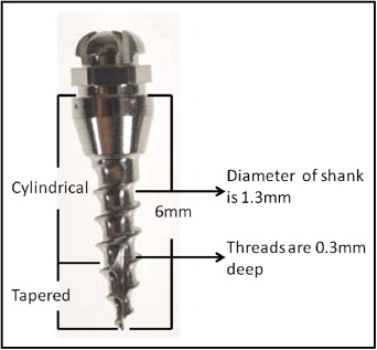
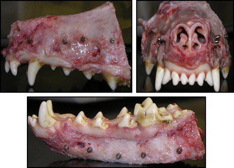
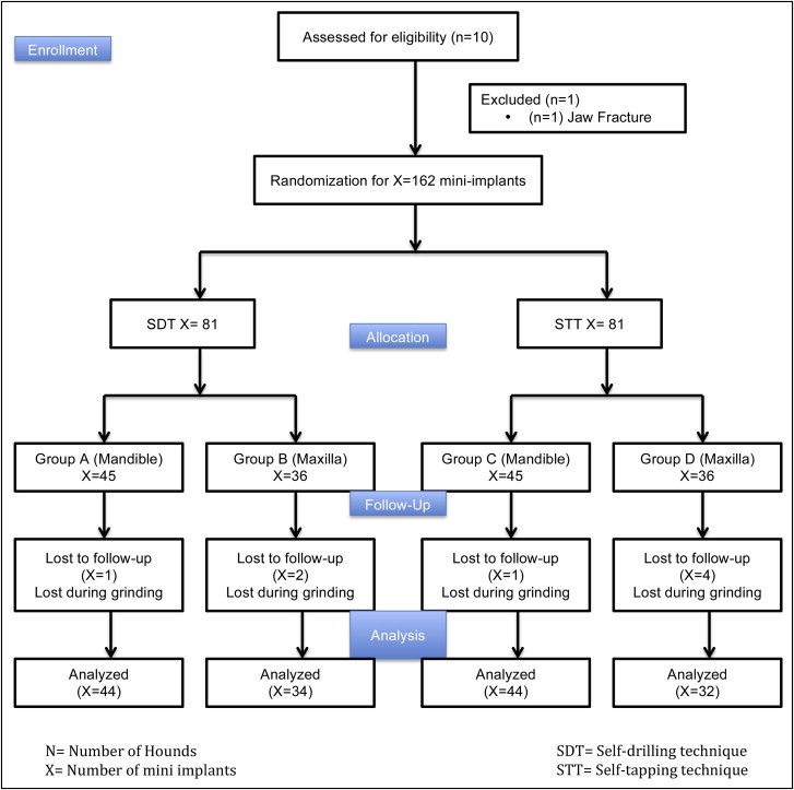
Nine adult male hounds were selected for this study. They were obtained from an unrelated study duly approved by the Institutional Animal Care and Use Committee of the University of Connecticut Health Center at Farmington, Conn. They were 12 to 14 months old with all permanent teeth present and jaw growth complete. A total of 162 mini-implants (Dentaurum, Ispringen, Germany) were placed bilaterally on the buccal sides of the mandibles and maxillae of the hounds. The mini-implants were placed immediately after the hounds were killed. The outer thread diameter of the mini-implant was 1.6 mm, and the inner core diameter of the shank was 1.3 mm (ie, the threads were 0.3 mm deep). The screw shank and threads were cylindrical for the top two thirds, and the lower third was tapered ( Fig 1 ). The total length was 6 mm. On the basis of insertion technique and the site of placement, the mini-implants were divided into 4 groups: group A, self-drilling in the mandible; group B, self-drilling in the maxilla; group C, self-tapping in the mandible; and group D, self-tapping in the maxilla. Each hound received 18 implants: 10 in the mandible and 8 in the maxilla ( Fig 2 ). The insertion techniques for the mini-implants were randomized between the maxilla and the mandible of each hound, and between the left and right sides of each jaw. The statistician (W.N.) on this project used computer-generated random numbers (Rand function, Excel 2007; Microsoft, Redmond, Wash) for allocation of the sequence. This ensured even distributions of the mini-implants placed by each technique ( Fig 3 ).
The mini-implants in groups A and B were inserted without drilling a pilot hole. In groups C and D, pilot holes were drilled with an internally irrigated twist drill 0.3 mm in length and 1 mm in diameter. The drilling rotation was 1000 rpm, and the rotational axis was clockwise. The implants were screwed into the prepared holes by using a screwdriver specifically made for this purpose. All mini-implants were inserted perpendicular to the cortical bone. One operator (Y.S.) inserted all mini-implants. The initial stability was measured with dental tweezers.
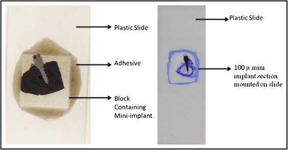
The maxillae and the mandibles of the hounds were dissected into separate bone blocks containing the specimen (mini-implant) with about 5 mm of adjacent supporting bone. Each block was assigned an identifying number by the laboratory technician on this project to which the principal investigator (Y.S.) was blinded. They were then transferred to 70% ethyl alcohol and held until processing was started. All bone blocks were stained with 1% basic fuchsin (catalog no. B660-03; J. T. Baker, Phillipsburg, NJ) as previously described and embedded in methyl methacrylate containing 0.5% initiator (Perkodox 16; AKZO, Chicago, Ill), oriented in their labeled containers and polymerized in a water bath that started at room temperature and was gradually increased over 24 hours to 34C° to polymerize the blocks. The specimens were then 2 dimensionally x-rayed with microcomputed tomography (model 1072; Skyscan, Aartselaar, Belgium) to determine each implant’s orientation in the bone block. The bone block was ground on a model trimmer to prepare a flat surface that was parallel to the plane of the mini-implant. Each specimen was then mounted on a plastic slide for further grinding with various grinding papers (K320, K500, K800, K1000, and K1200) on a grinding (milling) system (Exakt Medical Instruments, Oklahoma City, OK) until 1 side of the implant was exposed completely ( Fig 4 ). The exposed side was then polished on the grinding machine with a polishing paper and observed under the microscope to quantify any scratches. It was then mounted to a second slide by using light-cured resin (Exakt Medical Instruments). The first slide was popped off, and the block was ground on the grinding machine until the second side was exposed completely. Once the section reached the desired thickness of 50 to 70 μm, it was polished as described above and readied for microscopic analysis ( Fig 4 ). The milling on each side of the embedded implant was adjusted so that the final specimen was a central section of the implant interface with its supporting bone.
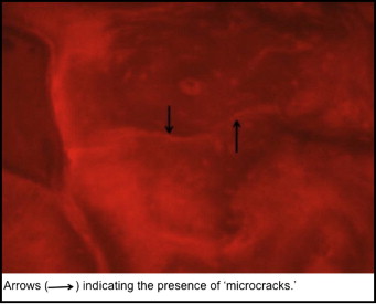
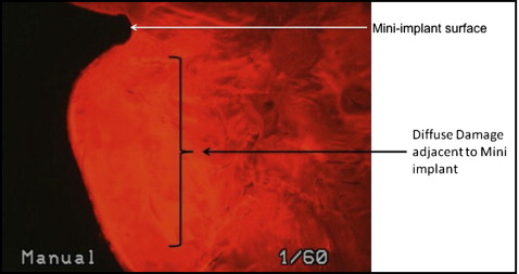
The histomorphometric parameters, microcrack length (μm) and crack surface density (μm 2 ) were evaluated (at 20 times magnification) with a microscope (model 59920; Nikon, Tokyo, Japan) and software (Osteo; Bioquant Image Analyses, Nashville, Tenn) by using the appropriate filters ( Fig 5 ). All measurements were made at 20 times magnification. Diffuse microdamage was visualized as pooled basic fuchsin that formed a diffuse staining pattern adjacent to the mini-implant ( Fig 6 ). A diffuse pattern was defined as one in which clusters of microcracks were too small to be distinguished from one another (ie, <1-2 μm).
Statistical analyses
A power analysis was conducted to determine the sample size needed to detect significant differences in crack length (measured in micrometers per 2 mm) and crack surface density (total crack length divided by 2) between the 2 insertion methods based on a paired-samples t test for data analysis. The power analysis was based on an estimated effect size (Cohen’s d) of 1.10, a conventional α level of .05, and a desired power (1 – β) of .80. Cohen’s d is an effect size estimate derived from measuring the difference between means relative to the standard deviation of the mean difference, and thus is a standardized measurement. With the specified parameters, significant differences in both dependent variables were detectable with a sample of 9 hounds. The data from this study indicated that the smallest effect size achieved was 1.13; thus, this sample size was sufficient to afford adequate statistical power to detect differences in crack length and crack density between the 2 insertion methods tested on the same subjects. All calculations were performed with the computer application G-Power (Department of Experimental Psychology, Heinrich-Heine-University, Dusseldorf, Germany), which is based on the formulas of Cohen. A cluster level analysis was used to analyze the data on crack length (μm/2 mm of area). The average of the 4 maxillary measurements for the self-drilling technique and the average of the 5 mandibular measures for the self-tapping technique were calculated, yielding a pair of averages, one for each insertion method, for each hound. The same preparation was used to produce a pair of averages for each hound for both insertion methods on the mandible. Since the measurements were clustered within dogs, a paired-samples t test was used to analyze the average differences between insertion methods at both jaw locations. A significance level of 0.05 was used for both analyses. A second cluster analysis was conducted on crack length density (total crack length divided by 2). The data were prepared in the same way as described above. Paired-samples t tests were then used to analyze the mean differences in crack density between the 2 insertion methods, both conducted by using a significance level of 0.05. An investigator (Y.S.) measured the microcrack lengths twice. The method error was calculated by using Dahlberg’s formula, Se2=Σd2/2n
S e 2 = Σ d 2 / 2 n
, where d is the difference between duplicate measurements, and n is the number of double measurements. On average, the method error for the microcrack length measurement was 0.11 mm ( P <0.05).
Stay updated, free dental videos. Join our Telegram channel
VIDEdental - Online dental courses


