Mechanical Properties of Dental Materials
Key Terms
Brittleness—Relative inability of a material to deform plastically before it fractures.
Compressive stress—Compressive force per unit area perpendicular to the direction of applied force.
Compressive strength—Compressive stress at fracture.
Ductility—Relative ability of a material to elongate plastically under a tensile stress. This property is reported quantitatively as percent elongation.
Elastic strain—Amount of deformation that is recovered instantaneously when an externally applied force or pressure is reduced or eliminated.
Elastic modulus (also modulus of elasticity and Young’s modulus)—Stiffness of a material that is calculated as the ratio of elastic stress to elastic strain.
Flexural strength (bending strength or modulus of rupture)—Force per unit area at the instant of fracture in a test specimen subjected to flexural loading.
Flexural stress (bending stress)—Force per unit area of a material that is subjected to flexural loading.
Fracture toughness—The critical stress intensity factor at the point of rapid crack propagation in a solid containing a crack of known shape and size.
Hardness—Resistance of a material to plastic deformation, which is typically produced by an indentation force.
Malleability—Ability to be hammered or compressed plastically into thin sheets without fracture.
Percent elongation—Amount of plastic strain, expressed as a percent of the original length, which tensile test specimen sustains at the point of fracture (Ductility).
Plastic strain—Irreversible deformation that remains when the externally applied force is reduced or eliminated.
Pressure—Force per unit area acting on the surface of a material (compare with Stress).
Proportional limit—Magnitude of elastic stress above which plastic deformation occurs.
Resilience—The amount of elastic energy per unit volume that is sustained on loading and released upon unloading of a test specimen.
Shear stress—Ratio of shear force to the original cross-sectional area parallel to the direction of the applied force.
Shear strength—Shear stress at the point of fracture.
Stress—Force per unit area within a structure subjected to a force or pressure (see Pressure).
Stress concentration—Area or point of significantly higher stress that occurs because of a structural discontinuity such as a crack or pore or a marked change in dimension.
Strain—Change in dimension per unit initial dimension. For tensile and compressive strain, a change in length is measured relative to the initial reference length.
Stress intensity (stress intensity factor)—Relative increase in stress at the tip of a crack of given shape and size when the crack surfaces are displaced in the opening mode (also Fracture Toughness).
Strain hardening (work hardening)—Increase in strength and hardness and decrease in ductility of a metal that results from plastic deformation.
Strain rate—Change in strain per unit time during loading of a structure.
Strength—(1) Maximum stress that a structure can withstand without sustaining a specific amount of plastic strain (yield strength); (2) stress at the point of fracture (ultimate strength).
Tensile stress—Ratio of tensile force to the original cross-sectional area perpendicular to the direction of applied force.
Tensile strength (ultimate tensile strength)—Tensile stress at the instant of fracture.
Toughness—Ability of a material to absorb elastic energy and to deform plastically before fracturing; measured as the total area under a plot of tensile stress versus strain.
True stress—Ratio of applied force to the actual (true) cross-sectional area; however, for convenience, stress is often calculated as the ratio of applied force to the initial cross-sectional area.
Yield strength—The stress at which a test specimen exhibits a specific amount of plastic strain.
Stresses and Strains
< ?xml:namespace prefix = "mml" />
 (1)
(1) (2)
(2)Tensile Stress
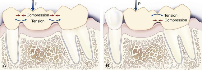
There are few pure tensile stress situations in dentistry. However, a tensile stress can be generated when structures are flexed. The deformation of a bridge and the diametral compression of a cylinder described later represent examples of these complex stress situations. In fixed prosthodontics clinics, a sticky candy (e.g., Jujube, a sticky/gummy candy) can be used to remove crowns by means of a tensile force when patients try to open their mouths after the candy has mechanically bonded to opposing teeth or crowns. However, tensile, compressive, and shear stresses can also be produced by a bending force, as shown in Figure 4-1 and as discussed in the following sections. Because most dental materials are quite brittle, they are highly susceptible to crack initiation in the presence of surface flaws when subjected to tensile stress, such as when they are subjected to flexural loading. Although some brittle materials can be strong, they fracture with little warning because little or no plastic deformation occurs to indicate high levels of stress.
Shear Stress
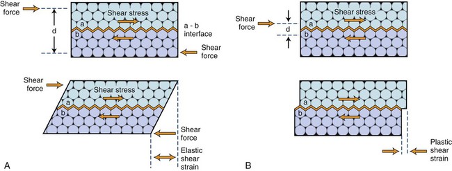
In the mouth, shear failure is unlikely to occur for at least four reasons: (1) Many of the brittle materials in restored tooth surfaces generally have rough, curved surfaces. (2) The presence of chamfers, bevels, or changes in curvature of a bonded tooth surface would also make shear failure of a bonded material highly unlikely. (3) To produce shear failure, the applied force must be located immediately adjacent to the interface, as shown in Figure 4-2, B. This is quite difficult to accomplish even under experimental conditions, where polished, flat interfaces are used. The farther away from the interface the load is applied, the more likely it is that tensile failure rather than shear failure will occur because the potential for bending stresses would increase. (4) Because the tensile strength of brittle materials is usually well below their shear strength values, tensile failure is more likely to occur.
Flexural (Bending) Stress
Examples of flexural stresses produced in a three-unit fixed dental prosthesis (FDP) and a two-unit cantilever FDP are illustrated in Figures 4-1, A, and 4-1, B, respectively. These stresses are produced by bending forces in dental appliances in one of two ways: (1) by subjecting a structure such as an FDP to three-point loading, whereby the endpoints are fixed and a force is applied between these endpoints, as in Figure 4-1, A; and (2) by subjecting a cantilevered structure that is supported at only one end to a load along any part of the unsupported section, as in Figure 4-1, B. Also, when a patient bites into an object, the anterior teeth receive forces that are at an angle to their long axes, thereby creating flexural stresses within the teeth.
As shown in Figure 4-1, A, tensile stress develops on the tissue side of the FDP, and compressive stress develops on the occlusal side. Between these two areas is the neutral axis that represents a state with no tensile stress and no compressive stress. For a cantilevered FDP such as that shown in Figure 4-1, B, the maximum tensile stress develops within the occlusal surface area since it is the surface that is becoming more convex (indicating a stretching action). If you can visualize this unit bending downward toward the tissue, the upper surface becomes more convex or stretched (tensile region) and the opposite surface becomes compressed. As explained in the section on stress concentration, these areas of tension represent potential fracture initiation sites in most materials, especially in brittle materials that have little or no plastic deformation potential.
Shown in Figure 4-2 is a bonded two-material system with the white atoms of material A shown above the interface and the shaded atoms of material B shown below the interface. The atoms are represented over six atomic planes, although dental structures have millions of atomic planes. However, the principles of stress and strain apply in both cases. In the upper section of Figure 4-2, A, a shear force is applied at distance d/2 from interface A-B. As this force increases in magnitude, it first produces an elastic shear strain (lower section of Figure 4-2), which will return to zero strain when the shear force is removed. As shown in Figure 4-2, B, if the shear force on the external surface is increased sufficiently, a permanent or plastic deformation will be produced.
For the case in Figure 4-2, B, the force is applied along interface A-B and not at a distance away, as shown in Figure 4-2, A. Because of this application of force along the interface, pure shear stress and shear strain develop only within the interfacial region. Because atoms have been displaced at near-neighbor locations, localized plastic deformation has also occurred. In the lower section of Figure 4-2, B, the force has been released and a permanent strain of one atomic space has occurred. For Figure 4-2, A, the stress induced is not pure shear since the force is applied at a distance from the interface. This is the reason why most shear bond tests do not actually measure shear strength but a tensile component of bending stress. These strength values are reported erroneously as shear strength rather than “apparent shear strength,” which indicates that pure shear was unlikely.
Elastic Properties
Elastic Modulus (Young’s Modulus or Modulus of Elasticity)
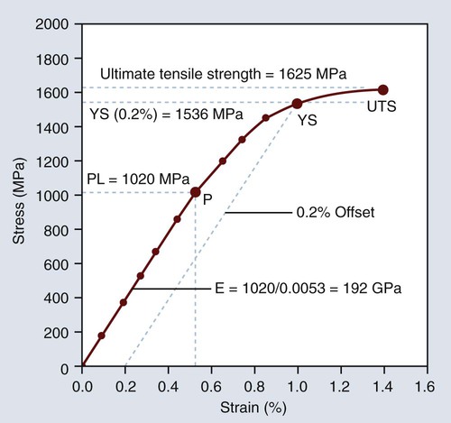
The word stiffness should come to mind upon reading one of these three terms in the dental literature. Elastic modulus describes the relative stiffness or rigidity of a material, which is measured by the slope of the elastic region of the stress-strain graph. Shown in Figure 4-3 is a stress-strain graph for a stainless steel orthodontic wire that has been subjected to a tensile force. The ultimate tensile strength, yield strength (0.2% offset), proportional limit, and elastic modulus are shown in the figure. This figure represents a plot of true stress versus strain because the force has been divided by the changing cross-sectional area as the wire was being stretched. The straight-line region represents reversible elastic deformation, because the stress remains below the proportional limit of 1020 MPa, and the curved region represents irreversible plastic deformation, which is not recovered when the wire fractures at a stress of 1625 MPa. However, the elastic strain (approximately 0.52%) is fully recovered when the force is released or after the wire fractures. We can see this easily by bending a wire in our hands a slight amount and then reducing the force. Assuming that the induced stress has not exceeded the proportional limit, it straightens back to its original shape as the force is decreased to zero.
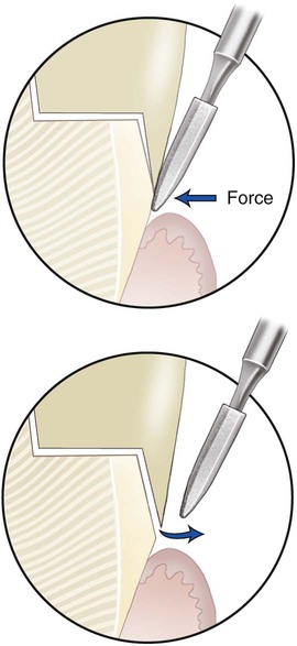
This principle of elastic recovery is illustrated in Figure 4-4 for a burnishing procedure of an open metal margin (top, left), where a dental abrasive stone is shown rotating against the metal margin (top, right) to close the marginal gap as a result of elastic plus plastic strain. However, after the force is removed, the margin springs back an amount equal to the total elastic strain. Only by removing the crown from a tooth or die can total closure be accomplished. Because we must provide at least 25 µm of clearance for the cement, total burnishing on the tooth or die is usually adequate since the amount of elastic strain recovery is relatively small.
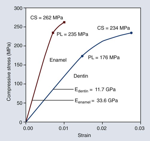
Shown in Figure 4-5 is a stress-strain graph for enamel and dentin that have been subjected to compressive stress. These curves were constructed from typical values of elastic moduli, proportional limit, and ultimate compressive strength reported in the scientific literature. If the tensile stress below the proportional limit in Figure 4-3 or the compressive stress (below the proportional limit) in Figure 4-5 is divided by its corresponding strain value, that is, tensile stress/tensile strain or compressive stress/compressive strain, a constant of proportionality will be obtained that is known as the elastic modulus, modulus of elasticity, or Young’s modulus. These terms are designated by the letter E. The units of E are usually expressed as MPa for highly flexible materials or GPa for most stiffer restorative materials. The slope of the straight-line region (elastic range) of the stress-strain graph is a measure of the relative rigidity or stiffness of a material. Although the stiffness of a dental prosthesis can increase by increasing its thickness, the elastic modulus does not change. The elastic modulus has a constant value that describes a material’s relative stiffness as determined from a stress-strain graph, which compensates for differences in cross-sectional area and length by plotting force per unit area by the relative change in dimension, usually length, relative to its initial value.
Variations in values of proportional limit, elastic modulus, and ultimate compressive strength have been reported for enamel and dentin relative to the area of the tooth from which the test specimens were obtained. Note that the proportional limit, ultimate compressive strength, and elastic modulus of enamel are greater than the corresponding values for dentin (Figure 4-5). In fact, the elastic modulus of enamel is about three times greater than that of dentin and, depending on the study considered, it can be as much as seven times higher. Dentin is capable of sustaining significant plastic deformation under compressive loading before it fractures. Thus, enamel is a stiffer and more brittle material than dentin and unsupported enamel is more susceptible to fracture. Conversely dentin is more flexible and tougher.
Because the elastic modulus of a material is a constant, it is unaffected by the amount of elastic or plastic stress induced in the material. It is independent of the ductility of a material, since it is measured in the linear region of the stress-strain plot. Thus, elastic modulus is not a measure of its plasticity or strength. Materials with a high elastic modulus can have either high or low strength values. Although a compressive test was selected to measure the properties of tooth structures in Figure 4-5, the elastic modulus can also be measured by means of a tensile test.
The elastic modulus (E) of a tensile test specimen can be calculated as follows:
Stay updated, free dental videos. Join our Telegram channel

VIDEdental - Online dental courses


