Introduction
In this study, we assessed the friction forces between various self-ligating brackets and stainless steel orthodontic wires, subjected to different shear and bending forces in the buccolingual plane.
Methods
Three kinds of self-ligating brackets and 2 kinds of ligated controls were tested in a newly developed in-vitro system. Friction was tested with stainless steel orthodontic wire in 3 deflection states. The Bonferroni multiple comparisons test was applied to evaluate intergroup differences ( P <0.05). Wire samples were examined with a scanning electron microscope before and after sliding.
Results
The results showed significant intergroup differences in friction resistance in response to wire deflection. In nonzero buccolingual deflections, passive self-ligating brackets developed higher friction forces, comparable with those in the conventional elastic ligation control group. The control brackets with reduced friction ligature had considerably lower friction forces than any other group. The active self-ligating bracket ranked between the self-ligating brackets and the reduced friction ligature group. A tribologic survey showed substantial surface alterations among wire samples coupled with passive self-ligating brackets.
Conclusions
In contrast to manufacturers’ claims, this study illustrates that, in certain clinical situations, a firm passive bracket clip can have a negative influence on the wire-bracket frictional characteristics.
The main research challenge in the study of friction in orthodontics is to estimate force levels precisely. If the friction force level is low, all the applied orthodontic force contributes to tooth movement, and its value can be approximated. When the friction force is high and difficult to assess, the wire impact on the tooth becomes obscure. As previously reported, up to 60% of the orthodontic forces applied to a tooth are used to overpower friction resistance.
Generally, friction resistance includes the following components : (1) classic friction, which depends on the force pushing the wire against a bracket slot, the coefficient of friction for specific wire-bracket combinations, the moisture environment, and the extent of the surface wear ; and (2) binding. The latter emerges as the archwire touches the corners of the bracket slot. The binding component is inevitable when orthodontic forces act on a tooth. The wire can bind against the bracket corners in any dimension, either buccolingually, incisogingivally, or both. Binding creates a significant increase in the friction resistance. However, only incisogingival binding has been extensively studied until now.
Friction force acting in the buccolingual (first order) plane is of major interest in this study. The friction force, which is proportional to the normal force, is affected by either tooth malposition, ligation auxiliaries, or both.
It is commonly believed that, among all possible ligation modes, “wire-tube” coupling has the least friction resistance to sliding. The self-ligating bracket is equipped with a metal clip, which secures the wire inside its slot and creates a tube-like structure, thus theoretically preventing or reducing the normal force component acting on the wire. The first self-ligating bracket was introduced in 1933 and became widespread by the mid-1980s. Today, there are many self-ligating bracket designs. These can be subdivided into passive and active clip designs. A passive clip does not push the wire into the slot. An active clip behaves similarly only with small wires, but larger wires are forced toward the slot floor.
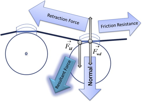
The principles that determine friction force magnitude indicate that different clip or ligature designs could affect the friction forces generated at the wire-bracket interface throughout wire deflection. In the buccolingual plane, the wire shear force, caused by tooth irregularities and, consequently, by the wire deflection, is exerted on the wire-securing auxiliary (clip, slide, ligature, elastic module, and so on). According to Newton’s third law, an equal and opposite force acts on the wire so that the system stays in static equilibrium. The magnitude of the direct and reciprocal shear forces depends on the physical properties of the wire-securing auxiliary. A stiff clip resists wire deflection and relays a higher force back onto the wire as a component of the normal force. A flexible elastic ligature, or an active clip, stretches outward and “absorbs” a certain fraction of the shear force. Consequently, less reactive force is reapplied on the wire. A balance between the initial clip force and the reciprocal clip response to the wire bending determines the normal force magnitude and the pattern of force-deflection relationsip. Figure 1 schematically represents the forces acting at the wire-slot interface, irrespective of the particular bracket system: ligature-derived force F ld —a constant force of the ligature, which is lower in self-ligating systems and higher in conventional ones—and a wire-derived force F wd —a linear function of the deflection extent and the ligature-clip resilience. Obviously, various bracket systems and the extent of tooth irregularity affect the actual values of these forces. Consequently, it was assumed that the forces exerted on the deflected wire in the buccolingual plane could be higher in self-ligating systems. This is contrary to manufacturers’ claims supported by several studies that demonstrate reduced friction in self-ligating brackets.
The objective of this study was to assess the friction force in a newly developed in-vitro system, emulating the shear force and bending moment in the buccolingual plane of tooth motion.
Material and methods
A special assembling device ( Fig 2 ), compatible with a materials testing machine (Twin Column LR10K with 10-kN load cell, Lloyd Instruments, Bogner Regis, West Sussex, UK, United Kingdom), was constructed: it consisted of a rectangular aluminum plate (vertically oriented) and 3 horizontal rods (hardened steel) arranged on the upper part of the device. The flanking rods were fixed, and the middle rod was mobile. The mobile rod was secured to the base plate with a spring and equipped with two removable microscrews from behind. The assembling device was precisely centered under the load cell grip along the vertical axis of the testing machine.
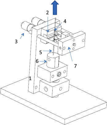
In each experimental setup, 3 brackets were aligned on the rods of the assembling device with a full-size guiding wire (stainless steel, 0.016 × 0.022 in, with the larger dimension facing the brackets’ slot floor) and a positioning fork. The guiding wire passed from the weight orifice through 3 brackets and was intended to level the slots relative to each other in the third-order plane. The positioning fork was used to set the interbracket distances (4.7 mm), to push the brackets equally against the rods and to ensure a similar adhesive layer at the bracket base of all tested brackets.
The wire section ran vertically, centered exactly above the bracket slot. The upper end of the wire was connected to the load cell with a custom-made screw grip. The lower end of the wire carried a 1.5-N brass weight (screw grip), which was intended to maintain a constant preload in the system. A cylindrical weight passed through a guiding orifice of slightly larger diameter to constrain its pendulum oscillations.
Of the 5 bracket brands tested, there were 3 self-ligating brackets: 2 passive (Damon2, Ormco, Glendora, CA, USA) SmartClip, 3M Unitek, Monrovia, CA, USA) and 1 active (In-Ovation, GAC International, Bohemia, NY, USA). Two types of ligated bracket controls were used: a conventional bracket Victory-MBT prescription (3M Unitek) with “Slide” low friction ligatures (Leone America, Avondale, AZ, USA) and Victory-MBT prescription bracket with conventional elastomeric ligatures (elastic o-modules, Sani-Ties Silver, GAC International). All brackets were upper central incisor brackets, 0.022 × 0.028 slot, torque of 12° (Damon2, In-Ovation) or 17° (SmartClip, Victory). The main consideration for choosing the upper incisor bracket with nonzero built-in torque was the geometry of its base, since a flat bracket base allows good surface contact and a thinner adhesive layer to meet bonding shear strength requirements. These requirements were of primary importance in this study, because the shear force values of the full-sized stainless steel wires were expected to be high and could have caused bond failure. The positioning fork also ensured equal torque in the base at the mounting stage. Therefore, a certain torsion of the wire was foreseen, identical for each bracket in a 3-bracket array and in all arrays. A rigid working archwire was chosen for the study: stainless steel, 0.019 × 0.025 in (3M Unitek), received in straight sections of 360 mm. This wire was the same in all bracket systems used in this study.
The testing machine was checked and calibrated, and the experimental protocol was established. A preliminary experiment was performed to assess the magnitude of normal beam loading via 3-points bending without the wire dragging along the brackets. The specific purpose of the test was to determine the range of clinically reasonable wire deflections. The preliminary 3-points bending test was performed with each bracket system and 0.019 × 0.025-in stainless steel wire. The wire was placed into the slots of 2 brackets, positioned in line. A custom hook, connected to the load cell, held the wire in the middle of the double interbracket span (9.4 mm) and elevated the wire to 1.0 mm, and then the wire was released. The strain values on loading and unloading were obtained, and load-deflection curves were constructed to estimate the range of strain per 0.1-mm deflection for all groups ( Table I ).
| Bracket | Damon | In-Ovation | SmartClip | Victory-Slide | Victory-module |
|---|---|---|---|---|---|
| Load at 1.0-mm deflection (N) | 8.67 | 6.6 | 9.43 | 6.75 | 8.73 |
| SD (N) | 1.29 | 1.13 | 1.51 | 1.3 | 2.02 |
For the friction test with buccolingual wire deflection, 3 brackets of each group were mounted on hardened steel rods of the testing device with HighQ Bond SE (self-etching, dual-cured permanent adhesive resin cement, BJM Laboratories, Or-Yehuda, Israel). The interbracket distance was set at 4.7 mm, representing a typical distance in the canine-premolar region. By using microscrews, the central rod projection could be set at the desired middle bracket projection value. The projection values of the middle bracket were 0.0, 0.15, and 0.2 mm. As the reference point, the 0.0-mm value was chosen. The second value represented a critical deflection magnitude, where the binding effect is expressed at first. According to the equation of concentrated beam load (“Discussion”), the threshold binding value of the wire deflection was calculated. If the load is not supposed to exceed 3 N, the maximum deflection value should be 0.0561 mm. Considering the wire-slot play in the buccolingual plane of 0.076 mm, the maximum middle bracket deviation was 0.1321 mm. For simplification and clarity, the 0.15-mm bracket set-out value was chosen.
The next measurement point was set at 0.2 mm, which corresponds to a load of approximately 7 N. This value is high from the clinical point of view, yet still appropriate for laboratory measurement.
The assembling device was attached to the base of the testing machine. A 70-mm stainless steel wire segment was connected to the load cell and to the counterweight mass; the wire was then engaged into the bracket slots according to the manufacturers’ recommendations. Self-ligating brackets were tested in closed position. The wire was drawn up through the brackets with a constant speed of 5 mm per minute for 1 minute. Ten sequential readings were taken, and then a new testing model was mounted. Each possible bracket-deflection combination was examined 5 times. Fifty readings were obtained in each of the 5 groups with 3 wire deflection states (0.0, 0.15, and 0.2 mm). In all arrays, static and kinetic friction force values were recorded, and graphic images were captured with NEXYGEN MT Materials Test and Data Analysis Software (Chatillon Force Measurement Systems, Largo, FL, USA). All measurements were made by the first author (N.R.). Random test sequences were developed to minimize learning-curve influences on the precision of the results.
All wire samples were collected and labeled, soaked in alcohol, dried in air, and viewed under 10 times magnification. The location of friction impact was located when possible; 10-mm sections were cut from the sample and inspected with a scanning electron microscope (SEM) (FEI Quanta200, Eindhoven, The Netherlands) at 200 and 1000 times magnification.
The null hypothesis (H 0 ) implied that there was no difference, beyond random variation, among self-ligating brackets of different designs and conventional brackets. The alternative hypothesis (H 1 ) was that there was an effect of bracket design on the wire shear and bending forces in the buccolingual plane. (H 0 : mean (B) – mean (A) = 0; H 1 : mean (B) – mean (A) ≠ 0).
The means and standard deviations of the friction force resistance were calculated. The diversity of the results between the various bracket and deflection combinations was analyzed with the Bonferroni multiple-comparison tests model. Statistical significance was determined at the P <0.05 level. The statistical analysis was performed by Gan Statistics, Biostatistics & Consultation, Timrat, Israel.
Results
For rigid wires, the stress-strain ratio is linear. In agreement with the preliminary experiment, for each 0.1 mm of wire deflection, the bending force (ie, normal, in respect to the bracket) increased between 0.6 and 1.0 N ( Table I ).
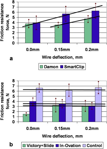
During the friction test, curves of “resistance force vs displacement” were obtained. The mean static friction force and its standard deviation for each group in different deflections are summarized in Table II . The values were compared among the groups, separately for each deflection state.
| Deflection (mm) | Bracket | Damon (n = 50) | In-Ovation (n = 50) | SmartClip (n = 50) | Victory-Slide (n = 50) | Victory-module (n = 50) |
|---|---|---|---|---|---|---|
| Friction resistance force (N) | ||||||
| 0 | Mean | 3.757 | 3.966 | 3.909 | 1.478 ∗ | 6.626 † |
| SD | 1.406 | 1.554 | 2.589 | 0.637 | 1.845 | |
| 0.15 | Mean | 3.537 | 3.490 | 5.692 † | 3.237 | 6.115 † |
| SD | 1.112 | 1.696 | 2.758 | 2.848 | 2.349 | |
| 0.2 | Mean | 4.703 | 3.158 ∗ | 6.256 † | 3.008 ∗ | 6.701 † |
| SD | 1.189 | 1.349 | 2.890 | 2.168 | 2.283 |
∗ Significantly lower value among different bracket groups
† significantly higher value among different bracket groups; Bonferroni multiple-comparison tests model, P <0.05 level; n , number of readings.
Five examined bracket groups were divided into 2 subgroups according to the deflection-load regression pattern. A linear relationship between deflection and load served as a marker for the bracket subgroup sorting. The shear force component was predominant in the subgroup with a linear relationship between deflection and load. Friction resistance value independent on deflection indicated that the wire locking mechanism was mainly responsible for the friction force ( Fig 3 ). The subgroups were the following: Damon and SmartClip, associated with linear increase of the friction resistance force with respect to the wire deflection value; and In-Ovation and both Victory groups, associated with constant friction-resistance force, not depending on the wire deflection magnitude. Since the second deflection value of 0.15 mm was referred to as a threshold value (where the initial binding occurs) and the third point presumably reflects extensive binding, the key feature for the groups’ subdivision—constant vs linear pattern—was the relationship of the friction forces at the second and third points (rather than the first and second points).