Introduction
Mandibular canines are anatomically extruded in approximately half of the patients with a deepbite. Although simultaneous orthodontic intrusion of the 6 mandibular anterior teeth is not recommended, a few studies have evaluated individual canine intrusion. Our objectives were to use the finite element method to simulate the segmented intrusion of mandibular canines with a cantilever and to evaluate the effects of different compensatory buccolingual activations.
Methods
A finite element study of the right quadrant of the mandibular dental arch together with periodontal structures was modeled using SolidWorks software (Dassault Systèmes Americas, Waltham, Mass). After all bony, dental, and periodontal ligament structures from the second molar to the canine were graphically represented, brackets and molar tubes were modeled. Subsequently, a 0.021 × 0.025-in base wire was modeled with stainless steel properties and inserted into the brackets and tubes of the 4 posterior teeth to simulate an anchorage unit. Finally, a 0.017 × 0.025-in cantilever was modeled with titanium-molybdenum alloy properties and inserted into the first molar auxiliary tube. Discretization and boundary conditions of all anatomic structures tested were determined with HyperMesh software (Altair Engineering, Milwaukee, Wis), and compensatory toe-ins of 0°, 4°, 6°, and 8° were simulated with Abaqus software (Dassault Systèmes Americas).
Results
The 6° toe-in produced pure intrusion of the canine. The highest amounts of periodontal ligament stress in the anchor segment were observed around the first molar roots. This tooth showed a slight tendency for extrusion and distal crown tipping. Moreover, the different compensatory toe-ins tested did not significantly affect the other posterior teeth.
Conclusions
The segmented mechanics simulated in this study may achieve pure mandibular canine intrusion when an adequate amount of compensatory toe-in (6°) is incorporated into the cantilever to prevent buccal and lingual crown tipping. The effects on the posterior anchorage segment were small and initially concentrated on the first molar.
Highlights
- •
Our results may help orthodontists improve efficiency during leveling of the curve of Spee.
- •
We tested different segmented arch mechanics to achieve pure mandibular canine intrusion.
- •
Compensatory toe-ins are needed to achieve pure mandibular canine intrusion.
Many orthodontic patients have a deepbite, and this vertical discrepancy is often corrected with intrusion of the mandibular anterior teeth. Approximately 50% of patients with deepbite have anatomically extruded mandibular canines. Because simultaneous orthodontic intrusion of the 6 anterior teeth can cause undesirable effects in the posterior anchorage segment, segmented intrusion of the mandibular canines should be considered when leveling the curve of Spee.
Surprisingly, only a few reports have described methods for individual intrusion of the canines. One technique was described by Ricketts et al and involved using the utility arch after complete incisor intrusion as a stabilization arch and gently tying an elastic band from the canine bracket to a step-down bypass segment in the utility arch. Another technique was reported by Marcotte, who suggested the use of a cantilever from the auxiliary tube of the first molar to the canine bracket slot. However, these techniques do not include a method for controlling the buccolingual inclination; apparently, no research has proven whether and how these mechanics truly intrude the canines.
Burstone also described a technique for individual intrusion of the canines that included a slight compensatory toe-in bend to deliver a lingual force for controlling the tendency of buccal crown tipping of the canine. Despite the improved control of the buccolingual inclination, the cantilever had to be inserted into a vertical slot of the canine bracket, requiring the addition of 3 helices to the cantilever and tiebacks to both the buccal and lingual aspects of the canine. Therefore, this technique was often considered uncomfortable for patients and clinically complex for orthodontists. Because uncontrolled canine intrusion may lead to buccal crown tipping and thus to increased mandibular intercanine width, it could also increase the chances of orthodontic treatment relapse. Therefore, there is still a need to improve the clinical approach for intruding the mandibular canines while adequately leveling the curve of Spee.
The finite element method (FEM) is commonly used in engineering studies, but it has more often been used in orthodontics to better understand the effects of different mechanics. The method consists of a graphic computer simulation of different objects that are divided by a process known as “discretization” into small segments called “elements.” The “elements” are numbered in a finite number of points called “nodes” that are defined by their global coordinates. The FEM enables the evaluation of biomechanical effects such as stress and strain on human body parts that are difficult to access without causing harm to subjects.
The purposes of this study were to use the FEM to simulate the segmented intrusion of a mandibular canine with a cantilever and to evaluate the effects of different compensatory buccolingual activations on both the canine and the posterior teeth, which served as anchorage units.
Material and methods
The construction of the FEM model was performed using SolidWorks software (Dassault Systèmes Americas, Waltham, Mass). A mandibular segment from the right second permanent molar to the right permanent canine was obtained from a previous study of our research group and was updated and improved. All teeth were modified until the proper crown-to-root ratio was obtained. The teeth from this segment were aligned according to the peer assessment rating index. The posterior teeth from the second molar to the first premolar were leveled, and the canine with its surrounding alveolar bone was extruded by 1.5 mm. A periodontal ligament (PDL) was modeled with 0.20-mm linear thickness, as previously described in other FEM studies.
After all bony, dental, and PDL structures were graphically represented, brackets and molar tubes were modeled with 0.022 × 0.028-in slots and 0° of tip and torque. The first molar auxiliary tube had an 0.018 × 0.025-in slot, as is common for most double tubes available on the market. A 0.021 × 0.025-in base wire was also modeled to passively fill the second molar tube, the first molar main tube, and the premolar bracket slots to simulate the posterior anchorage segment. This passive fit of the base wire into the posterior appliances was achieved because of the preleveling and alignment. All brackets and tubes, and the base wire were assumed to be composed of stainless steel. The properties of all materials simulated in this study were based on previous reports from the literature ( Table I ).
| Elastic modulus | Poisson’s ratio | |
|---|---|---|
| Tooth | 20 GPa | 0.3 |
| Periodontal ligament | 0.71 MPa | 0.4 |
| Bone | 345 MPa | 0.3 |
| Stainless steel | 200 GPa | 0.3 |
| Titanium-molybdenum alloy | 69 GPa | 0.3 |
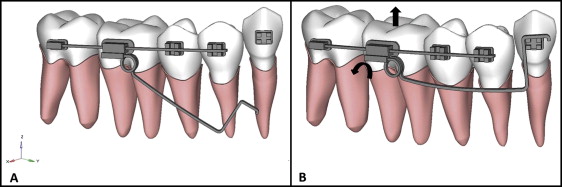
The cantilever simulated in this study had a cross-section of 0.017 × 0.025 in and the properties of titanium-molybdenum alloy. The distal end of the cantilever was fitted inside the first molar auxiliary tube, and a helix 3 mm in diameter was constructed mesially to be flush to the tube. There was a horizontal segment extending mesially to the area corresponding to the interproximal contact point between the first premolar and the canine. At this point, a 90° bend was modeled occlusally, comprising a vertical segment that ended at the level of the uppermost portion of the canine bracket. Finally, another 90° bend was made to generate the final segment of the cantilever, which was in contact with the upper part of the canine bracket. The FEM constructed for this experiment and used for all simulations is shown in Figure 1 .
After the model construction, discretization and boundary conditions of the anatomic structures tested were performed using HyperMesh software (Altair Engineering, Milwaukee, Wis). The PDL and the alveolar bone had hybrid meshes with pentahedron and hexahedron elements, which provided more accurate estimations of the stresses on these structures. The sophistication of the mesh was important because the PDL was being evaluated for stress in this study. The other objects had pentahedron elements, and each element had 6 degrees of freedom; thus, they could move and rotate in any direction within the space. Finally, each pentahedron element had 6 nodes, and each hexahedron element had 8 nodes.
The interactions between the brackets and wires were determined using beam elements. The remaining interactions between the elements of different objects were made by rigid contact interactions, in which phases from the different materials remain without relative displacement between them.
Three reference axes with the mandibular canine as the reference point were used for cantilever activation: (1) x-axis for the buccolingual aspect, (2) y-axis for the mesiodistal aspect, and (3) z-axis for the occlusogingival direction. All cantilevers tested were activated with a 35° tip-back ( Fig 1 ), which produced forces of 0.02 N on the y-axis and 0.37 N on the z-axis. This was achieved by prescribing a displacement vector at the bottom of the cantilever, which was in contact with the canine bracket. After achieving this position, the cantilever was caught by a rigid link. Thus, all of the energy accumulated at the offset was transmitted to the bracket and then to the tooth. The following compensatory toe-ins were simulated in this experiment: 0°, 4°, 6°, and 8°.
The activation of each simulated compensatory toe-in was equivalent to the magnitude of the force in the x-axis inferred from the visualization correspondent to the force that each toe-in produced ( Table II ). Therefore, the force variation was only in the x-axis. All simulations were performed using Abaqus software (Dassault Systèmes Americas).
| Toe-in (°) | Force in the x-axis (N) |
|---|---|
| 0 | 0.01 |
| 4 | 0.052 |
| 6 | 0.082 |
| 8 | 0.12 |
Results
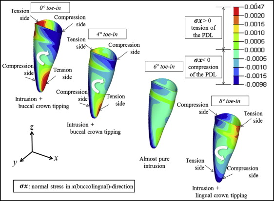
There was a tendency for buccal crown tipping of the mandibular canine when a passive (0°) toe-in was simulated. The intensity of this buccal tipping tendency decreased as the amount of compensatory toe-in increased. When a compensatory toe-in of 6° was simulated, the buccal crown tipping tendency was completely eliminated. Conversely, when a toe-in of 8° was simulated, the tendency of movement changed to lingual crown tipping. Figure 2 shows the stress in the PDL. Figure 3 illustrates the tooth displacement patterns calculated by the FEM as a consequence of the cantilever activation, with all degrees of toe-ins tested.